Rep:Y3.C3 og108
Year 3 Computational Lab Module 3: Transition State Structures Oliver Garnett See also Y3.C2_og108
Previous modules have explored the structures of stable organic and inorganic molecules, now analysis of transition state structures will be studied. The reactions chosen for this investigation are the Cope rearrangement and Diels Alder cycloaddition reactions.
A transition state can be defined as the geometry a molecule assumes at the saddle point on a potential energy surface. Transition state theory is focused on accounting for the kinetics of a reaction using the potential energy surface. The energy of the transition state relative to the reactants is known at the activation energy. This energy barrier dictates which product is formed fastest in a reaction and explains why some products are favoured over others despite sometimes not being the most thermodynamically stable.
The Cope Rearrangement
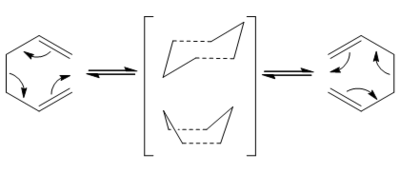
The first reaction under study for transition state analysis is the Cope rearrangement. This reaction was developed by Arthur C. Cope and is a [3,3] sigmatropic rearrangement of 1,5-dienes. The reaction can be viewed as a concerted pericyclic reaction, for the purposes of this investigation, transition state theory will be employed to understand the reaction dynamics. The rearrangement will be observed via both the boat and chair transition states.
 |
Establishing Reactants and Products
First, a starting point for studying the transition states must be established by focusing on the reactant and product molecules (which are structurally identical). The optimised geometry and energy of different conformational isomers of 1,5-Hexadiene are studied to find which are the most stable.
Optimisation and Confirmational Analysis
A conformational isomer usually occurs as a result of the low kinetic barrier for rotation about a σ-bond. If the energy of the system is plotted as a function of the rotation about the σ-bond then one ore more mimia will arise along the curve. These minima have a finite lifetime and therefore have an associated zero-point energy, entropy and free energy[1].
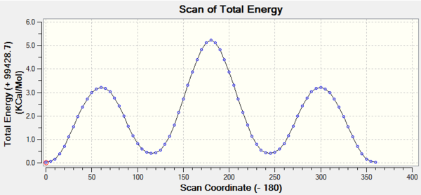
The variance of energy with angle of rotation about a C-C σ-bond can be attributed to three effects:
- The orbital overlap (bond orientation) effect arises from alignment of σ and σ* orbitals leading to NBOs. This favors the antiperiplanar conformation and is the most significant of the three effects.
- Pauli repulsions which disfavor any eclipsed orientations.
- Dispersion (Van der Waals) forces which are isotropic and operate at longer range than the other two effects. This effect is highly dependent on the functional groups on either side of the C-C bond.
Taking these three effects into account one can deduce that the most stable conformation about a RH2C-CH2R σ-bond should be an antiperiplanar form[3].
The energies of the main conformations of 1,5-Hexadiene were established first to establish a starting point structure.
| Conformer | Point Group | Total Energy (Hartrees) | Relative Energy*(Kcal mol-1) |
|---|---|---|---|
| Gauche 1 [4] | C2 | -231.68772 | +3.100 |
| Gauche 2 [5] | C2 | -231.69167 | +0.621 |
| Gauche 3 [6] | C1 | -231.69266 | 0.000 |
| Gauche 4 [7] | C2 | -231.69153 | +0.709 |
| Gauche 5 [8] | C1 | -231.68962 | +1.908 |
| Gauche 6 [9] | C1 | -231.68916 | +2.196 |
| Anti 1 [10] | C2 | -231.69260 | +0.038 |
| Anti 2 [11] | Ci | -231.69254 | +0.075 |
| Anti 3 [12] | C2h | -231.68907 | +2.253 |
| Anti 4 [13] | C1 | -231.69097 | +1.060 |
- Energy relative to most stable conformer (gauche 3 in this case). 1 Hartree = 627.503 kcal mol-1[14]
Anti 1, anti 2, and Gauche 3 appear to be at least an order of magnitude more stable than the other conformations. However the most stable of these is Gauche 3 which is surprising since from chemical intuition one would expect the most stable conformer to be an antiperiplanar form as discussed previously.
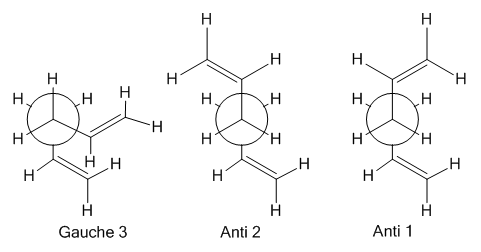
This is possibly a result of unexpectedly strong Van der Waals forces stabilising the closer proximity of the two alkenes. The closest alkene hydrogen's in the gauche 3 form were measured to be 2.62A apart which is a little too far to be significantly attractive. Alternatively the calculation being performed at the HF/3-21G may be too inaccurate to distinguish accurately the energy of these conformations. Therefore, these conformers were re-optimised using the more rigorous density functional theory approach at the DFT/B3LYP/6-31G(d) level. This provided a more accurate view of the relative energies.
| Conformer | Point Group | Total Energy (Hartrees) | Relative Energy (Kcal mol-1) |
|---|---|---|---|
| Anti 1 [15] | C2 | -234.61179 | +0.000 |
| Anti 2 [16] | Ci | -234.61171 | +0.050 |
| Gauche 3 [17] | C1 | -234.61133 | +0.289 |
The Anti 1 and Anti 2 conformers now appear to be more stable than the Gauche 3 conformer by around 0.2Kcal mol-1. This is in line with previous predictions and is likely caused by the larger basis set 6-31G* which can account for the strongly stabilising stereoelectronic effects (effect 1 discussed previously). The Antiperiplanar conformations can be stabilised in this way from σ(C-C) → σ*(C-C) donation which is slightly more stable than σ(C-H) → σ*(C-C) donation seen in gauche forms because of the better orbital overlap. There are also noticable differences in some of the dihedral angles after the re-optimisation.
Frequency Analysis
Frequency analysis on the DFT optimised structures verified that the low energy conformations correspond to local minima.The analysis provides 42 distinct positive vibrational modes which are very similar for all 3 conformers.
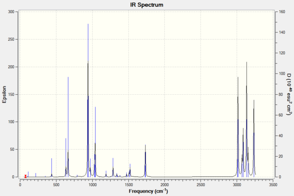
Only positive vibrational modes were seen indicating the optimised structures are those of local minima. The alkene stretching modes can distinguish the conformers and have been tabulated below.
| Conformer | Symmetrical C=C Stretching mode / cm-1 | Asymmetrical C=C Stretching mode / cm-1 |
|---|---|---|
| Anti 1 [18] | 1732 [4.73]Show Animation | 1735 [13.55]Show Animation |
| Anti 2 [19] | 1731 [0.00]Show Animation | 1734 [18.13]Show Animation |
| Gauche 3 [20] | 1732 [6.88]Show Animation | 1733 [6.13]Show Animation |
Although these values are all fairly similar, the differences do highlight the importance of symmetry in determining the number of peaks displayed in an IR spectrum. Experimental literature values are around 1620 - 1680cm-1[21] which are not similar to the values shown above. It should however be noted that literature values do not distinguish between different conformations as the rotations are faster than the timescale for IR spectroscopy.
Thermochemical Analysis
A deeper look into the log files from the frequency analysis allows thermochemical data to be uncovered.
Anti 2 Conformer at 298K
 Zero-point correction=                           0.142507 (Hartree/Particle)
 Thermal correction to Energy=                    0.149853
 Thermal correction to Enthalpy=                  0.150797
 Thermal correction to Gibbs Free Energy=         0.110933
 Sum of electronic and zero-point Energies=           -234.469204
 Sum of electronic and thermal Energies=              -234.461857
 Sum of electronic and thermal Enthalpies=            -234.460913
 Sum of electronic and thermal Free Energies=         -234.500777
Modifying the input file allows the analysis to be performed at different temperatures and pressures. This was then compared to the calculation at room temperature.
Anti 2 Conformer at 0K [22]
 Zero-point correction=                           0.142507 (Hartree/Particle)
 Thermal correction to Energy=                    0.142507
 Thermal correction to Enthalpy=                  0.142507
 Thermal correction to Gibbs Free Energy=         0.142507
 Sum of electronic and zero-point Energies=           -234.469204
 Sum of electronic and thermal Energies=              -234.469204
 Sum of electronic and thermal Enthalpies=            -234.469204
 Sum of electronic and thermal Free Energies=         -234.469203
The data shows all energy sums are the same for the calculation at 0K since at this temperature no energy contributions come from thermal activity. These are in turn the same as the sum of the electronic and zero-point energies for the calculation at room temperature which is also expected since the zero point energy is the energy of the ground state of a quantum mechanical system.
From comparison of the data at 0K and room temperature it can be seen that increasing the temperature raises the thermal energy and thermal enthalpy terms, while the free energy term decreases. Clearly raising the temperature will increase the thermal contributions to the energy and enthalpy terms in lines two and three of the data. The behavior of the free energy term can be rationalised using the the Gibbs Free Energy equation: G(p,T) = H − TS. From this it can be seen that an increase in temperature results in a lower free energy.
Transition States
Now that the structures of the more stable reactants has been established, the transition state structures may be found.
Optimisation
Transition states are more difficult to optimise since a maxima rather than a minima stationary point is being located. A range of different techniques will be employed to optimise these structures and these will be compared.
Firtsly an allyl fragment was constructed and optimised which would be used to form the transition state structures and for further calculations. This calculation was performed at the HF/3-21g level and the optimised C2v structure can be seen here .
Chair-like Structure
Optimisation 1[23]: A "guess" transition structure was used as a starting point for a optimisation to a minimum TS (Berny). This was done by pasting two of the previously optimised allyl fragments and oreintating them into a chair structure on Gaussview 5.0 with the terminal alkenes being set 2.2Å apart as shown in figure 6.
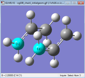
This guess structure was then subject to an optimisation and frequency analysis using a Hessain force constant matrix. The force constant was calculated once and the parameter "Opt=NoEigen" was also added to stop the calculation crashing if more than one imaginary frequency is detected which commonly occurs if the guess structure is not close enough to the actual transition state.
Filename = //icfs16.cc.ic.ac.uk/og108/Desktop/Labs/3rd Year Labs/
Computational/Module 3/Part 1/Chair/output/og108_chair1_optTSB3.out

chair1 optTSB1
File Name = og108_chair1_optTSB3
File Type = .log
Calculation Type = FTS
Calculation Method = RHF
Basis Set = 3-21G
Charge = 0
Spin = Singlet
E(RHF) = -231.61932246 a.u.
RMS Gradient Norm = 0.00000977 a.u.
Imaginary Freq =
Dipole Moment = 0.0005 Debye
Point Group = C1
Job cpu time:  0 days  0 hours  2 minutes 20.3 seconds.
The above shows the molecular energy is -231.61932 Hartrees, similar to that given in Appendix 2. The terminal bond lengths of the optimised structure had been reduced to 2.02Å.
Frequency analysis from this calculation shows an imaginary vibrational mode at -817.96 cm-1 representitive of the chair transition state. The negative nature of the vibrational mode arises from the second derivative of the potential energy surface implies a energy maximum has been reached.
Optimisation 2[24]: Once again the guess structure was used as a starting point in preperation for the frozen coordinate optimisation method. The terminal bonds were "frozen" at a length of 2.2Å and the rest of the molecule was optimised. A second optimisation was then performed to minimise the terminal bond lengths to a transition state (Berny) but without calculating the force constants as with the first method. The resulting structure can be viewed here: .
Filename = //icfs16.cc.ic.ac.uk/og108/Desktop/Labs/3rd Year Labs
/Computational/Module 3/Part 1/Chair/output/og108_chair1_optderivative2.out

chair opt derivative
File Name = og108_chair1_optderivative2
File Type = .log
Calculation Type = FTS
Calculation Method = RHF
Basis Set = 3-21G
Charge = 0
Spin = Singlet
E(RHF) = -231.61932203 a.u.
RMS Gradient Norm = 0.00004051 a.u.
Imaginary Freq =
Dipole Moment = 0.0004 Debye
Point Group = C1
Job cpu time:  0 days  0 hours  0 minutes 55.8 seconds.
It appears that the energy for the first method was actually fractionally lower than that for the frozen coordinate method. The RMS Gradient is also closer to 0 and so the transition structure is at a flatter point on the potential energy curve. This implies that the first method was more effective for finding the optimised transition state structure. This would therefore suggest that the guess structure used was already very close to the optimised transition state. If a more complicated molecule had been used with a transition state that is more difficult to predict, then the the first method may not be the most effective or even reached a transition state at all.
Boat-like Structure
A new method was used for the boat optimisation which involves interpolating between the reactant and product structures to find the transition state. This method unfortunately requires careful numbering of each atom to ensure the products correlate to the reactants. The first attempt failed to produce the correct structure:
The geometry of reactant and product structures were adjusted, changing the C2-C3-C4-C5 dihedral angle to 0° and the two inside C-C-C angles to 100°. The new geometry allowed a fully optimised boat transition structure to be obtained:
Filename = //icfs16.cc.ic.ac.uk/og108/Desktop/Labs/3rd Year Labs/Computational
/Module 3/Part 1/Boat/output/og108_boat1_optQST2_2_7.out

boat optQST2 2 7
File Name = og108_boat1_optQST2_2_7
File Type = .log
Calculation Type = FREQ
Calculation Method = RHF
Basis Set = 3-21G
Charge = 0
Spin = Singlet
E(RHF) = -231.60280108 a.u.
RMS Gradient Norm = 0.00017457 a.u.
Imaginary Freq = 1
Dipole Moment = 0.1591 Debye
Point Group = C2V
Job cpu time:  0 days  0 hours  0 minutes 12.5 seconds.
Frequency analysis uncovered a single imaginary vibrational mode at -840.98 cm-1 corresponding to a boat transition state structure and is slightly different to the chair vibrational mode though different optimisation methods were used. The vibration shows how terminal σ bonds form and break during the vibration which is typical for an imaginary vibration of transition state structure.
Intrinsic Reaction Coordinate (IRC)
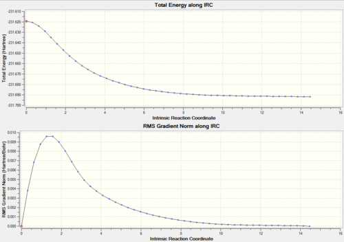
This process allows the minimum energy path to be followed from the transition state to its local minima on the PES, in this case the product. This shows which conformations the transition state is connected to and would be impossible to achieve simply through inspection of the structures. All calculations were carried out at the HF/3-21G level in the forward direction only since the reaction is reversible and symmetrical. The chair transition structure was used to find the most efficient IRC method and this method was then used for the Boat structure as well.
Initial IRC: The first calculation was performed with 50 points along the IRC.
This calculation failed to reach a minumum geometry so three different methods were tested to achieve this:
IRC 1: This calculation was simply an optimisation of the final structure from the previous IRC calculation to reach a local minima.
IRC 2: Another calculation was then performed but with 150 points along the IRC as opposed to only 50.
IRC 3: Finally the a last calculation was performed in which all the force constants were computed. This is usually by far the most effective method but is computationally expensive and generally is quite impractical for larger systems.
A summary of the 4 methods used is shown below. Once the most effective method was established then this was performed on the boat transition structure as well.
| IRC Method | Transition state | Maximum points along the IRC | Terminated After (Steps) | Compute Force Constant | RMS Gradient | Total Energy |
|---|---|---|---|---|---|---|
| 1 | Chair[27] | 50 | 26 | Once | 0.00000281 | -231.69166702 |
| 2 | Chair[28] | 150 | 26 | Once | 0.00000975 | -231.61932246 |
| 3 | Chair[29] | 50 | 47 | Always | 0.00000975 | -231.61932246 |
| 3 | Boat[30] | 50 | 51 | Always | 0.00001086 | -231.60280247 |
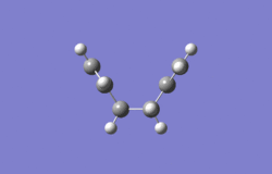
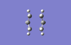
The two movies below show the structural changes that occur as the potential energy surface is followed from the transition state down to a local minima:
 |
 |
 |
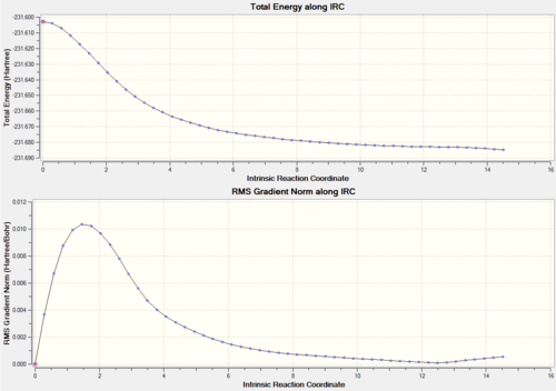 |
The final energy point on the chair IRC was at -231.692 and for the Boat -231.685 Hartrees. This is close enough to a local minimum for the IRC to be considered a success and from this it was determined that the boat transition state tends to the gauche 1 conformation whereas the Chair tends to gauche 2 conformer.
Energy and the Activation Energy
A table of energies for both transition structures was generated to determine which was the more stable. A comparison can also be made for both levels of theory by analysing the activation energies generated from each method. Therefore the reactant molecule was included for these calculations.
| Structure | HF/3-21G | B3LYP/6-31 | ||||
|---|---|---|---|---|---|---|
| Electronic Energy | Sum of Electronic & Thermal Energies (298.15K) | Sum of Electronic & Zero-point Energies (0K) | Electronic Energy | Sum of Electronic & Thermal Energies (298.15K) | Sum of Electronic & Zero-point Energies (0K) | |
| Chair | -231.619322 [31] | -231.461339 | -231.466698 [32] | -234.556982 [33] | -234.408983 | -234.414905 [34] |
| Boat | -231.450929 [35] | -231.445300 | -231.450929 [36] | -234.543093 [37] | -234.396005 | -234.402338 [38] |
| Anti 2 Conformer (reactant) | -231.692535 [39] | -231.532566 | -231.539540 | -234.611710 [40] | -234.460913 | -234.469204 [41] |
Using the data above the activation energy can be calculated at 298.15K and at 0K by subtracting the sum of the electronic and thermal energies of the reactants from that of the transition state.
| Structure | HF/3-21G | B3LYP/6-31 | Experimental Literature Value at 0K [42] | ||
|---|---|---|---|---|---|
| At 298.15K | At 0K | At 298.15K | At 0K | ||
| Chair | 44.7 | 45.7 | 32.6 | 34.0 | 33.5 ± 0.5 |
| Boat | 54.8 | 55.6 | 40.7 | 42.0 | 44.7 ± 2.0 |
As seen from the table, the activation energy for the chair transition structure is quite significantly lower. This is probably due to less steric clashing in this state compared with the boat transition structure. The table also shows that the DFT method gives more accurate values than the Hartree-Fock method when compared with the literature. As discussed previously this is probably also because the larger 6-31G* basis set used in the DFT method can account for more orbital interactions than the smaller 3-21G basis set.
Diels-Alder Reaction
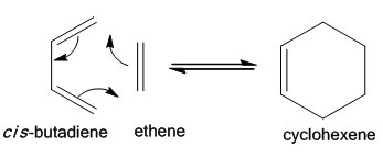
A diels alder reaction is a [4+2] cycloaddition process in which an electron rich conjugated diene bonds to an electron poor dienophile, commonly a substituted alkene, to form a cyclohexene adduct. The reaction involves the cleavage of three π-bonds to form two new σ-bonds between the two reactants and a new π-bond on the diene half of the product. This reaction is said to be a thermal cycloaddition process but there are different mechanisms that are used to describe the reactivity[43]. It can either proceed via a single transition state in a concerted process or a non concerted asynchronous mechanism. Real mechanisms are a mixture of the two.
The first section will focus on modeling transition state structure of the prototyical Diels Alder reaction between butadiene and ethene. Gaussview 5.0 software will be used and similar techniques to those previously used for the cope reaction study will be employed. In addition to the two levels of theory previously used for optimisations, HF/3-21G and DFT/B3LYP/631-G*, a semi-empirical method will also be explored known as AM1.
The second section will analyse a more complex diels alder reaction between a cyclohexadiene and maleic anhydride. This section will pay particular attention to the sereochemistry of the cycloaddition by exploring both the exo- and endo- product formation.
Butadiene and Ethene Cycloaddition
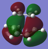
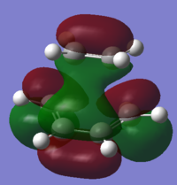
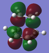
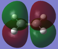
The two π-systems here; butadiene and ethene, contribute 4π and 2π electrons to the system respectively. Ethene's π and π* orbitals and butadiene's HOMO and LUMO are the principle orbitals involved and these can be classified as symmetric or antisymmetric with respect to the plane bisecting the central bond in each.
Optimization and analysis of reactants
Butadiene can exist as two isomers, s-cis and s-trans as well as gauche forms. Only the former is reacts with the dienophile but this form is known to be the higher in energy due to steric repulsion[44].cis-Butadiene and Ethene were both constructed in Gaussview 5.0 and initially optimised using the semi-empirical Austin Model1 (AM1) method. This method uses stored parameters from experimental data such as the ionization energies of atoms or the dipole moments of molecules and omits certain parts of the calculation in an attempt to make it less computationally demanding and more accurate than ab initio methods. Semi-empirical methods work best with systems similar to those that were used to gather experimental data and can be quite erratic with unusual systems. In general, the calculation is more efficient and accurate than using a Hartree-Fock method but less so compared wth than a density funtctional theory calculation.
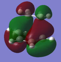
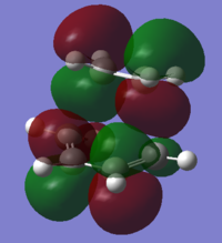
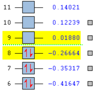
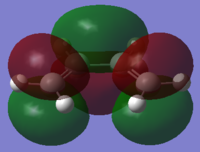
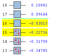
To understand the molecular dynamics involved in the Diels Alder cycloaddition one can simplify the reactivity by focusing on the interactions between the HOMO on one molecule and the LUMO on the other. This approach is the underlying principle behind Frontier Molecular Orbital theory. These generally play the most important role in the bonding that takes place and therefore molecular orbital analysis was then carried out to observe these orbitals on both molecules. Orbital symmetry can be used to determine which orbitals interact as it must be maintained throughout the reaction. The density functional method was used to obtain the orbitals shown bellow and only the HOMO and LUMO were of interest here.
| . | HOMO | LUMO | Relative MO Energies |
|---|---|---|---|
| Ethene | 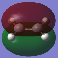
|
|
|
| σv symmetry | symmetric | asymmetric | |
| cis-Butadiene | 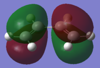
|
|
|
| σv symmetry | asymmetric | symmetric |
The symmetry with respect to the σv mirror planes has been noted. This determines which orbitals interact. Consequently the HOMO on one molecule interacts with the LUMO on the other and vice-versa. This is one reason why the Diels Alder reaction is so successful.
Transition state analysis
To obtain a transition state structure the frozen coordinate method, as used in the Cope rearrangement study, was employed.
The optimised ethene and butadiene molecules were orientated on Gaussview 5.0 at the correct angle to form the transition state. This geometry was used as a guess structure for further reactions. The angle of attack is vitally important to the success of this reaction and careful care was taken to consider how vertical it should be. The angle is similar to that of the Burgi-Dunitz angle and in this case is 102°[45] . The bond lengths were also set to 2.2A and 'frozen' for the initial optimisation at the HF/3-21G level as with the Cope reaction. The partially optimised structure was then optimised to a transition state at the HF/3-21G level with the derivative of the new C-C bonds calculated at every step.
An imaginary vibrational mode at -817.96 cm-1 (note this is exactly the same frequency as the negative vibrational mode for the chair transition state) is the result the structure being a maxima stationary point and therefore indicates the transation optimisation calculation was a success.
IRC analysis shows the energy of the system as a function of the reaction coordinate. The calculation was performed in both directions as the reactants and products were non-symmetrical and using the HF/3-21G method with 100 points along the IRC.
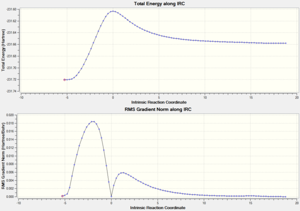
The activation energy for the transition state can be seen clearly and it can also be seen that the product is the thermodynamically less stable molecule. This is expected since there is a loss of conjugation which stabilizes the diene. The gif movie shows the two molecules separating nicely and also towards the end the diene can be seen to twist into the more stable gauche form.
Further optimisation was also performed at both the semi-empirical AM1 level and the more rigorous DFT/B3LYP/6-31G* level. Geometry analysis of the optimised transition state structure for both the method and the method showed notable differences. Firstly the bond angle in the AM1 method is 99.3° which is 3° more vertical than that of the density functional method at 102.3°. The latter is closer to other computed transition stated bond angles found in literature [46] [47](note however that these were also ab initio calculations using a STO-3G and a 4-31G basis set). Both geometries show the diene and dienophile approach each other in a non parrallel plane manner as suggested from experiment[48]. The C-C bond distance for the new σ-bonds being formed is 2.27Å for the DFT method and 2.12 for the AM1 method. These two values are in between the literature value of 2.217Å[49]. This is shorter than a typical C-C bond length at around 1.5Å but crucially shorter than twice the van der waals radiius of a carbon atom. The latter point proves there is a true bonding interaction occurring but that this is a transition state given the bond is not shorter.
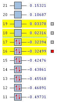
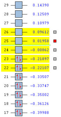
Mo analysis was then carried out using each method. Below is a table of the frontier molecular orbitals as well as 1 above and below the LUMO and HOMO respectively.
The order of the HOMO and HOMO-1 is different depending on the method used. The MOs also appear to differ slightly and DFT method shows small areas of electron density where there is none in the other method, notably in the LUMO and LUMO+1 diagrams. The DFT method is likely to be the more accurate picture for the molecular orbitals since it takes more orbital interactions into account. The reaction mechanism as discussed involves the σ-overlap of two π-clouds of both unsaturated systems. This is evident from the HOMO and HOMO-1 orbitals showing the overlap of the cis-Butadiene π-orbital with the Ethene π* orbital resulting in the two new σ-bonds.
The LUMO shows significant mixing creating regions of shared electron density between the atoms of the fragments.
Maleic Anhydride and Cyclohexa-1,3-diene
Having looked at a prototypical diels alder reaction the study will now focus on the specific example of the reaction between cyclohexa-1,3-diene (the diene) and Maleic anhydride (the dienophile). Particular attention will be paid to the stereoselectivity by building on the MO analysis carried out in the previous section and by using simple symmetry principles and FMO theory.
The total electron count for a Diels alder is 6 (4 π electrons from the diene and 2 π electrons from the dienophile) and the reaction therefore follows the 4n+2 (n=1) Huckel rule. Consequently the reaction must follow Huckel topology and thus involve only suprafacial components.
With the dienophile now being subsituted, the reactants may approach one another from two distinct orientations. The substituent on the dienophile may face away from the diene resulting in the exo stereoisomer or toward the diene resulting in the endo isomer.
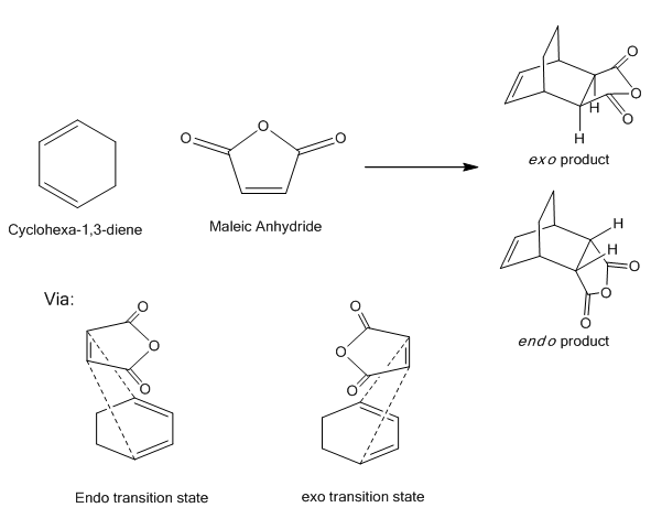
Hoffman proposed that the thermodynamically more stable product is the exo isomer due to the lower steric bulk compared with the endo[50]. However the kinetic product is believed to be the endo isomer and as a result a lower activation energy is expected for this form.
Optimization and analysis of reactants
As with the previous section the reactants Maleic Anhydride and Cyclohexa-1,3-diene were constructed on Gaussview and optimised. These fragments would then be combined to form the transition state. The calculations for this section are all carried out using a DFT/B3LYP/6-31G* level as this was established to be the most accurate method.
Final geometries for both molecules:
MO analysis of reactants
The frontier molecular orbitals on both reactants were analysed to account for the two possible transition states that may form.
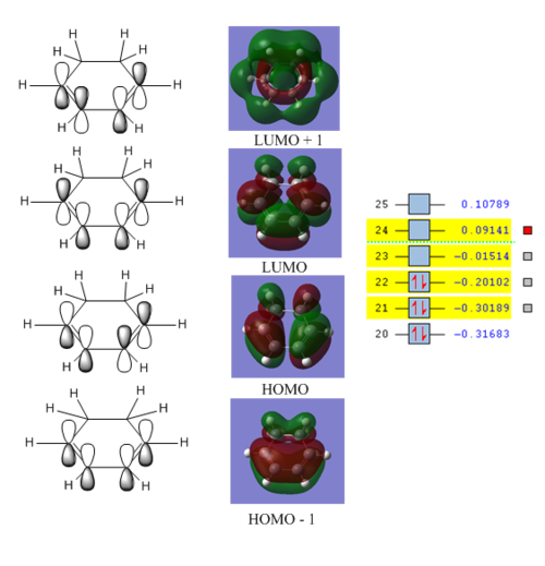
The orbitals matched closely to those predicted through an LCAO MO diagram approach. The important bonding and anti bonding interactions can be clearly accounted for.
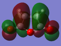
Below shows the orbitals obtained for maleic anhydride.
|
LUMO | 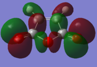
|
HOMO |
Both these orbitals appear to be anti-symmetric with respect to the σv plane of symmetry.
Transition state analysis
The freeze coordinate method was used to construct both transition states from the optimised reactants. The guess structures were formed in a similar manner to the previous Diels-Alder reaction.
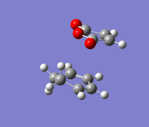
| Transition State | Point Group | Total Energy /Ha | RMS Gradient |
|---|---|---|---|
| [53] | Cs | -612.68339683 | 0.00002161 |
| [54] | Cs | -612.67931096 | 0.00000132 |
This table shows that the endo transition state is the more stable of the two. The explanation as to why this is the more stable structure will be explored using MO analysis later on.
Both transition state structures have one imaginary vibrational mode as expected since they are maxima on the potential energy surface. The endo vibrational mode is at -448.51 cm-1 while the exo vibrates at -447.83 cm-1.
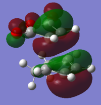
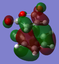
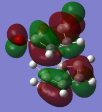
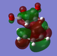
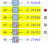
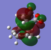
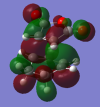
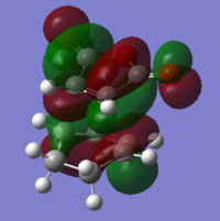
The HOMOs for each isomer are occupied bonding orbitals. As with the prototypical Diels-Alder reaction,the molecular orbitals of the reactants can be used to determine which of them make up the transition state MOs. As discussed previously only the frontier molecular orbitals were considered for this analysis. This oversimplified analysis may not be able to fully account for some of the MOs shown since contributions from lower energy reactant MOs could be present. Both transition state MOs are fairly similar. However evidence of secondary orbital interactions can also be seen from looking at the LUMO+1 orbitals. The carbonyl carbon atom play a part in the bonding through π overlap with the cyclohexene orbitals. This interaction is only present for the endo transition state and has been suggested that this is what gives rise to the regioselectivity of the reaction[55].
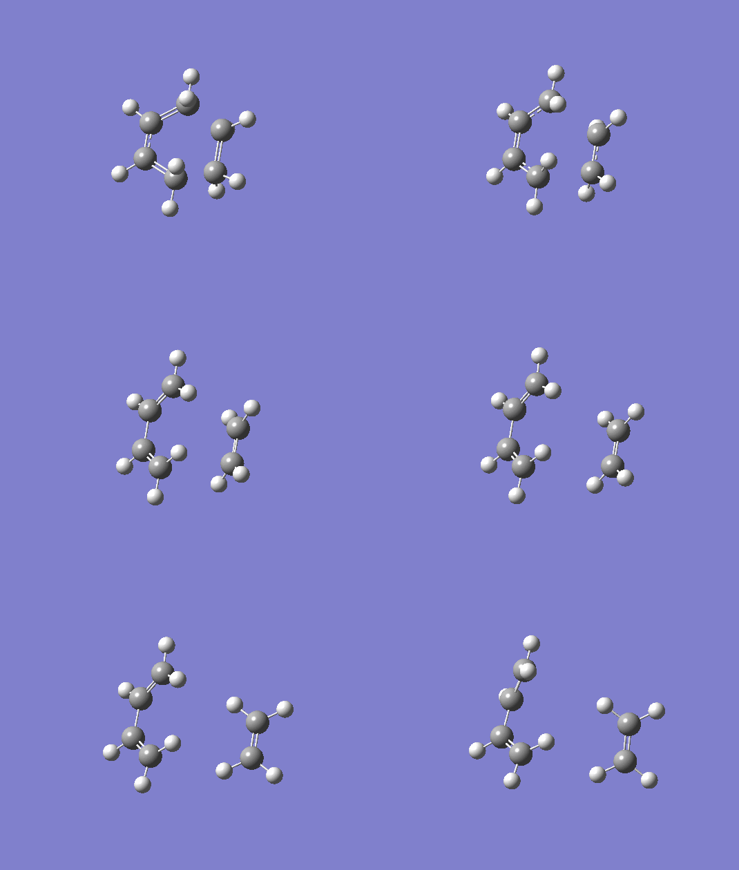
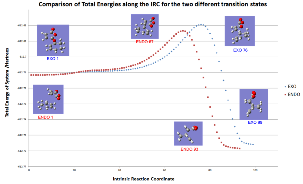
Finally, IRC analysis at the DFT/B3LYP/6-31G* level was able to give an overall picture of the reaction. The data was exported to excel and plotted onto the same graph for comparison and the key data points matched up with the corresponding geometry.
 | |
 |
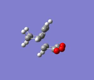 |
| exo product formation | endo product formation |
The graph shows the energy of the transtion state and the energy of the final product are both lower for the endo isomer. Therefore, according to this calculation the endo isomer is both the kinetic and thermodynamic product. The exo product was guessed to be the thermodynamic product and there may be a lack of steric interactions taken into account for this calculation which could destabilise the endo form somewhat. This calculation could be done with an even larger basis set such as the 6-311G*. However the current calculation already took over 12 hours to complete and a larger basis set would create a calculation too time consuming for this project.
The exo transition state is 0.004086 Hartrees higher than the endo form and corresponding to an activation energy that is 2.564Kcal mol-1 higher. This is likely to be because of the secondary orbital interactions stabilising the endo form as discussed previously.
Conclusion
This study has shown the benefits of using computational calculations to study kinetics and transition state theory. Different methods clearly have their strengths and weaknesses and careful consideration should be taken into account when choosing a method for a particular calculation of a given system. Computational methods are clearly very useful for transition state studies given the difficulty in making measurements experimentally because of their short lifetime. However, this powerful tool does have its limitations and inconsistancy with experimental data was seen with the Diels Alder reaction. With ever advancing computer hardware and software, more complex calculations can be undertaken to greater accuracy and consequently this could be a very influential field for chemists in the 21st century especially when used in conjunction with experimental data.
References
- ↑ http://www.ch.ic.ac.uk/local/organic/conf/
- ↑ http://hdl.handle.net/10042/to-4857
- ↑ http://www.ch.ic.ac.uk/local/organic/conf/
- ↑ http://hdl.handle.net/10042/to-13350
- ↑ http://hdl.handle.net/10042/to-13349
- ↑ http://hdl.handle.net/10042/to-13345
- ↑ http://hdl.handle.net/10042/to-13348
- ↑ http://hdl.handle.net/10042/to-13347
- ↑ http://hdl.handle.net/10042/to-13346
- ↑ http://hdl.handle.net/10042/to-13311
- ↑ http://hdl.handle.net/10042/to-13322
- ↑ http://hdl.handle.net/10042/to-13323
- ↑ http://hdl.handle.net/10042/to-13324
- ↑ http://mccammon.ucsd.edu/~blu/Research-Handbook/physical-constant.html
- ↑ http://hdl.handle.net/10042/to-13351
- ↑ http://hdl.handle.net/10042/to-13352
- ↑ http://hdl.handle.net/10042/to-13353
- ↑ http://hdl.handle.net/10042/to-13358
- ↑ http://hdl.handle.net/10042/to-13359
- ↑ http://hdl.handle.net/10042/to-13360
- ↑ J. Coates, Encyclopaedia of Analytical Chemistry, R. A. Meyers (Ed.), 2000, pp 10815 - 10831
- ↑ http://hdl.handle.net/10042/to-13371
- ↑ http://hdl.handle.net/10042/to-13506
- ↑ http://hdl.handle.net/10042/to-13507
- ↑ http://hdl.handle.net/10042/to-13512
- ↑ http://hdl.handle.net/10042/to-13511
- ↑ http://hdl.handle.net/10042/to-13522
- ↑ http://hdl.handle.net/10042/to-13526
- ↑ Calculated on PC
- ↑ http://hdl.handle.net/10042/to-13524
- ↑ http://hdl.handle.net/10042/to-13507
- ↑ http://hdl.handle.net/10042/to-13787
- ↑ http://hdl.handle.net/10042/to-13781
- ↑ http://hdl.handle.net/10042/to-13788
- ↑ http://hdl.handle.net/10042/to-13780
- ↑ http://hdl.handle.net/10042/to-13783
- ↑ http://hdl.handle.net/10042/to-13780
- ↑ http://hdl.handle.net/10042/to-13784
- ↑ http://hdl.handle.net/10042/to-13789
- ↑ http://hdl.handle.net/10042/to-13359
- ↑ http://hdl.handle.net/10042/to-13371
- ↑ 3rd Year Computational Chemistry Online Lab Manual, Module 3, 2011
- ↑ R. B. Woodward, T. J. Katz Tetrahedron , 1959 , 5 , 70 - 89
- ↑ P. G. Szalay, H. Lischka, A. Karpfen, J. Phys. Chem. 1989,93 (18), pp 6629–6631
- ↑ F. Brown, K. Houk Tetrahedron Letters 1984 25, 41, 4609-4612 http://dx.doi.org/10.1016/S0040-4039(01)91212-2
- ↑ F. Brown, K. Houk Tetrahedron Letters 1984 25, 41, 4609-4612 http://dx.doi.org/10.1016/S0040-4039(01)91212-2
- ↑ F. Bernardi, A. Bottoni, M. Robb, J. Am. Chem. Soc.' 1988, Vol. 110, No. 10, http://pubs.acs.org/doi/pdf/10.1021/ja00218a009
- ↑ W. Roush, H. Gillis,J- Am. Chem. Soc., 1982. 1s 2269
- ↑ F. Brown, K. Houk Tetrahedron Letters 1984 25, 41, 4609-4612 http://dx.doi.org/10.1016/S0040-4039(01)91212-2
- ↑ R. Woodward, R. Hoffmann, J. Am Chem. Soc., 87, 1965, pp. 4388-4389
- ↑ http://hdl.handle.net/10042/to-13723
- ↑ http://hdl.handle.net/10042/to-13724
- ↑ http://hdl.handle.net/10042/to-13757
- ↑ http://hdl.handle.net/10042/to-13755
- ↑ I. Fleming, Frontier Orbitals and Organic Chemical Reactions, John Wiley & Sons Ltd, 2002, pp 106 - 108
- ↑ http://hdl.handle.net/10042/to-13785
- ↑ http://hdl.handle.net/10042/to-13786

