
Y3.C2 og108
Year 3 Computational Lab Module 2: Bonding and structure analysis
Oliver Garnett
This module investigates the general structures and energies of various optimized inorganic molecules using Gaussian software. Iorganic systems can prove more computationally demanding due to the wider range of bond lengths, atoms sizes and valencies compared with organic systems. More powerful computational techniques will therefore be employed which can be fine tuned to study many different systems.
Molecular analysis techniques
This section establishes the main techniques used throughout the project for molecular analysis.
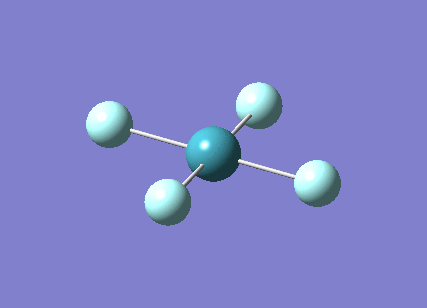
BH3
Geometry optimisation
An optimisation calculation involves the initial evaluation of the energy for a given nuceli position using the Schrodinger equation, this is the Hartree-Fock SCF computation. The geometry is then adjusted slightly and the SCF calculation repeated. The Gaussian compares the two geometries and selects the in lower energy of the two as a starting point for the next SCF computation. The energy will then converge towards a stationary point value after a given number of iterations thus producing the the optimised molecular geometry, this is the OPT part of the calculation.
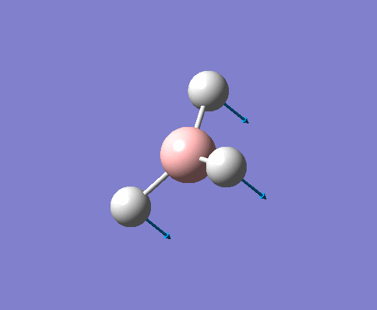
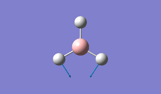
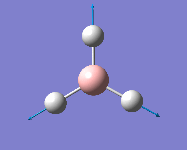
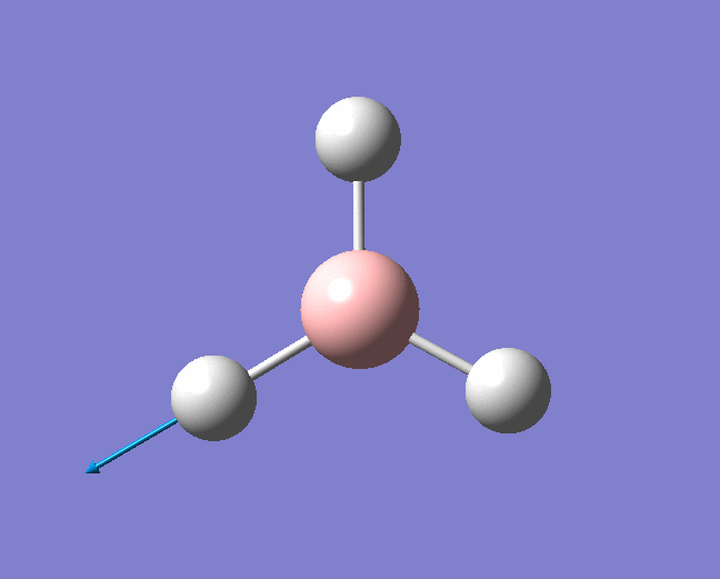
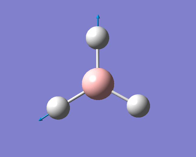
A trigonal planar borane molecule (BH3) was drawn on Gaussview 5.0 and its bonds adjusted to 1.5A. The molecule was then optimized under the B3LYP method, using a 3-21G basis set. The structure of the molecule with bond angles and lengths is shown .
The data of the geometry after optimisation is shown below.
og108 BH3 optimisation
File Name = OG108_BH3_OPTIMISED
File Type = .log
Calculation Type = FOPT
Calculation Method = RB3LYP
Basis Set = 3-21G
Charge = 0
Spin = Singlet
E(RB3LYP) = -26.46226338 a.u.
RMS Gradient Norm = 0.00020672 a.u.
Imaginary Freq =
Dipole Moment = 0.0000 Debye
Point Group = D3H
Job cpu time:  0 days  0 hours  0 minutes  8.0 seconds.
The B-H bond lengths after the optimisation were 1.19Å and H-B-H bond angles of exactly 120.0o, in agreement with the literature. The dipole moment of 0 is a result of the highly symmetrical nature of the trigonal planar molecule which is of the D3H point group.
The LOG file from the calculation shown below confirms the success of the optimisation.
Item               Value     Threshold  Converged?
 Maximum Force            0.000413     0.000450     YES
 RMS     Force            0.000271     0.000300     YES
 Maximum Displacement     0.001610     0.001800     YES
 RMS     Displacement     0.001054     0.001200     YES
 Predicted change in Energy=-1.071764D-06
 Optimization completed.
    -- Stationary point found.
                           ----------------------------
                           !   Optimized Parameters   !
                           ! (Angstroms and Degrees)  !
 --------------------------                            --------------------------
 ! Name  Definition              Value          Derivative Info.                !
 --------------------------------------------------------------------------------
 ! R1    R(1,2)                  1.1935         -DE/DX =    0.0004              !
 ! R2    R(1,3)                  1.1935         -DE/DX =    0.0004              !
 ! R3    R(1,4)                  1.1935         -DE/DX =    0.0004              !
 ! A1    A(2,1,3)              120.0            -DE/DX =    0.0                 !
 ! A2    A(2,1,4)              120.0            -DE/DX =    0.0                 !
 ! A3    A(3,1,4)              120.0            -DE/DX =    0.0                 !
 ! D1    D(2,1,4,3)            180.0            -DE/DX =    0.0                 !
 --------------------------------------------------------------------------------
The data above shows that the root mean squared of the force was minimised to a value below 0.001. This very small value confirms the convergence of the energy to a minimum corresponding to the geometry described above. Further analysis of the graphs for the Total Energy vs optimisation step and the first derivative of the total energy with respect to the optimisation step (RMS gradient norm) vs the optimisation step, show an energy minimum has been reached. A value of 0 for the RMS gradient norm proves an equilibrium has been reached.
 |
 |
Frequency Analysis
Frequency analysis allows the optimised geometry to be confirmed. Observing the second derivative of the potential energy surface determines weather a stationary point (where the RMS is roughly equal to 0) is a maximum or minimum on the potential energy surface which indicates if the optimised molecule corresponds to a transition state or a ground state structure. This is evident from the frequencies of the vibrations, strongly negative values indicated the optimisation has failed or a transition state has been reached rather than a ground state. Frequency analysis using the Gaussian software can also be used to predict the infra-red and raman spectra of a small molecule. A summary of the calculation below:
og108 BH3 frequency
File Name = OG108_BH3_FREQ
File Type = .log
Calculation Type = FREQ
Calculation Method = RB3LYP
Basis Set = 3-21G
Charge = 0
Spin = Singlet
E(RB3LYP) = -26.46226338 a.u.
RMS Gradient Norm = 0.00020662 a.u.
Imaginary Freq = 0
Dipole Moment = 0.0000 Debye
Point Group = C3H
Job cpu time:  0 days  0 hours  0 minutes  7.0 seconds.
It is important to note here that the energy of the structure has not changed. This is the first conformation that the optimised geometry is that of a ground state structure. However Gaussian has given BH3 a C3h point group as opposed to D3h and consequently the symmetry labels have been assigned using this point group. The log output file below also provides some important information:
Full mass-weighted force constant matrix:
 Low frequencies ---  -66.7625  -66.3592  -66.3589   -0.0020    0.0031    0.2123
 Low frequencies --- 1144.1483 1203.6413 1203.6424
 Harmonic frequencies (cm**-1), IR intensities (KM/Mole), Raman scattering
 activities (A**4/AMU), depolarization ratios for plane and unpolarized
 incident light, reduced masses (AMU), force constants (mDyne/A),
 and normal coordinates:
                     1                      2                      3
                    A"                     E'                     E'
 Frequencies --  1144.1483              1203.6413              1203.6424
 Red. masses --     1.2531                 1.1085                 1.1085
 Frc consts  --     0.9665                 0.9462                 0.9462
 IR Inten    --    92.8665                12.3148                12.3173
  Atom  AN      X      Y      Z        X      Y      Z        X      Y      Z
     1   5     0.00   0.00   0.16     0.00   0.10   0.00    -0.10   0.00   0.00
     2   1     0.00   0.00  -0.57     0.00   0.08   0.00     0.81   0.00   0.00
     3   1     0.00   0.00  -0.57    -0.38  -0.59   0.00     0.14   0.38   0.00
     4   1     0.00   0.00  -0.57     0.38  -0.59   0.00     0.14  -0.38   0.00
                     4                      5                      6
                    A'                     E'                     E'
 Frequencies --  2598.4249              2737.4364              2737.4371
 Red. masses --     1.0078                 1.1260                 1.1260
 Frc consts  --     4.0092                 4.9714                 4.9714
 IR Inten    --     0.0000               103.7400               103.7333
  Atom  AN      X      Y      Z        X      Y      Z        X      Y      Z
     1   5     0.00   0.00   0.00     0.11   0.00   0.00     0.00   0.11   0.00
     2   1     0.00   0.58   0.00     0.02   0.00   0.00     0.00  -0.81   0.00
     3   1     0.50  -0.29   0.00    -0.60   0.36   0.00     0.36  -0.19   0.00
     4   1    -0.50  -0.29   0.00    -0.60  -0.36   0.00    -0.36  -0.19   0.00
The low frequencies seen above are those of the center of mass of the molecules and represent the "-6" of the 3N-6 total vibrations. They are clearly an order of magnitude lower than those for the symmetry vibrations however the value of -67cm-1 is still reasonably large and this can be attributed to the small basis set used. The actual modes are all strongly positive, indicative of an energy minima being reach as opposed to a maxima. The 6 vibrational frequencies have been summarised in table XXXX below.
| Vibrational frequency [cm-1] | Literature value[1]* | Relative Intensity | Description | Symmetry Label | Image of vibration | Link to animation |
|---|---|---|---|---|---|---|
| 1144 | 1225 | 92.865 | Out of plane wagging: The hydrogen atoms move above and below the plane of the boron atom in an "umbrella opening" motion. The boron atom is displaced from its equilibrium position while each of the B-H bond lengths remain constant. | A2" |  |
Show Animation |
| 1204 | 1305 | 12.3148 | Symmetric wagging: Two of the B-H bonds scissor from side to side, with each bond length remaining unchanged. The centre of mass does not change during this mode. | E' |  |
Show Animation |
| 1204 | 1305 | 12.3173 | Asymmetric scissoring: Two of the B-H bonds rock in the BH3 plane in a concerted fashion as a BH2 unit. The other H atom rocks in the opposite direction and with a larger amplitude. . | E' |  |
Show Animation |
| 2598 | - | 0 (IR inactive) | Symmetric stretch: All three B-H bonds stretch and compress symmetrically, there is no loss in symmetry and therefore no change in dipole moment. Thus this stretch is IR inactive. | A1' |  |
Show Animation |
| 2737 | 2693 | 103.7400 | Asymmetric stretch: One hydrogen atom remains stationary while the other two B-H bonds stretch asymmetrically with respect to one other. | E' |  |
Show Animation |
| 2737 | 2813 | 103.7333 | Asymmetric stretch: Two of the B-H bonds stretch symmetrically while the remaining B-H bond counteracts this motion in a more exaggerated manner by compressing when the other B-H bonds undergo a symmetric stretch and vice versa. | E' |  |
Show Animation |
- These values are non empirical and are computed using the HF/6-31G method.
The 6 vibrations shown above agree well with literature values. The vibrations only correspond to 3 separate peaks in the IR spectrum , this is because two pairs of vibrations with symmetry label E' are degenerate and one vibration is IR inactive. The stretch with A1' symmetry is fully symmetrical and therefore there is no change in dipole moment and does not absorb IR radiation.
 |
Molecular Orbital analysis
Using the formatted checkpoint file from the inital optimisation of borane further calculations were performed to obtain quantitative MO's which could be observed using the gaussian software. The energy calculation was performed using the B3LYP method and a 3-21G basis set, as before but including the parameters "pop=(full,nbo)" as well.
LCAO theory can be used to create a molecular orbital diagram that gives a qualitative view of the bonding interactions. This in conjunction with the calculations carried out can give an accurate representation of the bonding of BH3. The first 8 molecular orbitals of borane are shown.
 |
 |
It can be seen from figure XXXX that the bonding orbitals predicted through LCAO correspond well to the calculated MOs. The relative energies in Hartrees of each orbital and general electronic configuration has been shown in figure XXXX. The LCAO method can struggle to predict the relative energies of the MOs since it is based on qualitative arguments. In this case, the order of the LUMO +1,LUMO+2 and LUMO+3 were difficult to establish and computational methods have been particularly useful in this instance. The relative energy value for each orbital shows that orbitals 7 and 8 (LUMO +2 and LUMO +3 respectively) are anti-bonding and degenerate with an energy of +0.17954 Hartrees. Through observation these have been assigned the 2e' symmetry label while the slightly lower energy orbital 6 has been assigned 3a1' . Note the extremely low relative energy of the non-bonding Boron 1s orbital relative to the remaining MO's, this has been included in the MO diagram but is clearly not to scale.
Natural Bond Orbital analysis
The calculation performed to observe the molecular orbitals can also allow the Natural Bond Orbitals and Charge Distribution within the molecule to be analysed. NBO analysis offer a localized view of the bonding as opposed to MOs which give a delocalized picture. Gaussview 5.0 provides a graphical interface for charge distribution of the the molecule shown using the color coded charge distribution diagram in Figure XXXX.
 |
 |
Key data from the output .log file from the energy calculation can be seen below:
(Occupancy)   Bond orbital/ Coefficients/ Hybrids
 ---------------------------------------------------------------------------------
     1. (1.99854) BD ( 1) B   1 - H   2
                ( 45.36%)   0.6735* B   1 s( 33.33%)p 2.00( 66.67%)
                                            0.0000  0.5774  0.0000  0.0000  0.0000
                                            0.8165  0.0000  0.0000  0.0000
                ( 54.64%)   0.7392* H   2 s(100.00%)
                                            1.0000  0.0001
     2. (1.99854) BD ( 1) B   1 - H   3
                ( 45.36%)   0.6735* B   1 s( 33.33%)p 2.00( 66.67%)
                                            0.0000  0.5774  0.0000  0.7071  0.0000
                                           -0.4082  0.0000  0.0000  0.0000
                ( 54.64%)   0.7392* H   3 s(100.00%)
                                            1.0000  0.0001
     3. (1.99854) BD ( 1) B   1 - H   4
                ( 45.36%)   0.6735* B   1 s( 33.33%)p 2.00( 66.67%)
                                            0.0000  0.5774  0.0000 -0.7071  0.0000
                                           -0.4082  0.0000  0.0000  0.0000
                ( 54.64%)   0.7392* H   4 s(100.00%)
                                            1.0000  0.0001
     4. (1.99954) CR ( 1) B   1           s(100.00%)
                                            1.0000  0.0000  0.0000  0.0000  0.0000
                                            0.0000  0.0000  0.0000  0.0000
     5. (0.00000) LP*( 1) B   1           s(100.00%)
etc...
NBO analysis divides the electron density of the entire molecule into 28 natural atomic orbitals (NAOs) which are then used to form 2 centre-2 electron bonds. The log file above shows that the first 3 NBOs are 2-centre bonds (denoted BD) and that the hydrogen atoms, which are 100% s orbital character, contribute 55.5% towards the bonding are while boron, a natural atomic hybrid with 33.33% s character and 66.67% p character, only contributes 44.5%. This indicates that 3 sp2 hybrid orbitals interact with the s atomic orbitals of each Hydrogen atom. Orbital 4 is a core (CR) Boron 1s AO and is known to be non-bonding as shown in the MO diagram previously shown. The 5th orbital has been denoted "LP*" which implies the orbital contains a lone pair and is 100% p character. However this orbital is known to be formally unoccupied demonstrating the limitations of the software.
Second-order peturbative estimates of donor-acceptor interactions can been seen from the part of the .out flie shown below. This is carried out by examining all the possible interactions between the filled Lewis type NBOs and the empty non-lewis NBOs and then estimating their energetic importance. This represents secondary orbital interactions that involve the delocalisation of charge. The interactions calculated are all very low and therefore no significant 2nd order orbital mixing occurs.
None exceeding thresholds


 Second Order Perturbation Theory Analysis of Fock Matrix in NBO Basis

     Threshold for printing:   0.50 kcal/mol
                                                                              E(2)  E(j)-E(i) F(i,j)
         Donor NBO (i)                     Acceptor NBO (j)                 kcal/mol   a.u.    a.u.
 within unit  1
   4. CR (   1) B   1                / 10. RY*(   1) H   2                    0.70    7.42    0.064
   4. CR (   1) B   1                / 11. RY*(   1) H   3                    0.70    7.42    0.064
   4. CR (   1) B   1                / 12. RY*(   1) H   4                    0.70    7.42    0.064
A total of 15 NBOs are given which correspond to the 15 AOs that make up the split-valence basis set used for the calculation. The remaining orbitals are unoccupied and little information can be gained from their analysis so have not been included in the table above. The summary section indicates the energies and occupancies of the relevant orbitals:
Natural Bond Orbitals (Summary):

                                                            Principal Delocalizations
           NBO                        Occupancy    Energy   (geminal,vicinal,remote)
 ====================================================================================
 Molecular unit  1  (H3B)
     1. BD (   1) B   1 - H   2          1.99854    -0.43328
     2. BD (   1) B   1 - H   3          1.99854    -0.43328
     3. BD (   1) B   1 - H   4          1.99854    -0.43328
     4. CR (   1) B   1                  1.99954    -6.68393  10
TlBr3
Geometry optimization
A molecule of thallium tribromide was drawn using the Gaussian software in a similar fashion to that for the borane molecule. An optimisation calculation was also carried out using the method DFT/B3LYP but with the medium level basis sets of the LanL2DZ option. The method involves the use of pseudo potentials which model the core electrons on a single function and enable the calculation to be based solely on the valence shell electrons. The use of pseudo potentials significantly simplifies the calculation but the assumption is only valid for large atoms such as Thallium. The optimised structure can be viewed and a summary of the calculation can be seen below.
og108_TlBr3_optimisation
File Name = og108_TlBr3_optimisation
File Type = .log
Calculation Type = FOPT
Calculation Method = RB3LYP
Basis Set = LANL2DZ
Charge = 0
Spin = Singlet
E(RB3LYP) = -91.21812851 a.u.
RMS Gradient Norm = 0.00000090 a.u.
Imaginary Freq =
Dipole Moment = 0.0000 Debye
Point Group = D3H
Job cpu time:  0 days  0 hours  0 minutes 17.0 seconds.
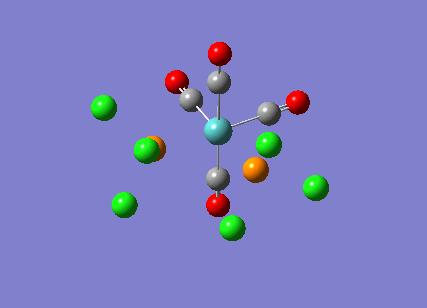
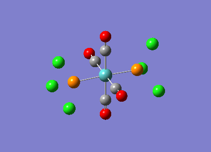
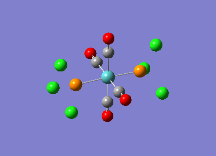
The Tl-Br bond lengths after the optimisation were 2.65Å and Br-Tl-Br bond angles of exactly 120.0o, in agreement with the literature.
 |
 |
Frequency analysis
The vibrational modes for TlBr3 were calculated with the same method and basis set as for the optimisation calculation to confirm a ground state structure. A summary of the calculation can be seen below:
Filename = //icfs16.cc.ic.ac.uk/og108/Desktop/Labs/3rd Year Labs/Computational/Module 2/part 1/TlBr3/output/og108_Tlbr3_freq1.chk

TlBr3 frequency1
File Name = og108_Tlbr3_freq1
File Type = .chk
Calculation Type = FREQ
Calculation Method = RB3LYP
Basis Set = LANL2DZ
Charge = 0
Spin = Singlet
Total Energy = -91.21812851 a.u.
RMS Gradient Norm = 0.00000088 a.u.
Imaginary Freq = 0
Dipole Moment = 0.0000 Debye
Point Group =
The increased accuracy of the LANL2DZ basis set compared with the B3YLP basis set is evident from the low values for the low frequency "-6" vibrations shown in the log file, which are all between -5cm-1 and +5cm-1. This also proves the success of the optimisation.
Full mass-weighted force constant matrix:
 Low frequencies ---   -3.4213   -0.0026   -0.0004    0.0015    3.9367    3.9367
| Vibrational frequency [cm-1] | Literature value[2]* | Relative Intensity | Description | Symmetry Label | Image of vibration | Link to animation |
|---|---|---|---|---|---|---|
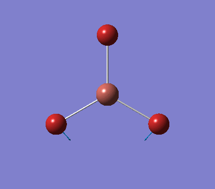
| 46 | 4 | 3.687 | Symmetric wagging: Two of the Tl-Br bonds scissor from side to side, with each bond length remaining unchanged. The center of mass does not change during this mode. | E' |  |
Show Animation |
| 46 | 4 | 3.687 | Asymmetric scissoring: Two of the Tl-Br bonds rock in the TlBr3 plane in a concerted fashion as a TlBr2 unit. The other Br atom rocks in the opposite direction and with a larger amplitude. | E' |  |
Show Animation |
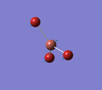
| 52 | 6 | 5.847 | Out of plane wagging: The bromine atoms move above and below the plane of the thallium atom in an "umbrella opening" motion. The thallium atom is displaced from its equilibrium position while each of the Tl-Br bond lengths remain constant. | A2" |  |
Show Animation |
| 165 | - | 0 (IR inactive) | Symmetric stretch: All three Tl-Br bonds stretch and compress symmetrically, there is no loss in symmetry and therefore no change in dipole moment. Thus this stretch is IR inactive. | A1' |  |
Show Animation |
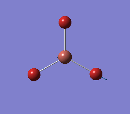
| 211 | 220 | 25.483 | Asymmetric stretch: One bromine atom remains stationary while the other two Tl-Br bonds stretch asymmetrically with respect to one other. | E' |  |
Show Animation |
| 211 | 220 | 25.480 | Asymmetric stretch: Two of the Tl-Br bonds stretch symmetrically while the remaining Tl-Br bond counteracts this motion in a more exaggerated manner by compressing when the other Tl-Br bonds undergo a symmetric stretch and vice versa. | E' |  |
Show Animation |
- The literature values obtained are for an aqueous solution.
The calculated vibrational modes are very similar to those of borane as expected since BH3 is also a D3h molecule. The low intensity of the wagging and scissoring motions mean they are often probably not observed in reality. The calculated frequencies for the two asymmetric stretches correspond well with the literature values for aqueous TlBr3. The symmetric stretch is IR inactive as discussed with borane.
The predicted IR spectrum can be seen below:
 |
Defining a chemical bond
Gaussview indicates a chemical bond by drawing a line between two atoms and will remove this line when the inter-nuclei distance exceeds a set value or does not match a vlue in their database. This is common for inorganic molecules since gaussian's internal list of bond lengths mainly consists of organic molecules with shorter bond distances. However our chemical intuition should tell us that using the distance between two nuceli to define a chemical bond is insufficient. In reality a bond can be seen as an attraction between two atoms resulting in a mimimum energy well, in which neither atoms expireience a net force and are said to be in equillibrium. There are many different bond types; ionic, convalent, metallic, hydrogen bonds etc. which depend on the intrinsic properties of the atoms involved[3].
Stereoisomerism of Mo(CO)4P(Cl3)2
The cis-/ trans- isomerism of Mo(CO)4P(Cl3)2 was under study to investigate the bonding in each. Both isomers underwent three seperate optimisations using varying sizes of basis set to obtain an accurate geometry for the ground state strucutre. Frequency analysis then confirmed the geometries obtained and allowed more detailed bonding comparisons to be made.
cis-Mo(CO)4P(Cl3)2
Geometry optimisation
The first optimisation was accomplished using a "loose" basis set which provided a reasonable starting point to obtain a more accurate geometry. This initial calculation was performed with a B3LYP/LANL2MB method to give a rough geometry. The parameter "opt=loose" was employed which lowered the convergence critera to a RMS force of 0.0017 au and maximum step size of 0.01au. The cis- isomer can be seen
Filename = //icfs16.cc.ic.ac.uk/og108/Desktop/Labs/3rd Year Labs/Computational/Module 2/part 2/cis/output/og108_cisMo_optimisation_loose1.out

Cis Mo optimisation loose
File Name = og108_cisMo_optimisation_loose1
File Type = .log
Calculation Type = FOPT
Calculation Method = RB3LYP
Basis Set = LANL2MB
Charge = 0
Spin = Singlet
E(RB3LYP) = -617.52473214 a.u.
RMS Gradient Norm = 0.00028751 a.u.
Imaginary Freq =
Dipole Moment = 8.7911 Debye
Point Group = C1
Job cpu time:  0 days  0 hours  8 minutes 57.4 seconds.
A stationary point was found after 9 iterations which can viewed in the Gaussian log file from SCAN [4].
The loose optimisation produced a structure The Cl-P-Mo-C(axial) dihedral angle for the upward pointing axial carbon of the loosely optimised molecule was adjusted manually to 0 and this was done for the other -cis ligand but with the axial carbon pointing down. This aided the convergence and allowed the calculation to be less time consuming.
Further optimisation was then carried out using the same B3LYP method but with a LanL2DZ (double zeta) basis set. Additional permaters were added; "int=ultrafine" and "scf=conver=9", to make the convergence critera more strict. This yielded the following and the calculation summary can be seen below.
Filename = //icfs16.cc.ic.ac.uk/og108/Desktop/Labs/3rd Year Labs/Computational/Module 2/part 2/cis/output/og108_cisMo_optimisation_loose1.out

Cis Mo optimisation loose
File Name = og108_cisMo_optimisation_loose1
File Type = .log
Calculation Type = FOPT
Calculation Method = RB3LYP
Basis Set = LANL2MB
Charge = 0
Spin = Singlet
E(RB3LYP) = -617.52473214 a.u.
RMS Gradient Norm = 0.00028751 a.u.
Imaginary Freq =
Dipole Moment = 8.7911 Debye
Point Group = C1
Job cpu time:  0 days  0 hours  8 minutes 57.4 seconds.
This time the stationary point was found after 11 iterations[5].
The 3d orbital on Phosphorus is relatively low in energy and therefore can participate in bonding with Mo and Cl. Neglecting the d-orbital interactions as the previous two methods have done would therefore produce a weaker and consequently longer bond. As a result a final optimisation was carried out including a d-orbital situated on the phosphorus atom. This is was done by editing the input file with the following additions:
# opt b3lyp/lanl2dz geom=connectivity int=ultrafine scf=conver=9 extrabasis
P 0
D 1 1.0
0.55 0.100D+01
****
The final optimised geometry from this calculation was found after 6 iterations[6] and can be seen and a copy of the log file below.
Filename = //icfs16.cc.ic.ac.uk/og108/Desktop/Labs/3rd Year Labs/Computational/Module 2/part 2/cis/output/og108_cisMo_optimisation_tightdAO1.out

Cis Mo optimisation tightdAO1
File Name = og108_cisMo_optimisation_tightdAO1
File Type = .log
Calculation Type = FOPT
Calculation Method = RB3LYP
Basis Set = Gen
Charge = 0
Spin = Singlet
E(RB3LYP) = -623.69291202 a.u.
RMS Gradient Norm = 0.00005680 a.u.
Imaginary Freq =
Dipole Moment = 0.0709 Debye
Point Group = C1
Job cpu time:  0 days  0 hours 37 minutes 36.1 seconds.
These results are discussed and compared with those of the trans- isomer in the vibrational summary section.
vibrational analysis
The new geometry was submitted to SCAN[7] for frequency analysis to confirm the success of the optimisation calculation. Further frequency analysis using the LANL2DZ d modified basis set was also carried out to obtain more accurate results[8]. The excerpt from the log files shows no significantly negative values in the low frequency range:
Initial frequency analysis:
Low frequencies ---   -1.7505   -0.0005   -0.0005   -0.0004    1.2490    1.3208
 Low frequencies ---   10.7781   17.6458   42.0423
Advanced frequency analysis:
Low frequencies ---   -1.2533   -0.0008   -0.0006   -0.0005    0.8185    1.9593
 Low frequencies ---   11.7478   20.2858   45.8857
Comparison of the above indicates the slight improvement in accuracy as the most negative low frequency value is closer to zero.
The cis- isomer is of the C2v point group and using this the various vibrational modes of the molecules have been assigned shown below in table XXXX
| Vibrational frequency (LANL2DZ) [cm-1] | Vibrational frequency (LANL2DZ + dAO) [cm-1] | Literature value[9] | Relative Intensity | Description | Symmetry Label | Link to animation |
|---|---|---|---|---|---|---|
| 11 | 12 | - | 0.026 | Symmetrical rotation of the PCl3 groups around the Mo-P bond. | - | Show Animation |
| 18 | 20 | - | 0.008 | Synchronised rotation of the PCl3 groups around the Mo-P bond. | - | Show Animation |
| 1946 | 1938 | 1869 | 739.637 | Asymmetrical stretch of the two carbonyls one which is trans- to PCl3 and one which is cis- | B2 | Show Animation |
| 1948 | 1941 | 1896 | 1491.952 | Asymmetrical stretch of the two carbonyls which are both cis- to PCl3 | B2 | Show Animation |
| 1958 | 1952 | 1924 | 627.723 | Two pairs of carbonyls stretch symmetrically with respect to one another. | A1 | Show Animation |
| 2023 | 2019 | 2026 | 602.727 | All four carbonyls stretch symmetrically with respect to one another. | A1 | Show Animation |
The lowest frequency modes correspond to motion of the Mo-P bond. This is expected as we know from the the simple harmonic oscillator equation that the reduced mass is inversely proportional to the reduced mass and the Mo-P reduced mass is large.
The carbonyl region is of particular interest as it displays the backbonding effects that occur and consequently can be used to distinguish which isomer is present. These values match closely with the literature and in the case of the cis- isomer produce 3 noticeable peaks which correspond to the different IR active vibrations. There are in fact 4 different IR modes but the two B2 modes are too close in energy to distinguish properly.
The predicted IR spectrum can be seen below:
 |
 |
trans-Mo(CO)4P(Cl3)2
Geometry optimisation
The trans isomer geometry from the initial loose optimisation was obtained after 7 iterations [10] and can be seen
Filename = //icfs16.cc.ic.ac.uk/og108/Desktop/Labs/3rd Year Labs/Computational/Module 2/part 2
/trans/output/og108_transMo_optimisation_loose1.out

transMo optimisation loose1
File Name = og108_transMo_optimisation_loose1
File Type = .log
Calculation Type = FOPT
Calculation Method = RB3LYP
Basis Set = LANL2MB
Charge = 0
Spin = Singlet
E(RB3LYP) = -617.52198652 a.u.
RMS Gradient Norm = 0.00116777 a.u.
Imaginary Freq =
Dipole Moment = 0.0000 Debye
Point Group = CI
Job cpu time:  0 days  0 hours  4 minutes  3.9 seconds.
The geometry of the trans- isomer was then adjusted so that the two PCl3 ligands were eclipsed, also ensuring that one P-Cl bond was parallel to a Mo-C bond on each PCl3 ligand to aid the energy convergence.
Further optimisation was then carried out using in the same manner as for the cis- isomer. This yielded the following after 9 iterations[11] and the calculation summary can be seen below.
Filename = //icfs16.cc.ic.ac.uk/og108/Desktop/Labs/3rd Year Labs/Computational/Module 2/part 2
/trans/output/og108_transMo_optimisation_loose1.out

transMo optimisation loose1
File Name = og108_transMo_optimisation_loose1
File Type = .log
Calculation Type = FOPT
Calculation Method = RB3LYP
Basis Set = LANL2MB
Charge = 0
Spin = Singlet
E(RB3LYP) = -617.52198652 a.u.
RMS Gradient Norm = 0.00116777 a.u.
Imaginary Freq =
Dipole Moment = 0.0000 Debye
Point Group = CI
Job cpu time:  0 days  0 hours  4 minutes  3.9 seconds.
The 3d orbital on Phosphorus is realtivetly low in energy and therefore can participate in bonding with Mo and Cl. Neglecting the d-orbital interactions as the previous two methods have done would therefore produce a weaker and consequently longer bond. As a result a final optimisation was carried out including the d-orbitals. This is was done by editing the input file with the following additions:
# opt b3lyp/lanl2dz geom=connectivity int=ultrafine scf=conver=9 extrabasis
P 0
D 1 1.0
0.55 0.100D+01
****
The final optimised geometry taking d orbital effects can be seen this was achieved after 8 iterations[12] and a summary of the calculation is shown below.
Filename = //icfs16.cc.ic.ac.uk/og108/Desktop/Labs/3rd Year Labs/Computational/Module 2/part 2/trans/output/og108_transMo_optimisation_tightdAO1.out

transMo optimisation tight dAO
File Name = og108_transMo_optimisation_tightdAO1
File Type = .log
Calculation Type = FOPT
Calculation Method = RB3LYP
Basis Set = Gen
Charge = 0
Spin = Singlet
E(RB3LYP) = -623.69415608 a.u.
RMS Gradient Norm = 0.00000942 a.u.
Imaginary Freq =
Dipole Moment = 0.2293 Debye
Point Group = C1
Job cpu time:  0 days  0 hours 41 minutes 41.0 seconds.
See later for analysis of these values.
vibrational analysis
The vibrational analysis for the trans isomer yielded the following vibrational modes which can be seen in table X. The log file[13] was also used gauge the success of the optimisation. Further frequency analysis using the LANL2DZ d modified basis set was also carried out to obtain more accurate results[14]. The excerpt from the log files shows no significantly negative values in the low frequency range:
Initial frequency analysis:
Low frequencies ---   -2.2210   -1.8923   -0.0004   -0.0001    0.0005    2.5284
 Low frequencies ---    5.0835    6.1927   37.2048
Advanced frequency analysis:
Low frequencies ---   -2.2978   -1.9633   -0.0003   -0.0002    0.0001    2.8529
 Low frequencies ---    4.5720    7.0033   40.4799
From comparison of the above excerpts no real improvement can be seen however this is only a small indicator of increased accuracy of the calculation. Further analysis of the vibrational frequencies will give a better idea of the accuracy of the revised basis set.
| Vibrational frequency (LANL2DZ) [cm-1] | Vibrational frequency (LANL2DZ + dAO) [cm-1] | Literature value[15] | Relative Intensity | Description | Symmetry Label | Link to animation |
|---|---|---|---|---|---|---|
| 5 | 4 | - | 0.094 | Symmetrical rotation of the PCl3 groups around the Mo-P bond. | - | Show Animation |
| 6 | 7 | - | 0.000 | Asymmetrical rotation of the PCl3 groups around the Mo-P bond. | - | Show Animation |
| 1951 | 1939 | 1886 | 1475.581 | Asymmetrical stretch of the two carbonyls one which is trans- to one another. The remaining carbonyls are stationary. | E1u | Show Animation |
| 1951 | 1940 | 1886 | 1466.782 | Asymmetrical stretch of one pair of carbonyls trans- to one another while the reamianing pair of carbonyls stretch symmetrically | E1u | Show Animation |
| 1978 | 1967 | 1933 | 0.567 | Two pairs of carbonyls stretch symmetrically with respect to one another. | B1g | Show Animation |
| 2031 | 2025 | 2050 | 3.68 | All four carbonyls stretch symmetrically with respect to one another. | A1g | Show Animation |
The predicted IR spectrum can be seen below:
These results are discussed and compared with those of the cis- isomer in the vibrational summary section.
Summary of optimisation calculations
The bond lengths for both isomers have been tablulated and compared to literature X-ray crystallography values as seen in table XXXX below.
| Diatomic Bond | cis- Isomer Bond Length** (Å) | trans- Isomer Bond Length (Å) | ||||||
|---|---|---|---|---|---|---|---|---|
| LANL2MB | LANL2DZ | LANL2DZ including d AO | Literature[16]* Value | LANL2MB | LANL2DZ | LANL2DZ including d AO | Literature[17] Value | |
| Mo-C | 2.11 | 2.06 | 2.05 | 2.01 | 2.11 | 2.06 | 2.06 | 1.87 |
| C-O | 1.19 | 1.17 | 1.17 | 1.15 | 1.19 | 1.17 | 1.17 | 1.15 |
| Mo-P | 2.53 | 2.51 | 2.48 | 2.58 | 2.48 | 2.44 | 2.42 | 2.37 |
| P-Cl | 2.40 | 2.24 | 2.11 | 1.83 | 2.40 | 2.24 | 2.12 | - |
- The exact complex was unable to be found for bond analysis so cis- isomer has been compared with cis-Mo(CO)4(PPH3)2 instead.
- Please also note that the carbonyl ligands trans to the PCl3 groups were used for the Mo-C and C-O measurements. Trans effects have been discussed separately below.
The bond distances correlate well to the literature values. The effect of varying size of the basis set on the accuracy of the calculated geometry can be shown via the increasing agreement with the literature with increase in basis set. The difference is particularly apparent for the P-Cl bond when including the d-orbitals in the optimisation, as seen from the large difference in bond length length.
Evidence for the trans effect arises through analysis of the Mo-C and C-O bond lengths for the cis- isomer. The effect in this case is caused by Phosphorus donating electron density onto the metal centre inducing greater backbonding from the metal onto the trans- carbonyl ligand. This causes a slightly shorter Mo-C bond distance of 2.02 A for the carbonyl trans- to the phousphorus as opposed to 2.05A for th carbonyl trans- to P . The same back donation lengthens the C-O bond slightly (1.18A instead of 1.17A) since the carbon accepts electron density into a pi-star antibonding orbital. Note that the bond distances given here were taken from optimisation using the B3LYP/LanD2Z method with dAOs included.
The energies of each isomer using different methods have also been tabulated. It appears that the trans- isomer is the lowest energy form by 0.0012 Hartrees which is about 3.27kJmol-1.
| LANL2DZ (hatree) | LANL2DZ including d AO (hatree) | |
|---|---|---|
| cis- isomer | -617.52473214 | -623.69291202 |
| trans- isomer | -617.521986652 | -623.69415608 |
The increased stability of the trans- isomer is also evident from thermal isomerisation which gives rise to the more thermodynamically stable isomer. Though the difference in energy is small, the fact that the cis- isomer can be isolated implies a significant barrier for the interconversion must exist[18] .
Summary of Vibrational analysis
The low frequency vibrational modes arise from -PCl3 rotations and cause very little change in dipole moment, hence the low frequency observed. Other low frequency modes are related to the molybdenum centre which has a large reduced mass and consequently will vibrate at a low frequency. At room temperature KBT~200cm-1 and so these low frequency modes will be excited.
The LAN2DZ basis set with dAO situated on phosphorus shows a clear improvement in accuracy since the vibrational frequencies are all closer to their literature values. This is particularly apparent for Mo-P vibrational modes which are increased since inclusion of dAO's strengthens the Mo-P bond.
Above 1900cm-1 the C-O stretching modes are observed. The carbonyl region is of particular interest as it displays the backbonding effects that occur and consequently can be used to distinguish which isomer is present. The values in this region match closely with the literature for both isomers. In the case of the cis- isomer 3 noticeable peaks are produced which correspond to the different IR active vibrations. There are in fact 4 different IR modes but the two B2 modes are too close in energy to distinguish properly. The varying vibrational frequencies arise from the trans- effects discussed in the previous section which cause a weakening of the C-O bond via electron density filling the pi* orbital. This results in a lower frequency of vibration for carbonyls trans to a PCl3 compared to being trans to another carbonyl. Clearly in the trans- isomer the carbonyls are all trans- one another so all have the same vibrational mode. Hence one peak is observed.
Mini Project: Comparison of the bonding in Xenon Fluoride compounds
Since the initial discovery of XePtF6 in 1962[19] many different noble gas compounds have been synthesized and characterized. The Xenon Fluorides are particularly interesting, the most stable of which are the colorless gases; XeF2, XeF4, and XeF6. Their unexpected stability violates the octet rule and therefore has attracted much attention from both theoretical and experimental oriented chemists. Xenon Fluorides were found to resemble hypervalent halides of other molecules and are strong oxidizing agents.
The direct reaction of xenon with fluoride leads to XeF2 XeF4 and XeF6 with oxidation states +2, +4 and +6 respectively [20]. Structures of XeF2 and XeF4 have been well established from diffraction and spectroscopic methods but the same analysis of XeF6 indicates it is fluxional. The two structures of XeF4 and XeF6 will be compared using similar methods as used earlier in this module.
Optimisations
The varying sizes of the atoms in these molecules required a b3lyp/gen method to be used which allowed varying sizes of basis set to be incorporated into the calculation. The large size of xenon means that in order for an ab initio calculation to be executed, pseudo potentials techniques must be implemented to make it less computational demanding. Therefore the lanL2DZ basis set was used for this atom. The smaller fluorine atoms can be evaluated with a full basis set which in this case was at the 6-31 +G(D) level. This is also a large basis set allowing for more accurate optimisations to be achieved. This was achieved by editing the input file with the following additions:
f 0
6-31+g(d)
****
Xe 0
lanl2dz
****

Xe 0
lanl2dz
Convergence criterea and other perameters were also added to the calculation, namely "pseudo=read gfprint scf=conver=9 int=ultrafine".
For XeF4 a stationary point was reached after 6 iterations as seen in the log file[21] the optimised geometry can be seen . The summary of the calculation has been shown below:
Filename = //icfs16.cc.ic.ac.uk/og108/Desktop/Labs/3rd Year Labs/Computational/Module 2/
part 3/XeF4/output/og108_Xef4_optimisation_tight1.out

XeF4 optimisation tight
File Name = og108_Xef4_optimisation_tight1
File Type = .log
Calculation Type = FOPT
Calculation Method = RB3LYP
Basis Set = Gen
Charge = 0
Spin = Singlet
E(RB3LYP) = -414.50732125 a.u.
RMS Gradient Norm = 0.00010206 a.u.
Imaginary Freq =
Dipole Moment = 0.0000 Debye
Point Group = D4H
Job cpu time:  0 days  0 hours  1 minutes 13.8 seconds.
For XeF6 a stationary point was reached after 7 iterations as seen in the log file[22] the optimised geometry can be seen . The summary of the calculation has been shown below:
Filename = //icfs16.cc.ic.ac.uk/og108/Desktop/Labs/3rd Year Labs/Computational/Module 2/part 3/XeF6/output/og108_Xef6_optimisation_tight2.out

XeF6 optimisation tight
File Name = og108_Xef6_optimisation_tight2
File Type = .log
Calculation Type = FOPT
Calculation Method = RB3LYP
Basis Set = Gen
Charge = 0
Spin = Singlet
E(RB3LYP) = -614.00616205 a.u.
RMS Gradient Norm = 0.00000836 a.u.
Imaginary Freq =
Dipole Moment = 0.0000 Debye
Point Group = OH
Job cpu time:  0 days  0 hours  2 minutes 35.9 seconds.
From these optimized structures Xenon tetra fluoride appears to have a longer Xe-F bond of 2.02A, compared with the octahedral XeF6 which has a 1.99A bond length. Experimental values for these bonds are 1.89A[23] for XeF6 and 1.95A[24] for XeF4 (it is important to note that this measurement was for the crystal structure and therefore may be influenced by intermolecular interactions which are not taken into account in these calculations). This is because the both atoms have the same Xe-F bond order but XeF4 has a lower oxidation state than XeF6.
Frequency analysis
Frequency analysis confirmed the success of the optimisations. A excerpts of the low frequencies from the log file show no strongly negative values (XeF6[25] and XeF4[26])
XeF6
Low frequencies ---  -11.3658  -11.3658  -11.3658    0.0009    0.0012    0.0013
 Low frequencies ---   60.7954   60.7954   60.7954
XeF4
Low frequencies ---  -13.0373  -11.9153  -11.9153   -0.0013   -0.0010   -0.0006
 Low frequencies ---  118.7586  118.7586  139.7225
Only the IR active frequencies have been tabulated here.
| Vibrational frequency [cm-1] | Literature value[27] | Relative Intensity | Symmetry Label | Link to animation |
|---|---|---|---|---|
| 61 | - | 0.086 | T1u | Show Animation |
| 61 | - | 0.086 | T1u | Show Animation |
| 61 | - | 0.086 | T1u | Show Animation |
| 518 | 610 | 244 | T1u | Show Animation |
| 518 | 610 | 244 | T1u | Show Animation |
| 518 | 610 | 244 | T1u | Show Animation |
| Vibrational frequency [cm-1] | Literature value[28] | Relative Intensity | Symmetry Label | Link to animation |
|---|---|---|---|---|
| 119 | 161 | 1.950 | Eu | Show Animation |
| 119 | 161 | 1.950 | Eu | Show Animation |
| 251 | 291 | 54.851 | A2u | Show Animation |
| 509 | 586 | 228.265 | Eu | Show Animation |
| 509 | 586 | 228.265 | Eu | Show Animation |
The symmetry labels were assigned by the gaussian software. The calculated values matched reasonably well with the experimental values. The lowest frequencies of the XeF6 vibrations are predominantely those which displace the heavy xenon atom. This is expected as the frequency of vibration is inversly proportional to reduced mass. Overall it can be seen that XeF4 has IR active vibrational modes at 3 separate frequencies as opposed to the XeF6. This is due to the higher symmetry of the XeF6 molcule which is in the Oh point group as opposed to XeF6 which is D4h.
The predicted IR's for each can be seen below which show the additional peak for XeF4 from the extra IR active vibrational mode.
 |
 |
Orbital analysis
MO analysis
Simplified molecular orbital diagrams based on LCAO theory have been drawn to estimate the bonding interactions present. For simplicity the d-orbital interactions have been excluded, though this will be discussed later. Reduction formula was used to establish the symmetry adapted fragment orbitals for the fluorine ligands. Both diagrams show a doubly occupied antibonding orbital to be the HOMO.
 |
 |
From both these diagrams it can be seen that the bond order for both molecules is 0.5. Weather both these molecules are hypervalent or not depends on the definition of 'hypervalent'. The octet rule is not strictly exceeded for these molecules as the lone pairs reside on the fluoride atoms[29].
The calculated orbitals near the HOMO LUMO gap have been tabulated below. These orbitals give a differing picture to that predicted from the MO diagrams drawn.
| orbital | HOMO-1 | HOMO | LUMO | LUMO+1 |
|---|---|---|---|---|
 |
 |
  |
 | |
| Energy/ a.u. | -0.40470 | -0.39876 | -0.019442 | +0.09512 |
| orbital | HOMO-1 | HOMO | LUMO | LUMO+1 |
|---|---|---|---|---|
   |
 |
   |
 | |
| Energy/ a.u. | -0.47011 | -0.40295 | -0.22652 | -0.05444 |
Only the key molecular orbitals near the HOMO and LUMO are shown and these match reasonably well to the LCAO prediction. However it can be seen that the MO energies for the HOMO and HOMO -1 in XeF4 are the opposite to the molecular orbital diagram. Since MO diagrams are produced using qualitative arguments the energy ordering for the MO's can be difficult. That being said, in some cases the calculated MOs that were matched to the corresponding MO on the diagram differed in energy quite significantly. In general there was difficulty in comparing the calculated molecular orbitals to those found through the LCAO approach. A probable reason for this discrepancy is the omission of d-orbital interactions from the MO diagrams which can be quite influencial on the overall stability of the molecule, although due to the pseudo potential used on xenon, only d orbitals on fluorine were incorporated into the calculation. This is discussed in further detail in the NBO analysis. It has been found from the literature [30] in which quantem chemical DFT calculations were performed that for XeF6, the dz2 dxz orbitals also play a role in the bonding. Again this will be explored further through NBO analysis later. It is also important to note that the calculation was performed with at a BP86/TZ2P level which may yield more accurate results as the basis set is slightly larger but the method does not employ separate basis sets for xenon and fluorine.
NBO analysis
NBO analysis was carried out using SCAN producing the following log file (XeF4[31] and XeF6[32] ) . Firstly Gaussview was used to produce colour coded charge distribution for the natural bond orders that can be seen in figure XXXX.
 |
 |
 |
Both molecules were set to the same colour to charge ratio for comparison. The highly green xenon centre in the hexavalent compound indicates a larger positive charge than the tetravalent compound, as expected given the highly electronegative nature of the flourines. The charge is also slightly more negative for the fluorines on the tetravalent compound, again this is expected since there are fewer other fluorines for each one to share xenon's electron density.
A more in depth understanding of the bonding can be gained through direct analysis of the log files, from which excerpts have been extracted and are shown below. Firstly the main NBO listing is shown which displays their form and occupancy
XeF<4>
1. (1.99868) BD ( 1)Xe   1 - F   2
                ( 26.67%)   0.5165*Xe   1 s(  0.12%)p99.99( 99.88%)
                                            0.0004 -0.0345  0.0006  0.0000 -0.9983
                                           -0.0473  0.0000  0.0000
                ( 73.33%)   0.8563* F   2 s(  5.01%)p18.92( 94.80%)d 0.04(  0.19%)
                                            0.0000 -0.2232 -0.0162  0.0052  0.0000
                                            0.0000  0.0000  0.9734 -0.0223  0.0078
                                            0.0000  0.0000  0.0000  0.0000  0.0000
                                            0.0000  0.0378  0.0216
     2. (1.99868) BD ( 1)Xe   1 - F   3
                ( 26.67%)   0.5165*Xe   1 s(  0.12%)p99.99( 99.88%)
                                            0.0004 -0.0345 -0.9983 -0.0473  0.0006
                                            0.0000  0.0000  0.0000
                ( 73.33%)   0.8563* F   3 s(  5.01%)p18.92( 94.80%)d 0.04(  0.19%)
                                            0.0000 -0.2232 -0.0162  0.0052  0.9734
                                           -0.0223  0.0078  0.0000  0.0000  0.0000
                                            0.0000  0.0000  0.0000  0.0000  0.0000
                                            0.0000 -0.0378  0.0216

...

79. (0.48012) BD*( 1)Xe   1 - F   2
                ( 73.33%)   0.8563*Xe   1 s(  0.12%)p99.99( 99.88%)
                                            0.0004 -0.0345  0.0006  0.0000 -0.9983
                                           -0.0473  0.0000  0.0000
                ( 26.67%)  -0.5165* F   2 s(  5.01%)p18.92( 94.80%)d 0.04(  0.19%)
                                            0.0000 -0.2232 -0.0162  0.0052  0.0000
                                            0.0000  0.0000  0.9734 -0.0223  0.0078
                                            0.0000  0.0000  0.0000  0.0000  0.0000
                                            0.0000  0.0378  0.0216
    80. (0.48012) BD*( 1)Xe   1 - F   3
                ( 73.33%)   0.8563*Xe   1 s(  0.12%)p99.99( 99.88%)
                                            0.0004 -0.0345 -0.9983 -0.0473  0.0006
                                            0.0000  0.0000  0.0000
                ( 26.67%)  -0.5165* F   3 s(  5.01%)p18.92( 94.80%)d 0.04(  0.19%)
                                            0.0000 -0.2232 -0.0162  0.0052  0.9734
                                           -0.0223  0.0078  0.0000  0.0000  0.0000
                                            0.0000  0.0000  0.0000  0.0000  0.0000
                                            0.0000 -0.0378  0.0216
Only the bonding NBOs have been shown since all 80 NBOs would be unnecessary and gain little further relevant information. All four bonds are perfectly equal. The very high electronegativity of the fluorine is reflected by the large polarization coefficient (0.856). Note that for each bonding NBO around 3 quarters of the electron density is situated on the fluorine atoms. This is inline with literature[33] predictions that the lone pairs are situated in sp hybridized orbitals leaving two p orbitals on Xe available for bonding.
The xenon natural hybrid orbital is almost entirely made up of a p orbital. No d orbital hybridisation is present because a pseudo potential was used in the basis set for xenon which only accounts for the outer electrons and models the subshells as a single function. It can also be seen that fluorine's natural atomic hybrids consist predominantly of p-orbitals with small amounts of s and very small contributions from the d-orbitals as well. This would could explain some of the discrepancies in bonding orbital energies seen in the MO analysis that did not correlate well to the MO diagram.
XeF6
1. (1.99768) BD ( 1)Xe   1 - F   3
                ( 27.36%)   0.5231*Xe   1 s(  0.10%)p99.99( 99.90%)
                                            0.0010 -0.0316  0.0005  0.0000 -0.9995
                                           -0.0087 -0.0005  0.0000
                ( 72.64%)   0.8523* F   3 s(  5.51%)p17.11( 94.28%)d 0.04(  0.21%)
                                            0.0000 -0.2336 -0.0232  0.0018  0.0000
                                            0.0000  0.0000  0.9709  0.0105  0.0123
                                            0.0000  0.0000  0.0000  0.0000  0.0000
                                            0.0000  0.0394  0.0227
     2. (1.99768) BD ( 1)Xe   1 - F   4
                ( 27.36%)   0.5231*Xe   1 s(  0.10%)p99.99( 99.90%)
                                            0.0010 -0.0316 -0.9995 -0.0087  0.0005
                                            0.0000 -0.0005  0.0000
                ( 72.64%)   0.8523* F   4 s(  5.51%)p17.11( 94.28%)d 0.04(  0.21%)
                                            0.0000 -0.2336 -0.0232  0.0018  0.9709
                                            0.0105  0.0123  0.0000  0.0000  0.0000
                                            0.0000  0.0000  0.0000  0.0000  0.0000
                                            0.0000 -0.0394  0.0227
     3. (1.99768) BD ( 1)Xe   1 - F   5
                ( 27.36%)   0.5231*Xe   1 s(  0.10%)p99.99( 99.90%)
                                           -0.0010  0.0316 -0.0005  0.0000 -0.0005
                                            0.0000 -0.9995 -0.0087
                ( 72.64%)   0.8523* F   5 s(  5.51%)p17.11( 94.28%)d 0.04(  0.21%)
                                            0.0000  0.2336  0.0232 -0.0018  0.0000
                                            0.0000  0.0000  0.0000  0.0000  0.0000
                                            0.9709  0.0105  0.0123  0.0000  0.0000
                                            0.0000  0.0000  0.0454
...
 115. (0.55193) BD*( 1)Xe   1 - F   4
                ( 72.64%)   0.8523*Xe   1 s(  0.10%)p99.99( 99.90%)
                                            0.0010 -0.0316 -0.9995 -0.0087  0.0005
                                            0.0000 -0.0005  0.0000
                ( 27.36%)  -0.5231* F   4 s(  5.51%)p17.11( 94.28%)d 0.04(  0.21%)
                                            0.0000 -0.2336 -0.0232  0.0018  0.9709
                                            0.0105  0.0123  0.0000  0.0000  0.0000
                                            0.0000  0.0000  0.0000  0.0000  0.0000
                                            0.0000 -0.0394  0.0227
   116. (0.55193) BD*( 1)Xe   1 - F   5
                ( 72.64%)   0.8523*Xe   1 s(  0.10%)p99.99( 99.90%)
                                           -0.0010  0.0316 -0.0005  0.0000 -0.0005
                                            0.0000 -0.9995 -0.0087
                ( 27.36%)  -0.5231* F   5 s(  5.51%)p17.11( 94.28%)d 0.04(  0.21%)
                                            0.0000  0.2336  0.0232 -0.0018  0.0000
                                            0.0000  0.0000  0.0000  0.0000  0.0000
                                            0.9709  0.0105  0.0123  0.0000  0.0000
                                            0.0000  0.0000  0.0454
Again all 6 bonding NBOs are identical however this time around 70% of the electron density resides on the xenon atom despite the high electronegativity of fluorine. The orbital interactions have been found to be offset by Pauli repulsion due to the short Xe-F bond repulsions to give an overall destabilizing interaction. This means XeF6 should not be a stable molecule however quasiclassical electrostatic attraction has been proven to stabilize the molecule further allowing it to exist as a hexafluoride structure[34].
The natural hybrid orbitals are all very similar to those of XeF4 as expected.
conclusions
Few conclusions can be drawn from the comparison other than the literature values match those achieved through computational techniques further validating the use of computational techniques instead of wet lab experiments which are more wasteful, dangerous and generally more expensive. However this particular experiment does highlight some limitations as values are not exact. The calculations used pseudo potentials for the Xe atom which, though clearly are quite accurate, do not always allow an accurate view of all molecular interactions. Therefore this study may benefit from the development of a full basis set for larger molecules like xenon. Further comparison of the bonding in divalent xenon fluoride could reveal other interesting results.
References
- ↑ Kentarou Kawaguchi, J. E. Butler, Chikashi Yamada, S. H. Bauer, Tatsuya Minowa, Hideto Kanamori, and Eizi Hirota , J. Chem. Phys. 87, 2438 (1987). http://dx.doi.org/10.1063/1.453135
- ↑ J. Blixt, J. Glaser, J. Mink, I. Persson, P. Persson, M. Sandstrom., J. Am. Chem. Soc., 1995, 117, 5089 - 5104 DOI:10.1021/ja00123a011
- ↑ L. Pauling, The Nature of the Chemical Bond, 1931, 53, 1367-1400. DOI:10.1021/ja01355a027
- ↑ http://hdl.handle.net/10042/to-13048
- ↑ http://hdl.handle.net/10042/to-13049
- ↑ http://hdl.handle.net/10042/to-13053
- ↑ http://hdl.handle.net/10042/to-13053
- ↑ http://hdl.handle.net/10042/to-13216
- ↑ M. Ardon et al., J. Chem. Educ., 79(10), 2002, pp 1249 - 1251
- ↑ http://hdl.handle.net/10042/to-13051
- ↑ http://hdl.handle.net/10042/to-13052
- ↑ http://hdl.handle.net/10042/to-13057
- ↑ http://hdl.handle.net/10042/to-13098
- ↑ http://hdl.handle.net/10042/to-13220
- ↑ D. Darensbourg, Inorg Chem., 18, 1979, pp.14-17
- ↑ F. A. Cotton, Inorg. Chem., 21, 1982, pp 294 - 299
- ↑ D. W. Bennett, J. Chem. Cryst., 34(6), 2004, pp 353 - 359
- ↑ M. Ardon, P. D. Hayes, G. Hogarth, J. Chem. Educ., 2002, 79, 1249 - 1251 DOI:10.1021/ic00131a055
- ↑ N. Bartlett, Proc. Chem. Soc. 1962, 218
- ↑ Shirver, Atkins, Inorganic Chemistry 5th ed pp 443
- ↑ http://hdl.handle.net/10042/to-13125
- ↑ http://hdl.handle.net/10042/to-13128
- ↑ O. Cunrow, L. Chem. educ. 1998, 75, p910
- ↑ J. Burns, P. Agron, H. Levy, HA. Science 1963 139, 1208 DOI:10.1126/science.139.3560.1208
- ↑ http://hdl.handle.net/10042/to-13153
- ↑ http://hdl.handle.net/10042/to-13154
- ↑ E. Weaver, B. Weinstock, C. Knop, J. Am. Chem. Soc. 1963, 85, pp 111-112
- ↑ L. Bartell, M. Rothman J. Chem. Phys. 1980, 73, 367
- ↑ O. Cunrow, L. Chem. educ. 1998, 75, p910
- ↑ M. Lein, G. Frenking Aust. J. Chem. 2004, 57, 1191-1195
- ↑ http://hdl.handle.net/10042/to-13150
- ↑ http://hdl.handle.net/10042/to-13151
- ↑ O. Cunrow, L. Chem. educ. 1998, 75, p910
- ↑ M. Lein, G. Frenking Aust. J. Chem. 2004, 57, 1191-1195