Rep:Mod:phys3becky
See also:Timetable, Intro lecture, Programs, Module 1, Module 2, Module 3, Gaussian Online User Manual | Visualization Tutorials
Module 3
In this set of computational experiments, you will characterise transition structures on potential energy surfaces for the Cope rearrangement and Diels Alder cycloaddition reactions.
There are two parts: a) tutorial material: how to use the programs and methods, b) more challenging examples, with guidelines but fewer explicit instructions.
In the second year physical chemistry laboratory, you may have carried out dynamics calculations using model potential energy surfaces to explore transition states. In that computational experiment, the total energy could quickly be calculated for different geometries of a triatomic system using an analytical function of the atomic coordinates (for more information, see for example here and here).
In this experiment, you will be studying transition structures in larger molecules. There are no longer fitted formulae for the energy, and the molecular mechanics / force field methods that work well for structure determination cannot be used (in general) as they do not describe bonds being made and broken, and changes in bonding type / electron distribution. (This is the main difference from Module 1). Instead, we use molecular orbital-based methods, numerically solving the Schrodinger equation, and locating transition structures based on the local shape of a potential energy surface. As well as showing what transition structures look like, reaction paths and barrier heights can also be calculated.
The Cope Rearrangement Tutorial
This part of the module is described as a 'tutorial' because it's an introduction to various computational techniques for locating transition structures on potential energy surfaces. It's different to the GaussView tutorial you may have worked through earlier: it's an exercise where you're given specific instructions, see if you can follow them, and also whether there are problems or better ways of carrying the exercise out. Please include this part in your write-up. Marks will be given for correct answers, the documentation showing how you got these, discussion, and how you went about solving any problems you encountered.
In this tutorial we will use the Cope rearrangement of 1,5-hexadiene as an example of how to study a chemical reactivity problem.
Your objectives are to locate the low-energy minima and transition structures on the C6H10 potential energy surface, to determine the preferred reaction mechanism.
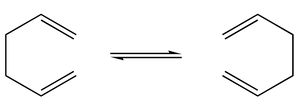
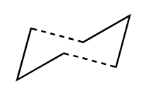
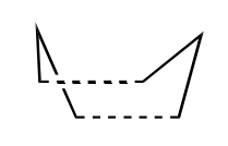
This [3,3]-sigmatropic shift rearrangement has been the subject of numerous experimental and computational studies (e.g. Houk et al. DOI:10.1021/ja00101a078 ), and for a long time its mechanism (concerted, stepwise or dissociative) was the subject of some controversy. Nowadays it is generally accepted that the reaction occurs in a concerted fashion via either a "chair" or a "boat" transition structure, with the "boat" transition structure lying several kcal/mol higher in energy. The B3LYP/6-31G* level of theory has been shown to give activation energies and enthalpies in remarkably good agreement with experiment. In this tutorial we will show how these can be calculated using Gaussian.
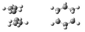
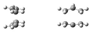
| Chair Transition State | Boat Transition State |
Optimizing the Reactants and Products
In this section you will learn how to optimize a structure, symmetrize it to find its point group, calculate and visualize vibrational frequencies and correct potential energies in order to compare them with experimental values. It is assumed that you are already familiar with using the builder in GaussView.
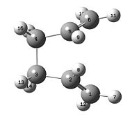
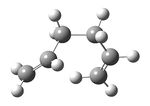
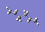
(a) Using GaussView, draw a molecule of 1,5-hexadiene with an "anti" linkage (aproximately a.p.p conformation) for the central four C atoms . Clean the structure using the Clean function under the Edit menu.
Now we will optimize the structure at the HF/3-21G level of theory. Select Gaussian under the Calculate menu, click on the Job Type tab and choose Optimization. The default method should already be Hartree Fock and the default basis set is 3-21G, so there should be no need to change these. You can check this by clicking on the Method tab. Change the %mem under the Link 0 tab to 250 MB (though this could be increased to 500 MB). Submit the job by clicking on the Submit button at the bottom of the window and give the job a meaningful name (e.g. react_anti).
When the job has finished, you will be asked if you want to open a file. Select Yes and choose the checkpoint (chk) file with the name of the job you have just run (e.g. react_anti.chk). This checkpoint file is a binary file that stores data calculated by Gaussian. The name of the chk file should have been assigned by default, but by default, this file will be created in the C:\Windows\G03\Scratch folder. Once the file has been opened, click on the Summary button under the Results menu and make a note of the energy.
Does your final structure have symmetry? Select Symmetrize under the Edit menu (note that sometimes it is necessary to relax the search criteria under the Point Group menu). Make a note of the point group.
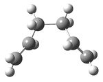
(b) Now draw another molecule of 1,5-hexadiene with a "gauche" linkage for the central four C atoms. Would you expect this structure to have a lower or a higher energy than the anti structure you have just optimized? Optimize the structure at the HF/3-21G level of theory and compare your final energy with that obtained in (a). Again, check if the molecule has symmetry and make a note of the point group.
(c) Normally, calculated activation energies and enthalpies use the lowest energy conformation of a reactant molecule as a reference. Based on your results from above, try to predict what the lowest energy conformation of 1,5-hexadiene might be. Test out your hypothesis by drawing the structure and optimizing it.
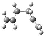
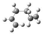
(d) A table containing the low energy conformers of 1,5-hexadiene and their point groups is shown in Appendix 1. Compare the structures that you have optimized with those in the table and see if you can identify your structure.
(e) Draw the Ci anti2 conformation of 1,5-hexadiene (unless you have already located it). Optimize it at the HF/3-21G level of theory and make sure it has Ci symmetry. Compare your final energy to the one given in the table.
(f) When you are happy that your structure is the same as the one in the table, reoptimize it at the B3LYP/6-31G* level (6-31G* is equivalent to 6-31G(d) by selecting DFT under the Method menu and B3LYP from the box with the functionals on the right-hand side. Now select Link 0 and change the name of the chk file to the name of the DFT optimization that you are about to run. Note that it is always advisable to do this when re-using or modifying existing structures to ensure that the original chk file is not overwritten. Run the job and make a note of the energy. Now compare the final structures from the HF/3-21G calculation with that at the higher level of theory. How much does the overall geometry change?
(g) The final energies given in the output file represent the energy of the molecule on the bare potential energy surface. To be able to compare these energies with experimentally measured quantities, they need to include some additional terms, which requires a frequency calculation to be carried out. The frequency calculation can also be used to characterize the critical point, i.e. to confirm that it is a minimum in this case: that all vibrational frequencies are real and positive.
Starting from your optimized B3LYP/6-31G* structure, run a frequency calculation at the same level of theory. You can do this by selecting Frequency under the Job Type tab. Ensure that the method is still correctly specified under the Method tab (caution: on Windows, sometimes 'scrf=(solvent=water,check)' is incorrectly added!) and then change the name of the chk file under the Link 0 tab to the name of the frequency job that you are about to run. Run the job. Once the job has finished, open the log file this time. Select Vibrations under the Results menu. A list of all the vibrational frequencies modes should appear. Check that there are no imaginary frequencies, only real ones. You can visualize some of these vibrations under this menu and simulate the infrared spectrum.
Now, select View File under the Results menu and open the output file in the visualizer. Scroll down to the section beginning Thermochemistry. Under the vibrational temperatures a list of energies should be printed. Make a note of (i) the sum of electronic and zero-point energies, (ii) the sum of electronic and thermal energies, (iii) the sum of electronic and thermal enthalpies, and (iv) the sum of electronic and thermal free energies. The first of these is the potential energy at 0 K including the zero-point vibrational energy (E = Eelec + ZPE), the second is the energy at 298.15 K and 1 atm of pressure which includes contributions from the translational, rotational, and vibrational energy modes at this temperature (E = E + Evib + Erot + Etrans), the third contains an additional correction for RT (H = E + RT) which is particularly important when looking at dissociation reactions, and the last includes the entropic contribution to the free energy (G = H - TS). It is important to make sure that you select the correct energy/enthalpy term to compare to your experimental values. Note that these corrections can also be calculated at other temperatures using the Temperature option in Gaussian, If you have time, try re-calculate these quantities at 0 K as shown in the Advanced GaussView Tutorial.
Optimizing the "Chair" and "Boat" Transition Structures
In this section you will learn how to set up a transition structure optimization (i) by computing the force constants at the beginning of the calculation, (ii) using the redundant coordinate editor, and (iii) using QST2. You will also visualize the reaction coordinate and run the IRC (Intrinisic Reaction Coordinate) and calculate the activation energies for the Cope rearrangement via the "chair" and "boat" transition structures.
The "chair" and "boat" transition structures for the Cope rearrangement are shown in Appendix 2. Both consist of two C3H5 allyl fragments positioned approximately 2.2 Å apart, one with C2h symmetry and the other with C2v symmetry.
(a) Draw an allyl fragment (CH2CHCH2) and optimize it using the HF/3-21G level of theory. Your structure should look like one half of the transition structures shown below.
Now open a new GaussView window by going to the File menu and selecting New and then Create MolGroup. Copy the optimized allyl structure from the first calculation by selecting Copy under the Edit menu, and then paste it twice into the new window by selecting Paste and then Append Molecule. Now orient the two fragments so that they look roughly like the chair transition state below by using the Shift Alt keys + Left Mouse button to translate one fragment with respect to the other and the Alt key + Left Mouse button to rotate it. The distance between the terminal ends of the allyl fragments should be approximately 2.2 Å apart. Save this structure to a Gaussian input file with a meaningful name (e.g. chair_ts_guess).
We are now going to optimize this transition state manually in two different ways. Transition state optimizations are more difficult than minimizations because the calculation needs to know where the negative direction of curvature (i.e. the reaction coordinate) is. If you have a reasonable guess for your transition structure geometry, then normally the easiest way to produce this information is to compute the force constant matrix (also known as the Hessian) in the first step of the optimization which will then be updated as the optimization proceeds. This is what we will try to do in the next section. However, if the guess structure for the transition structure is far from the exact structure, then this approach may not work as the curvature of the surface may be significantly different at points far removed from the transition structure. In some cases, a better transition structure can be generated by freezing the reaction coordinate (using Opt=ModRedundant and minimizing the rest of the molecule. Once the molecule is fully relaxed, the reaction coordinate can then be unfrozen and the transition state optimization is started again. One advantage of doing this, is that it may not be necessary to compute the whole Hessian once this has been done, and just differentiating along the reaction coordinate might give a good enough guess for the initial force constant matrix. This can save a considerable amount of time in cases where the force constant calculation is expensive.
(b) Use Hartree Fock and the default basis set 3-21G for parts (b) to (f).
Create a new MolGroup (File → New → Create MolGroup) and copy and paste your guess structure into the window. Now set up a Gaussian optimization for a transition state. Go to the Gaussian menu under Calculate and click on the Job Type tab. Select Opt+Freq and then change Optimization to a Minimum to Optimization to a TS (Berny). Choose to calculate the force constants Once and in the Additional keyword box at the bottom, type Opt=NoEigen. The latter stops the calculation crashing if more than one imaginary frequency is detected during the optimization which can often happen if the guess transition structure is not good enough. Submit the job. If the job completes successfully, you should have optimized to the structure shown in Appendix 2 and the frequency calculation should give an imaginary frequency of magnitude 818 cm-1. Animate the vibration and ensure that it is the one corresponding to the Cope rearrangement.
(c) Now we will try optimizing the transition structure again using the frozen coordinate method. Create a new MolGroup (File → New → Create MolGroup) and copy and paste your guess structure into the window again. Now select Redundant Coord Editor from the Edit menu. Click on the highlighted file icon at the top left-hand corner (Create a New Coordinate) and a line should appear below saying Add Unidentified (?, ?, ?, ?). Now go back to the GaussView window and select two of the terminal carbons from the allyl fragments which form/break a bond during the rearrangement. Return to the coordinate editor and select Bond instead of Unidentified and select Freeze Coordinate instead of Add. Now click on the icon again to generate another coordinate. This time select the opposite two terminal atoms and again select Bond and Freeze Coordinate. Click OK. Now set up the optimization as if it were a minimum and you should see the option Opt=ModRedundant already included in the input line. Submit the job.
Note: GaussView allows you to produce an input file with the frozen coordinate specified as e.g. B 5 1 2.200000 F. Unfortunately, a recent update to the Gaussian program means it does not recognise this syntax, and just ignores this line. This means that the coordinate ends up being optimised rather than frozen. Therefore do not use this method, but ensure the guess structure has suitable guess transition bond distances(~2.2 Å) using the Modify Bond tool in GaussView --Rzepa 14:39, 29 October 2012 (UTC)
(d) When the job has finished, open the chk file. You should find that the optimized structure looks a lot like the transition you optimized in section (b), except the bond forming/breaking distances are fixed to 2.2 Å. Now we are going to optimize them too. Open the Redundant Coord Editor from the Edit menu again and create a new coordinate as before by clicking on the icon, Select one of the bonds that was previously frozen and this time choose Bond instead of Unidentified and Derivative instead of Add. Repeat the procedure for the other bond. This time you need to set up a transition state optimization but we are not going to calculate the force constants as we did in section (b) (so we leave this option as Never), instead we will use a normal guess Hessian modified to include the information about the two coordinates we are differentiating along. Change the name of the chk file in Link 0 if you do not want to write over the previous calculation and submit the job. When the calculation has finished, open the chk file, check the bond forming/bond breaking bond lengths and compare the structure to the one you optimized in section (b).
(e) Now we will optimize the boat transition structure. We will do this using the QST2 method. In this method, you can specify the reactants and products for a reaction and the calculation will interpolate between the two structures to try to find the transition state between them. You must make sure that your reactants and products are numbered in the same way. Therefore, although our reactants and products are both 1,5-hexadiene, we will need to manually change the numbering for the product molecule so that it corresponds to the numbering obtained if our reactant had rearranged.
e.g.

Open the chk file corresponding to the optimized Ci reactant molecule (anti2 in Appendix 1). Now open a second window and create a new MolGroup. Copy the optimized reactant molecule into the new window. In the same window, now select File → New → Add to MolGroup. The original molecule should disappear and a green circle should appear at the top left-hand corner with a 2 next to it. Clicking on the down arrow by the 2 will take you back to the original window and you will see your molecule again. This is how we read multiple geometries into GaussView. Go back to window 2, and copy and paste the reactant molecule a second time. This is going to be the product molecule and will be the molecule on which we need to change the numbering. If you now click on the icon showing two molecules side by side, then you can view both molecules simultaneously.
Now go to the View menu and select Labels so that you can see the numbering on both structures. Orient the two structures separately so they look something like the following:
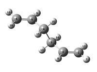
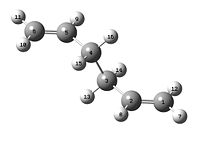
| Reactant | Product |
Now click on the product structure. Go to the Edit menu and select Atom List. Starting from Atom 1 on the reactant, go through and renumber all the atoms on the Product so that they match the reactant molecule, e.g. for the numbering above you would start by changing atom 6 on the product molecule to atom 1. The other atom numbers will update as you do this so make sure you do it in the correct order. At the end, the numbering on your two molecules should correspond to each other in the following way:
| Reactant | Product |
Now we will set up the first QST2 calculation. Go to the Gaussian menu and select Job Type as Opt+Freq, and optimize to a transition state. This time you will have two options - TS (Berny) which we used in the previous calculations and TS (QST2). Select TS (QST2). Submit the job.
You will find that the job fails. To see why, open the chk file you created and view the structure. You will see that it looks a bit like the chair transition structure but more dissociated. In fact when the calculation linearly interpolated between the two structures, it simply translated the top allyl fragment and did not even consider the possibility of a rotation around the central bonds. It is clear that the QST2 method is never going to locate the boat transition structure if we start from these reactant and product structures.
Now go back to the original input file where you set up your QST2 calculation. We will now modify the reactant and product geometries so that they are closer to the boat transition structure. Click on the reactant molecule first and select the central C-C-C-C dihedral angle (i.e. C2-C3-C4-C5 for the molecule above) and change the angle to 0o. Then select the inside C-C-C (i.e. C2-C3-C4 and C3-C4-C5 for the molecule above) and reduce them to 100o. Do the same for the product molecule. Your reactant and product molecules should now look like the following:
| Reactant | Product |
Set up the QST2 calculation again, renaming both the chk file under Link 0 and the input file. Run the job again. This time it should converge to the boat transition structure. Check that there is only one imaginary frequency and visualize its motion.
The object of this exercise is to illustrate that although the QST2 method is has some advantages because it is fully automated, it can often fail if your reactants and products are not close to the transition structure. There is another method, the QST3 method, that allows you to input the geometry of a guess transition structure also and this can often be more reliable. If you have time, you can try generating a guess boat transition structure and see if you can get the calculation to converge using the original reactant and product molecules. Remember to check the atom numbers in the transition structure are in the right order.
(f) Take a look at your optimized chair and boat transition structures. Which conformers of 1,5-hexadiene do you think they connect? You will find that it is almost impossible to predict which conformer the reaction paths from the transitions structures will lead to. However, there is a method implemented in Gaussian which allows you to follow the minimum energy path from a transition structure down to its local minimum on a potential energy surface. This is called the Intrinsic Reaction Coordinate or IRC method. This creates a series of points by taking small geometry steps in the direction where the gradient or slope of the energy surface is steepest.
Open the chk file for one of your optimized chair transition structures. Under the Gaussian menu, select IRC under the Job Type tab. You will be presented with a number of options. The first is to decide whether to compute the reaction coordinate in one or both directions. As our reaction coordinate is symmetrical, we will only choose to compute it in the forward direction. Normally you would do both forward and reverse, either in one job or in two separate jobs. You are also given the option to calculate the force constants once, at every step along the IRC or to read them from the chk file. You would use the latter option if you have previously run a frequency calculation. In this case, to avoid confusion with chk files, we will just recompute them at the beginning of the calculation. (The IRCMax option can also be specified here. This takes a transition structure as its input, and finds the maximum energy along a specified reaction path, taking into account zero-point energy etc., and produces all the quantities needed for a variational transition state theory calculation. We will leave this unchecked for the purposes of this exercise.) The final option to consider is the number of points along the IRC. The default is 6 but this is normally never enough. Let's change this to 50 and see how the calculation progresses. Change the name of the chk file under Link 0 and submit the job. The job will take a while so now is a good time to take a coffee break...
When the IRC calculation has finished, open the chk file with all the intermediate geometries and see how the calculation has progressed. You will find that it hasn't reached a minimum geometry yet. This leaves you three options: (i) you can take the last point on the IRC and run a normal minimization; (ii) you can restart the IRC and specify a larger number of points until it reaches a minimum; (iii) you can redo the IRC specifying that you want to compute the force constants at every step. There are advantages and disadvantages to each of these approaches. Approach (i) is the fastest, but if you are not close enough to a local minimum, you may end up in the wrong minimum. Approach (ii) is more reliable but if too many points are needed, then you can also veer off in the wrong direction after a while and end up at the wrong structure. Approach (iii) is the most reliable but also the most expensive and is not always feasible for large systems. You can try any or all of these approaches and see which conformation you end up in.
(g) Finally we need to calculate the activation energies for our reaction via both transition structures. To do this we will need to reoptimize the chair and boat transition structures using the B3LYP/6-31G* level of theory and to carry out frequency calculations. You can start from the HF/3-21G optimized structures. Once the calculations have converged, compare both the geometries and the difference in energies between the reactants and transition states at the two levels of theory. What you should find is that the geometries are reasonably similar, but the energy differences are markedly different. As a consequence of this, it is often more computational efficient to map the potential energy surface using the low level of theory first and then to reoptimize at the higher level as we have done in this exercise.
The experimental activation energies are 33.5 ± 0.5 kcal/mol via the chair transition structure and 44.7 ± 2.0 kcal/mol via the boat transition structure at 0 K. If you take the values computed at 0 K, how close are they to the experimental values? You can also find the energies with thermal correction at 298.15 K under the Thermochemistry data in the output file. If you have time, you can recompute them at higher temperature. Alternatively, you can use the utility program FreqChk to obtain energies at a different temperature. This only requires the chk file from a frequency calculation and allows you to retrieve frequency and thermochemistry data as well as calculating them with an alternate temperature, pressure, scale factor, and/or isotope substitutions. The FreqChk utility program can be accessed from Gaussian03W. Launch Gaussian03W. Select utilities from the menu and click on FreqChk to launch the utility program. You will be prompted for a chk file. Select your chk file from the C:\G03W\Scratch directory and follow the instructions from this web link to proceed.
Appendix 1
| Conformer | Structure | Point Group | Energy/Hartrees HF/3-21G |
Relative Energy/kcal/mol |
| gauche1 | C2 | -231.68772 | 3.10 | |
| gauche2 | C2 | -231.69167 | 0.62 | |
| gauche3 | C1 | -231.69266 | 0.00 | |
| gauche4 | C2 | -231.69153 | 0.71 | |
| gauche5 | C1 | -231.68962 | 1.91 | |
| gauche6 | C1 | -231.68916 | 2.20 | |
| anti1 | C2 | -231.69260 | 0.04 | |
| anti2 | Ci | -231.69254 | 0.08 | |
| anti3 | C2h | -231.68907 | 2.25 | |
| anti4 | C1 | -231.69097 | 1.06 |
Appendix 2
| C2h Chair Transition State |
| C2v Boat Transition State |
Results Table
Summary of energies (in hartree)
| HF/3-21G | B3LYP/6-31G* | |||||
|---|---|---|---|---|---|---|
| Electronic energy | Sum of electronic and zero-point energies | Sum of electronic and thermal energies | Electronic energy | Sum of electronic and zero-point energies | Sum of electronic and thermal energies | |
| at 0 K | at 298.15 K | at 0 K | at 298.15 K | |||
| Chair TS | -231.619322 | -231.466705 | -231.461346 | -234.556983 | -234.414919 | -234.408998 |
| Boat TS | -231.602802 | -231.450929 | -231.445300 | -234.543093 | -234.402340 | -234.396006 |
| Reactant (anti2) | -231.692535 | -231.539539 | -231.532566 | -234.611710 | -234.469203 | -234.461856 |
*1 hartree = 627.509 kcal/mol
Summary of activation energies (in kcal/mol)
| HF/3-21G | HF/3-21G | B3LYP/6-31G* | B3LYP/6-31G* | Expt. | |
| at 0 K | at 298.15 K | at 0 K | at 298.15 K | at 0 K | |
| ΔE (Chair) | 45.70 | 44.69 | 34.06 | 33.17 | 33.5 ± 0.5 |
| ΔE (Boat) | 55.60 | 54.76 | 41.96 | 41.32 | 44.7 ± 2.0 |
The Diels Alder Cycloaddition
In this exercise, you will characterise transition structures using any of the methods described above in the tutorial: the choice is up to you. In addition, you will look at the shape of some of the molecular orbitals. To help you structure your report, there is a data/discussion sheet at the end of this section.
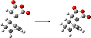
The Diels Alder reaction belongs to a class of reactions known as pericyclic reactions. The π orbitals of the dieneophile are used to form new σ bonds with the π orbitals of the diene. Whether or not the reactions occur in a concerted stereospecific fashion (allowed) or not (forbidden) depends on the number of π electrons involved. In general the HOMO/LUMO of one fragment interacts with the HOMO/LUMO of the other reactant to form two new bonding and anti-bonding MOs. The nodal properties allow one to make predictions according to the following rule:
If the HOMO of one reactant can interact with the LUMO of the other reactant then the reaction is allowed.
The HOMO-LUMO can only interact when there is a significant overlap density. If the orbitals have different symmetry properties then no overlap density is possible and the reaction is forbidden.
If the dieneophile is substituted, with substituents that have π orbitals that can interact with the new double bond that is being formed in the product, then this interaction can stabilise the regiochemistry (i.e. head to tail versus tail to head) of the reaction. In this exercise you will study the nature of the transition structure for the Diels Alder reaction, both for the prototypical reaction and for the case where both diene and dieneophile carry substituents, and where secondary orbital effects are possible. Clearly, the factors that control the nature of the transition state are quantum mechanical in origin and thus we shall use methods based upon quantum chemistry.
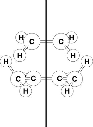
Shown on the right is a diagram of the transition state for the Diels-Alder reaction between ethylene and butadiene. The ethylene approaches the cis form of butadiene from above.
Before beginning our quantitative study, it is helpful to discuss the interaction of the π orbitals in a simple qualitative way.
You will confirm some of these considerations in your computations.
The principal orbital interactions involve the π/ π* orbitals of ethylene and the HOMO/LUMO of butadiene. It is referred to as [4s + 2s] since one has 4 π orbitals in the π system of butadiene. The orbitals of ethylene and butadiene and ethylene can be classified as symmetric s or anti-symmetric a with respect to the plane of symmetry shown.
The HOMO of ethylene and the LUMO of butadiene are both s (symmetric with respect to the reflection plane) and the LUMO of ethylene and the HOMO of butadiene are both a. Thus it is the HOMO-LUMO pairs of orbital that interact, and energetically, the HOMO of the resulting adduct with two new σ bonds is a.
Exercise
Use the the AM1 semi-empirical molecular orbital method for these calculations (to start with).
i) Use GaussView to build cis butadiene, and optimize the geometry using Gaussian. Plot the HOMO and LUMO of cis butadiene and determine its symmetry (symmetric or anti-symmetric) with respect to plane.
There are two ways to do this in GaussView. One is: Select Edit→MOs. Select the HOMO and the LUMO from the MO list (highlights it yellow). Click the button Visualise (not Calculation), then Update. Alternately, having calculated the surface for this orbital, you can display it in the main GaussView window for the molecule, from the Results→Surfaces menu. Select Surface Actions→Show Surface. Having displayed the surface this way, you can also select View→Display Format→Surface, and change Solid to Mesh.
ii) Computation of the Transition State geometry for the prototype reaction and an examination of the nature of the reaction path.

The transition structure has an envelope type structure, which maximizes the overlap between the ethylene π orbitals and the π system of butadiene. One way to obtain the starting geometry is to build the bicyclo system (b) and then remove the -CH2-CH2- fragment. One must then guess the interfragment distance (dashed lines) and optimize the structure, but use any method you wish, based on the tutorial above, to characterise the transition structure. Confirm you have obtained a transition structure for the Diels Alder reaction!
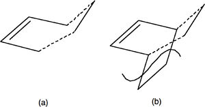
Once you have obtained the correct structure, plot the HOMO as in (i). Rotate the molecule so that the symmetry and nodal properties of the system can be interpreted, and save a copy of the image.
(iii) To Study the regioselectivity of the Diels Alder Reaction
Cyclohexa-1,3-diene 1 undergoes facile reaction with maleic anhydride 2 to give primarily the endo adduct. The reaction is supposed to be kinetically controlled so that the exo transition state should be higher in energy.
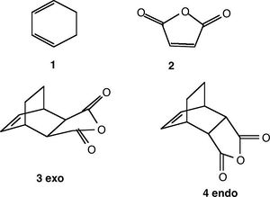
Locate the transition structures for both 3 and 4. Compare the energies of the endo and exo forms.
Measure the bond lengths of the partly formed σ C-C bonds and the other C-C distances. Make a sketch with the important bond lengths. Measure the orientation, (C-C through space distances between the -(C=O)-O-(C=O)- fragment of the maleic anhydride and the C atoms of the “opposite” -CH2-CH2- for the exo and the “opposite” -CH=CH- for the endo). The structure must be a compromise between steric repulsions of the -CH2-CH2- fragment and the maleic anhydride for the exo versus secondary orbital interactions between the π systems of -CH=CH- and -(C=O)-O-(C=O)- fragment for the endo.
Plot the HOMO as in the previous exercise. Examine carefully the nodal properties of the HOMO between the -(C=O)-O-(C=O)- fragment and the remainder of the system. What can you conclude about the so called “secondary orbital overlap effect”?
Suggested Discussion
Use this template as a guide. Screen images can be saved from the GaussView File menu.
For cis butadiene:
Plot the HOMO and LUMO and determine the symmetry (symmetric or anti-symmetric) with respect to the plane.
For the ethylene+cis butadiene transition structure:
Sketch HOMO and LUMO, labeling each as symmetric or anti symmetric.
Show the geometry of the transition structure, including the bond-lengths of the partly formed σ C-C bonds.
What are typical sp3 and sp2 C-C bondlengths? What is the van der Waals radius of the C atom? What can you conclude about the C-C bondlength of the partly formed σ C-C bonds in the TS.
Illustrate the vibration that corresponds to the reaction path at the transition state. Is the formation of the two bonds synchronous or asynchronous? How does this compare with the lowest positive frequency?
Is the HOMO at the transition structure s or a?
Which MOs of butadiene and ethylene have been used to form this MO? Explain why the reaction is allowed.
For the cyclohexa-1,3-diene reaction with maleic anhydride:
Give the relative energies of the exo and endo transition structures.
Comment on the structural difference between the endo and exo form. Why do you think that the exo form could be more strained?
Examine carefully the nodal properties of the HOMO between the -(C=O)-O-(C=O)- fragment and the remainder of the system. What can you conclude about the so called “secondary orbital overlap effect”?
(There is some discussion of this in Ian Fleming's book 'Frontier Orbitals and Organic Chemical Reactions').
Further discussion:
What effects have been neglected in these calculations of Diels Alder transition states?
Look at published examples and investigate further if you have time. (e.g. DOI:10.1021/jo0348827 )
See also: Timetable,Intro lecture, Programs, Module 1, Module 2, Module 3
© 2008-2011, Imperial College London

