TransitionMetalCoordination
Transition Metal Coordination
Note: the contents of this course are directly taken from Dr. George Britovsek's notes (2011-2012) and are copyright of Imperial College London.
Introduction
This course aims to provide you with the ability to identify and/or anticipate many properties of a transition metal complex, including likely geometry, electronic configuration, possible sources of colour and magnetism and whether it is likely to be labile or inert.
The Crystal Field Approximation
Many of the spectroscopic and magnetic properties of transition metal complexes may be rationalised by considering the effect on the relative energies of the d-orbitals when 6-point charges are placed around the metal centre. This is a reasonable first approximation because ligands are electron pair donors and accordingly from the metal's 'point of view' are areas of localized electron density. The wave functions for atomic orbitals are derived assuming a perfectly spherically symmetric (or 'isotropic') electric environment (i.e., 'Free space'). In this situation the orbitals are all of the same energy, i.e., degenerate. When ligands, or in the present situation localized negative charges, are brought up to the metal the relative energies of these metal orbitals charge according to the symmetry of the ligand arrangement. For the simplest case, the octahedron (Oh symmetry), the orbitals split into two sets. The greater the negative charge (or the more basic the ligand) the greater the splitting.
The degeneracy of a set of orbitals is denoted by the symbols:
- a (one orbital),
- e (two orbitals),
- t (three orbitals).
Octahedral Complexes
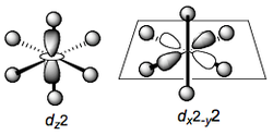
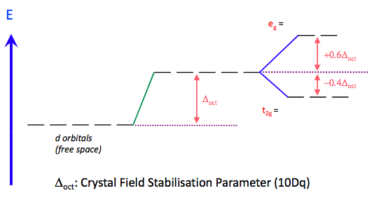
The orbitals dxy, dxz and dyz (i.e. those which have cross-terms in the subscripts)have their lobes lying off the metal-ligand axes x, y, and z. Accordingly, these interact much less with the negative charges. Relative to the average energy of all the d orbitals, these are stabilized. These three form a set of energetically degenerate orbitals. d-orbitals in an octahedral environment have gerade symmetry, and so we denote this set of orbitals t2g
The remaining two orbitals dx2-y2 and dz2 have their lobes pointing directly along the metal-ligand axes and accordingly interact very strongly, and unfavorably with the point charges. These two orbitals are destabilised to the same extent by this interaction and form a doubly degenerate set (e) of gerade symmetry denoted eg.
The crystal field splitting of the d-orbitals in an octahedral complex is given below:
The energy difference between the t2g and eg orbitals is denoted Δo (o for octahedral) and is a function of the 'field strength' of the ligand, i.e. how good an electron donor it is. Thus for example NH3, which is a stronger base than water, when complexed to a metal causes a larger splitting (Δo). It is possible to construct an empirical order of common ligands according to their ability to split the energies of these two sets of orbitals. This qualitative ordering of ligands is known as the spectrochemical series:
This series is empirical, i.e., derived from experimental results (UV-vis spectroscopy) and there are some notable inconsistencies with respect to the Crystal Field Approximation, which is based purely on the assumption that ligands act as point charges. This would mean that all anionic ligands should therefore be substantially stronger ligands than neutral ones. Why is (neutral) water a ‘stronger’ ligand than (anionic) hydroxide? If the charge density of the ligand is the most important factor why should (monoatomic) F- be such a weaker ligand than CN- or NCS- (negative charge spread over 2 or 3 atoms)?
Square Planar Complexes
Whilst the octahedral geometry is common for transition metal complexes, there are many four-coordinate complexes, which adopt either a square planar (D4h) structure or a tetrahedral (Td) geometry. To understand why this is so, we must work through the same arguments used above but applied to these two geometries.
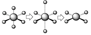
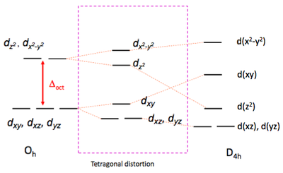
The square planar orbital splitting diagram is most easily derive by beginning with that derived for Oh symmetry. We must consider what happens to the energy of the respective orbitals if we remove two trans ligands along the z-axis. The orbital which is most strongly affected is dz2 which points towards these departing ligands. The removal of negative charge from the vicinity of this orbital strongly stabilises it. This is in fact true for any orbital which has a z component, i.e., dxz and dyz. Since these do not point directly, to where the ligands were, the stabilisation is not as great as that for dz2 . To keep the average d-orbital energy the same, the remaining orbitals dxy and dx2-y2 are raised in energy, due in part to contraction of the 4 M-L bonds as the axial ligands depart. This leads to a splitting of the two sets of orbitals into four distinct energy levels.
Of particular note is the high energy of the dx2-y2 level. This is so substantial that it is normally not occupied, i.e., the square planar geometry is strongly disfavored for d10 electronic configurations. On the other hand, it is extremely common for d8 four-coordinate complexes, so long as the ligands are not so bulky as to force the complex into a tetrahedral geometry.
Tetrahedral Complexes
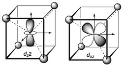
The tetrahedral case is somewhat more difficult to visualise. Assume that the metal is at the centre of a cube with ligands (point charges) at four of the eight vertices. Note: Both tetrahedral and octahedral symmetry are considered as subsets of ‘cubic’ symmetry as they arise from the symmetric placement of 6 or 4 ligands on the faces or (half the) vertices of a cube. The axes are defined such that they pass through the sides of the cube perpendicular to the faces. Given this coordinate frame we see that the eg orbitals now have their lobes between the ligands and are accordingly stabilized relative to the average d orbital energy.
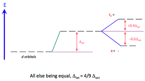
The t2g orbitals on the other hand point in the direction of the ligands and are therefore destabilised (relatively). We therefore have the opposite splitting to the Oh case. We must drop the '‘g’' superscript because there is no centre of inversion (‘i’) for a tetrahedron. Because there are only four ligands the splitting is less than for an octahedron (6 ligands) and is approximately 4/9 of the magnitude for an octahedral arrangement [approximately because we must assume the same metal-ligand bond length for both cases, which may not be the case]. The interactions are illustrated for the dz2 and dxz cases but you should confirm this for the other degenerate orbitals. The energetic splitting of the orbitals is denoted Δt and the displacements from the average d-orbital energy are once again 0.4Δt for t2 and 0.6Δt for e.
Factors Affecting the Magnitude of "Δ"
The Nature of the Ligand
The Crystal Field model describes ligands as negative charges. Clearly, some ligands are more ‘negative’ than others. It should be possible to a priori arrange ligands according to some quantity, e.g. ionisation potential, basicity etc and this should parallel the trend in values of Δ for related complexes. Empirically the spectrochemical series does this, but there is unfortunately little correlation with any such single property of the free ligand.
The Nature of the Metal
OXIDATION STATE
As the formal positive charge on the metal increases (and ligands are drawn closer electrostatically) any electrostatically derived effect should increase. This is observed:
| Complex | Metal Oxidation State | Δo (cm-1) | Complex | Metal Oxidation State | Δo (cm-1) |
|---|---|---|---|---|---|
| [CrF6]3- | +3 | 15,060 | [CrF6]2- | +4 | 22,000 |
| [Fe(CN)6]4- | +2 | 32,200 | [Fe(CN)6]3- | +3 | 35,000 |
| [Ru(OH2)6]2+ | +2 | 19,800 | [Ru(OH2)6]3+ | +3 | 28,600 |
On descending a triad, the values of Δo for a series of analogous complexes increasees substantially.
| Complex | Metal Oxidation State | Δo (cm-1) | Complex | Metal Oxidation State | Δo (cm-1) |
|---|---|---|---|---|---|
| [MnF6]2- | +4 | 21,860 | [Co(NH3)6]3+ | +3 | 22,870 |
| [TcF6]2- | +4 | 28,400 | [Rh(NH3)6]3+ | +3 | 34,100 |
| [ReF6]2- | +4 | 32,800 | [Ir(NH3)6]3+ | +3 | 41,200 |
For this reason, high spin configurations are much less common for 4d and 5d metal complexes,
e.g., of the complexes [M(OH2)6]2+ (M = Fe, Ru, Os) it is only the iron complex which is high spin (see below).
GEOMETRY
We have already seen that the splitting produced by 4 ligands in a tetrahedron is ca. 4/9 that produced by six octahedrally coordinated ligands.
Thus low spin tetrahedral complexes are exceedingly rare.
| Complex | Metal Oxidation State | Δo (cm-1) |
|---|---|---|
| [VCl4] | +4 | 7,900 |
| [VCl6]2- | +4 | 15,400 |
Crystal Field Stabilising Energy and Pairing Energy
With the orbital splittings for Oh, D4h and Td electric fields in hand we can now start to consider the energetics of complexes as a result of the d-configuration.
The term used commonly is crystal field stabilisation energy (C.F.S.E.). This is a comparison of the total energy of the d-electrons relative to their being
in 5 degenerate orbitals at the energetic baricentre (i.e., within and isotropic field).
Crystal Field Stabilisation Energy
The d1, d2 and d3 cases are straight-forward. Hund requires that the electrons in d2 and d3 cases will go into different t2g orbitals with parallel spins.
The CFSE is therefore 0.4 Δo, 0.8 Δo and 1.2 Δo respectively:
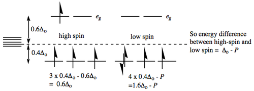
The d4 case brings some complications in that if Δo is not very large, e.g. weak ligands in the spectrochemical series, we have the choice of putting the 4th electron into t2g or eg orbitals. Specifically, a quantity known as the Pairing Energy 'P' refers to the energy required to pair up two electrons in the same orbital (see below). If P > Δo then the electron will go into the higher orbital (referred to as high spin). If however, P < Δo then the electron will go into the lower orbital (referred to as low spin):
Different text books use different conventions (+ or -) for Δo and P. Since you will encounter both, it is important to remember the 'sense' of the energies, i.e., the pairing energy has to be put into the system; electrons below the barycentre represent a stabilisation, whilst electrons in orbitals above the baricentre represent a relative energy expenditure.
Note: for the picture above remember that each electron pairing entails the input of pairing energy,
so the final energy requires the subtraction of however much pairing energy was input.
What is Pairing Energy?
The pairing energy has two primary and approximately additive origins. Firstly there will be a Coulombic repulsion as a result of trying to place two electrons in the same orbital. This naturally decreases for 3d > 4d > 5d due to the more diffuse nature of the orbitals. Secondly, there is a loss of exchange energy (Hund's rule). Exchange energy refers to the interaction of an electron with any other (unpaired) electron with a parallel spin. This is proportional to the number of such interactions within a set of orbitals. Within a set of 5 d-orbitals the possible "exchanges" are shown below and this is illustrated for the d5 case. This large contribution for d5, partly explains why many d5 complexes are high-spin: Forcing electrons to pair will lead to the greatest loss of exchange energy.
Pairing energies are calculated from the spectroscopic properties of the free ion and are thought to be 15-30% higher than is actually observed in complexes.
This is a result of the nephelauxetic (= cloud expansion) effect. This is the name given to rationalize a collection of phenomena which suggest that in complexes (c.f. the free ion), electrons appear to be not as mutually repulsive as might be expected. This is due to covalency (see later), i.e., the d-orbitals are diffused as a result of combination with ligand orbitals. By the orbitals being more spread out, the inter-electronic repulsion is reduced.
Some representative values of P for 3d metal ions follow (cm-1):
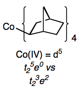
You are not expected to learn these (or any Δo values!). You should however be aware that they can be of the same approximate magnitude as typical values for Δo (which vary with ligands and are thus 'tunable'). Therefore situations may arise where the notional quantity Δo-P may in fact be quite small, and comparable to thermal energy available from the environment (ca. 200 cm-1). We will discuss this situation later when considering magnetism.
Note: also that since tetrahedral splittings are typically much smaller (Δt = 4/9Δo) than those for Oh complexes,
it is very rare to observe low-spin tetrahedral complexes. The first example was only confirmed in 1986.
How Well Does Crystal Field Theory Work?
Firstly we will consider some situations where the model is useful, then move on to situations which highlight its shortcomings.
There is a range of properties associated with the elements Sc, Ti, V --> Zn which, rather than following a smooth trend with increasing atomic number, forms a "two-humped plot". Generally, if crystal field effects are taken into account the ‘corrected’ curves are monotonous through the experimental values for d0, d5 and d10 cases.
This may be traced to a simple consideration of how CFSE (ignoring P) varies with d-configuration for weak field octahedral complexes.
Thus any property of a series of transition metal complexes which appears to provide a two-humped plot, with the effect being minimised (or maximised) for d1, d5 and d10 configurations probably arises from crystal field effects.
These properties include:
| Heats of Ligation | The heat released on taking the gaseous ion and placing it in an octahedral complex (derived from solution data in combination with appropriate energy cycles). |
| Ionic Radii | Taking the ionic radii of the chlorides and iodides of the divalent 3d metals, a smooth decrease would be expected as the successively added positive charges on the nucleus are less effectively screened by the added electrons. A smooth decrease is actually observed in the halides of the lanthanides (it is this incomplete screening of nuclear charge which results in 5d metals having approximately the same radii as 4d within a triad). |
| Lattice Energies | In situations where the metal ion is octahedrally coordinated in an ionic lattice, the lattice energies show the characteristic double hump. If CFSE corrections are included then the points lie on the smooth curve through Ca(II)-Mn(II)- Zn(II). |
| Stability Constants | Differences in free energy values follow from equilibrium constants (ΔG = -RTlnK ) and therefore differences in CFSE's may contribute to equilibrium constants. |
The Inadequacies of Crystal Field Theory
Not surprisingly, the crude assumption upon which CFT rests, that ligands are point charges without any covalent interactions, leads to numerous situations where the theory is inadequate. These involve situations where communication between the metal centre and the ligand can't be explained simply in electrostatic terms. Some well established examples follow:
(i) The positions of many ligands within the spectrochemical series is counter- intuitive based simply on the charge density of the ligand alone, e.g., hydroxide (anionic) is slightly lower in the series than neutral water. Fluoride is very low in the series and cyanide is very high. Both are anionic but the negative charge is spread over two atoms in the case of cyanide and so should appear less 'negative', i.e., lower than fluoride in series. Similarly many neutral ligands, e.g., CO, olefins, phosphines are high in the series, despite being neutral. These effects may be traced to "-interactions which are clearly beyond the scope of the CFT model.
(ii) In the inorganic NMR course you will meet numerous examples of couplings between metal and ligand nuclei, e.g., 1J(PtH) and 1J(PtP) in the complex [PtHCl(PPh3)2]. NMR
couplings are communicated through bonds involving orbitals with finite density at the centre of the nuclei, i.e., MO's comprising atomic s orbitals. Remember that p and d orbitals have nodes at the nucleus].
Molecular Orbital Approach to Crystal Field Theory
The above examples indicate that we now need a model, which accommodates covalency in the bonding, resulting in molecular orbitals which are spread over the entire molecule rather than isolated atomic orbitals. Electrons within these MO's will then be in communication (to varying extents) with all the atoms of the ligands. There are a variety of approaches to deriving the molecular orbitals for a complex, employing where appropriate, varying levels of sophistication. Some are more readily applicable to particular geometries (and thus geometrical preferences). Others give more accurate quantitative estimations of physical properties. Here we will consider the simplest description of an octahedral complex as an illustration of the basic principles. The approach is the same as for any molecule. We must first identify symmetry-allowed combinations of atomic and ligand orbitals (of comparable energy) which lead to effective non-zero overlap.
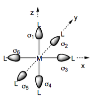
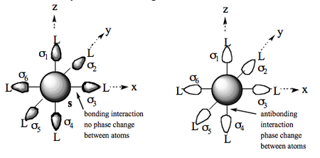
We begin by considering a set of six ligand orbitals about a metal centre, each of which has σ symmetry with respect to the M-L vector which we denote σ1, σ2 ... σ6.
We now consider possible combinations of these orbitals which may interact with the central metal orbitals. The simplest of these is the s orbital and a bonding molecular orbital. Along each metal-ligand vector there is no change in phase and so the orbital is M-L bonding in all directions. NB: In this discussion we will omit normalisation constants but be aware that they are necessary. Also the actual relative contributions of metal and ligand orbitals will depend on the nature of the metal and ligands. The antibonding version of this will have the reversed phases for the σn orbitals and be antibonding along each of the M-L vectors (phase change):
- BONDING = Ψ = s + σ1 + σ2 + σ3 ... + σ6
- ANTIBONDING = Ψ* = s - (σ1 + σ2 + σ3 ... + σ6).
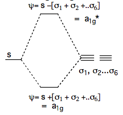
We will now dispense with the labels Ψ and Ψ* in favour of labels which are more informative. The number of orbitals of the same energy (degeneracy) will be denoted by a' (1), 'e' (2) and t' (3). The symmetry will be denoted by:
- g = gerade = [Ψ(x,y,z) = Ψ(-x,-y,-z)]
- u = ungerade = [Ψ(x,y,z) = -Ψ(x-,-y,-z)]
Ligand Interactions with p-Orbitals
We now consider a metal-based p-orbital (e.g., px) and see that only two of the ligand orbitals are of the correct symmetry for a net constructive overlap, i.e. σ3 and -(σ6). Note that:
- Firstly the symmetry of the central p-orbital (u) dictates the symmetry of the final MO.
- Secondly, there are three orbitals here of equal energy (the other two in the y and z directions) and so this is denoted t1u.
Ligand Interactions with d-Orbitals
We must consider the d-orbitals separately because they behave differently depending on whether or not the lobes point along the M-L vectors.
Firstly we note that because the dxy, dxz and dyz orbitals have π-symmetry with respect to the metal ligand vectors, there is no possible combination of σ1, σ2 ... σ6, which will be of correct symmetry to overlap constructively with these three d-orbitals. These orbitals are therefore 'non-bonding'. As a triply degenerate set they are denoted t and are of gerade symmetry, hence t2g.
The lobes of the dz2 and dx2-y2 orbitals (and the dz2 "collar") point along the M-L vectors and are of σ-symmetry and therefore, may overlap constructively to produce a degenerate set of bonding and antibonding orbitals:
Thus the combinations of the ligand σ-orbitals with the metal d-orbitals leads to the energy diagram:
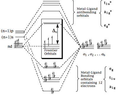
This MO diagram may be combined with those for the s and p orbitals to provide an overall molecular orbital scheme (below) which will contain 12 electrons from the ligands (6 electron pairs) and the total number of metal s and d electrons (illustrated for d3-ML6).
Key Points (Summary)
The important points to note from the final scheme are:
- The metal ligand bonding orbitals are filled by the 12 electrons from the ligand (this is consistent with the idea of a 'dative bond'). In subsequent discussions these are normally assumed and ignored.
- The remaining s and d electrons from the metal are fed into the 'Frontier Molecular Orbitals' which have the same pattern (and degeneracy) as derived from the Crystal Field approach. This is illustrated for a metal ion with 3 s+d electrons. Now the various double-hump phenomena which were previously explained by the CF model, also follow from the successive population of the t2g and eg* orbitals derived above.
- The molecular orbitals involved are now spread over the entire ML6 molecule and therefore we can explain why electronic communication between metal and ligand is apparent in spectroscopic phenomena.
π-Effects
Although the double-hump behaviour has now been rationalised, this treatment still leaves us without an adequate explanation of the orderings of ligands within the spectrochemical series. This may however be explained when the above approach is refined to include π-orbitals on the ligands. NB: The terms σ, π (and δ) refer to the symmetry properties of an orbital with respect to an axis lying on 0 (σ), 1 (π) or 2 (δ) nodal plans. Here we will be talking about the M-L axis. There is a variety of potential ligand orbitals which can have such π-symmetry . We need to consider two types of ligand π-orbitals.

π-Donor Orbitals
These are occupied ligand orbitals, e.g., halide, oxide, nitride, amide 'lone pairs' which are perpendicular to the M-L vector.
π-Acceptor (π-Acid) Orbitals
These are unoccupied ligand orbitals and include:
- Atomic d-Orbitals
Although halides are primarily viewed as π-donors, they (other than F) have energetically accessible and empty d-orbitals. Similarly, phosphines and sulphides have empty d-orbitals which can accept electron density. You have already met this in organic chemistry (stabilisation of π-anions by silicon, phosphorus and sulphur, sulphur and phosphorus ylides) and inorganic chemistry (facile hydrolysis of SiCl4 vs. CCl4; increased coordination numbers for heavier p-block elements). The extent to which these d-orbitals can be used in bonding to a metal will naturally depend on their energy. Fortunately by varying the substituents on phosphorus, we can easily 'tune' the energy of these orbitals, e.g., PF3 vs. PMe3 and thereby control the extent of this interaction. NB: Some ligands can also employ empty p-orbitals as π-acceptors, e.g., M=CH2, M-BF2.
- σ*-Orbitals
For an sp3-hybridised ligand (e.g. NR3, PR3) the sp3 atomic orbital contributing to the σ* P-R MO has local π symmetry with respect to the M-P axis. As with atomic orbitals above, for first row elements (NR3), these orbitals are too high in energy for useful bonding. For phosphines, however,this orbital may be sufficiently low enough in energy to be used. N.B: If this orbital is used, then its population will lead to a weakening of the P-R bond. This will be most pronounced for electronegative substituents, e.g. PF3, P(OMe)3. It has even been argued in the case of trifluoromethyl complexes M-CF3, that the C-F σ* orbital combines effectively with metal d-orbitals.
- Ligand Molecular Orbitals
This is a more general grouping, of which the second bullet point is a subset. The most important ones you will encounter this year are π* orbitals in the molecules CO, (and isoelectronic CN- and NO+) and CH2=CH2 (c.f. Organometallics course)
Complex MOs Resulting from π-Interactions

We will only consider the frontier orbitals t2g and eg*. We can immediately disregard the eg* orbitals because they have σ-symmetry with respect to M-L and hence have net zero overlap with ligand π-orbitals. This leaves us with the (previously non-bonding) t2g set. As before, we construct combinations of ligand orbitals. In principle an octahedral complex with 6 π-ligands would have a total of 12 π-orbitals to consider, leading to 12 possible combinations. In practice there are only three which have the correct symmetry for useful overlap and which we will consider here. One example is shown, that in the xy plane (the other two of the triply degenerate set are in the xz and yz plane):
(t2g)xy = dxy + (π1 + π3)- (π2 + π4).
We now have the shape of the three π-bonding orbitals (and of course their antibonding counterparts), however the actual energetics will depend on the nature (and occupancy) of the ligand π-orbitals. For π-donors, these orbitals will be occupied and typically lie below the original t2g orbitals. For π-acceptor ligands these will be unoccupied and typically lie above the original t2g orbitals. Thus two different energy schemes arise from these combinations and are illustrated for d6 complexes, e.g. [CoF6]3- (π-donors) and [Cr(CO)6] (π-acceptors).
For "-donors, the ligand t2g orbital set is already occupied and these electrons are placed in the bonding combination. This leaves the antibonding combination for d-electrons to be fed into. The stronger the π-interaction, the higher in energy this orbital will be, i.e. the closer it will approach the energy of eg* (decrease in Δo). For π-acceptors, the ligand t2g set is empty and so the 'original' d-electrons are fed into the t2g complex molecular orbital, which have been decreased in energy relative to eg* (increase in Δo).
The orbital scheme also indicates how much each set of orbitals contributes to the complex MO. In both cases the resulting t2g* (π-donors) and t2g (π-acceptors) most closely resemble the original t2g orbital, i.e. we can consider these as perturbations (albeit significant) of the original metal orbitals. These perturbations do however allow us to rationalise the discrepancies within the spectrochemical series, these being now accommodated by appreciating the effect of π-donors or π-acceptors on the octahedral splitting parameter (Δo).


