StudentWiki:CoordinationChemistry
Coordination Chemistry of D-Block Transition Metals (I)
Introductory Concepts
One of the main differences between Transition metals and the other Main Group elements of the Periodic Table is their ability to form coordination compounds. Coordination chemistry involves the analysis of electronic and orbital interactions when a "shell" of ions/molecules approaches a charged central ion, thus forming a coordination compound.
Acceptor (M) = the centre in this case is typically a positively charged transition metal atom.
Ligands (L) = the shell surrounding the metal is the approach of ligands, typically nucleophiles/Lewis bases.
A simple coordinative bond is usually represented with a single line.
A dative bond is drawn using an arrow in the direction of the electron donation.
Types of Ligand
A ligand is a neural or charged molecule that will form a coordinative or dative bond to a metal centre. It possesses an electron pair that may act as a σ- or π-donor, thus making the ligand a Lewis base (and only in rare cases will the ligand be a Lewis acid). When a metal centre is surrounded by ligands that are all identical, the complex is called homoleptic (from the Greek homo=same, leptic=seisure).


σ-donor = ligand donates an electron pair through only σ-symmetry orbitals
π-donor = ligand donates an electron pair through only π-symmetry orbitals
π-acceptor = ligand accepts an electron pair through п-symmetry orbitals (Lewis acid behaviour in this case)
Mu - μn = indicates the number of metal atoms to which a ligand is bound (i.e. denotes whether a ligand is bridging or not).
Eta - ηn = indicates the number of atoms within a ligand that are simultaneously coordinated to a metal centre (i.e. coordinated through the same bond).
Nuclearity of a ligand is similar to the bridging properties of a ligand.
If the ligand is not bridging and is only bound to one metal centre, it is mononuclear.
If the ligand is bridging, its nuclearity corresponds to the umber of metal centres it is bound to (e.g. binuclear, trinuclear..)
Types of Complex
A complex can be neutral, anionic or cationic. The table below summarises the different forms.
| Complex Type | Structure | Usually written as.. |
|---|---|---|
| Neutral | [RhCl2(OH2)3 ] | Exactly the same |
| Anionic | Na+4[Fe(CN)6]4- | Na4[Fe(CN)6] |
| Cationic | [Co(NH3)6]Cl-2 | [Co(NH3)6]Cl2 |
Ligands can be electrostatically bound to a complex in an outer coordination sphere (like the anionic and cationic examples given in the table above). The ligands that are directly bound to the metal are located in the inner, primary coordination sphere. The anions or cations that are electrostatically bound are therefore in the secondary coordination sphere. When all ligands are bound directly to the metal, even if a charge is located on one of the ligands, then all ligands are in the primary coordination sphere.
Nomenclature
Writing down the chemical formula of a TM complex follows a standard order. Square brackets enclose the complex, and the metal is written down first, followed by any ionic ligands and then by covalent ligands. When the square brackets are closed, any complex charge is indicated as a superscript in Arabic numerals, with the numeral preceding the charge. Any oxidation state is indicated using Roman numerals.
The written and worded formula of TM complexes is different in that the ligands are sated in alphabetical order before the metal. Even if numerical prefixes are present, the ligands will always be ordered alphabetically according to the ligand's name.
There are two types of numerical prefixes for ligands.
The first is: di, tri, tetra, penta, hexa..
The second is: bis, tris, tetrakis, pentaks..
The first set of prefixes is recommended, but the second set comes in useful when dealing with especially complicated ligands, or when ambiguity might arise.
For example: dibromobis(trimethylphosphine)platinum(II)
Ligands have very specific names. Ambidentate ligands, for example, may have similar chemical formulae, but do not have the same name.
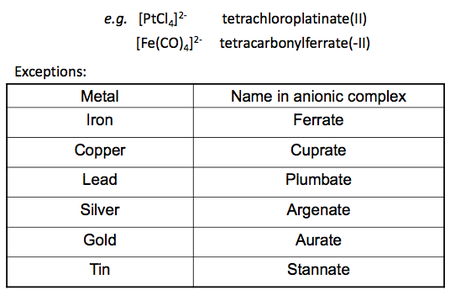
There are also specifications to notes when dealing with the metal centre. Any anionic metal complex will cause the metal name to end in "ate" (e.g. Platinum becomes platinate), whereas all cationic and neutral metal complexes do not. Following on from this rule, a further specification can be made for certain metals where heir anionic names will not only end in "ate" but take on their original Latin name ending in "ate". Below is a table summarising the names for most common ligands and the names of some anionic metals.
Stability/Formation Constants, Kf
The stability constant is an equilibrium constant for the formation of a complex in solution.
It is a useful tool especially in ligand substitution processes because it allows calculation of thermodynamic values such as ΔG, ΔS, ΔH.
General example: General formation constant equations
Denticity
Denticity = defines the number of atoms within a ligand that are coordinated to the metal centre (this is not the same as eta).
| Donor Atoms | Name |
|---|---|
| 1 | Monodentate (unidentate) |
| 2 | Bidentate (didentate) |
| 3 | Tridentate |
| 4 | Tetradentate |
| 5 | Pentadentate |
| 6 | Hexadentate |
Monodentate Ligands
A lot of simple ligands are monodentate, coordinating to the metal through only one atom.
Several factors affect the stability of monodentate complexes:
Ion size and charge
For complexes involving NON D-BLOCK metals, the stability of complexes decreases with increasing cation charge.
Thus, for a given ligand L, a complex involving Ca2+ as a centre is more stable than for Sr2+ and Ba2+ (Ca2+ > Sr2+ > Ba2+).
This is due to the more diffuse s-orbitals as the cation grows larger and heavier, thus creating a weaker orbital overlap with the ligand, decreasing the stability.
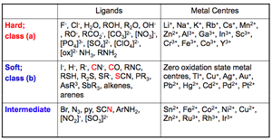
"Hard" and "Soft" metal centres or ligands
Hard = less polarisable
Soft = more polarisable
Hard metal centres form more stable complexes with hard ligands.
Soft metal centres form more stable complexes with soft ligands.
Bidentate Ligands
Bidentate complexes involve two atoms within the ligand binding to the metal, creating what is known as a chelate ring.
The most common chelate rings formed by bidentate ligands are 4-, 5- and 6-membered, depending on the number of atoms separating the two binding atoms.
| Ring size | Examples |
|---|---|
| 4-membered | 
|
| 5-membered | 
|
| 6-membered | 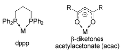
|
Tridentate
Here are a few examples of the possible tridentate ligand conformations.
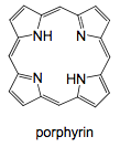
Tetradentate
Here are a few examples of the possible tetradentate ligand conformations.
| Open-chained | Macrocyclic | Tripodal |
|---|---|---|
 |
 |

|
Pentadentate and Hexadentate
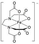
The following compounds are useful in medical applications.
| H-EDTA3- | EDTA4- |
|---|---|
 |
|
Macrocyclic Ligands
Ligands of very high denticity have been synthesised and have important roles in the protection of cations.
These large ligand rings mostly contain O, N and S as the chelating atoms.
The most common examples are crown ethers.

| Type | Examples |
|---|---|
| Crown Ethers | 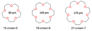
|
| Thia-Crown Ether | 
|
| Aza-Thia-Crown | 
|
| Cryptand | 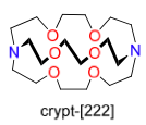
|
Cryptand is especially useful in the isolation of cations. In the example above, it can be seen that a crown ether will coordinate around the potassium cation and protect it from side-attacks, but the cation will still remain coordinated to the silicon atom in the other ligand. Cryptand successfully dissociates the potassiom ion from the silyl anion group and protects it completely from any attack.
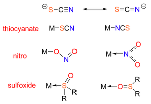
Ambidentate Ligands
Ambidentate ligands are capable of donating electrons from more than just one donor site. Nevertheless, they are not able to donate from these two sites at the same time!
This gives rise to ligand isomerism. Important examples of ambidentate ligands are given below.
Constitutional Isomerism in Coordination Chemistry
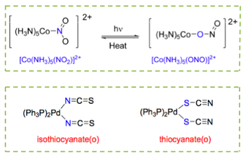
Linkage Isomerism
Linkage isomerism occurs when two ligands have the same empirical chemical formula, but bind to the metal centre via a different donor atoms. This concept applies to ambidentate ligands. To make the distinction between the two isomers, the ligand is written with its donor atom first. A couple of examples are shown below:
Ionisation Isomerism
This type of isomerism occurs when different ions are exchanged from the primary coordination sphere to the second. This means that different ionisation isomers will release different ions in solution, often leading to different colours in solution and different reactions when in the presence of certain compounds. For example:
Further examples include hydrates of ions and the interchange of the water ligand within different cordination spheres.
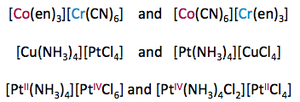
Coordination Isomers
Occurs when ligands are distributed differently between two (or several) metal centres. Examples:
Polymerisation Isomerism
Occurs when n varies within the empirical formula [MLm]n. For example:
[Pt(NH3)4][PtCl4] and [Pt(NH3)2Cl2] both have the common empirical formula [Pt(NH3)2Cl2]n
Ligand Isomerism
As the name suggests, this is simply the ligand in different isomeric forms, e.g. iso- versus normal.
Stereoisomerism in Coordination Chemistry
Geometrical Isomerism
A few of the most important and common types of geometrical isomerism to be familiar with are the following (that can also occur for other geometries):
Conformational (Polytopal) Isomerism
This type of isomerism is possible for any coordination number that has more than one known stereochemistry. It's importan to make sure there is comparable stability between the two conformations and an energy barrier significant enough to prevent their interconversion. Examples of such cases are compounds that can exist both as tetrahedral and square planar, or as trigonal bipyramidal and square-based pyramidal.
Optical Isomerism
This type of isomerism clearly refers to enantiomers, isomers that are non-superimposable "mirror images" of each other.
| Geometry | Enantiomers | Geometry | Enentiomers |
|---|---|---|---|
| Tetrahedral | 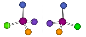 |
Octahedral | 
|
This kind of chiral enantiomerism can also apply to bidentate ligands. In cases like these, the ligands become comparable to "blades" that will rotate only in a certain fashion, and that are completely different to the enantiomeric form of the propeller. The following diagrams help differentiate between the left-handed and the right-handed enantiomers.
Transition Metal Electron Count and Geometries
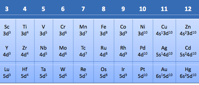
d-Electron Count
The d-electron count of a TM is a useful tool used to describe the electron configuration and valence electron count of the metal in a coordination complex.
It helps understand the reactivity and coordination of the metal, as well as the magnetic properties of a complex.
The general formula for the electron configuration of a TM is: [Noble Gas]s2dn-2
In a neutral TM complex, the d-electron count will be dn.
Oxidation of the complex will lead to removal of d-electrons from the valence shell.
Reduction of the complex will lead to addition of electrons to the d-electron count.
(This can be remembered using the old "OIL-RIG" - oxidation is loss, reduction is gain).
Another way of working out the d-electron count is to know the oxidation state of the metal, and vice versa.
A useful formula to remember is: d-electron count = metal group number - metal's oxidation state
The following table gives some examples of the application of this formula.
| Complex | Oxidation State | Group Number | d-count | Complex | Oxidation State | Group Number | d-count |
|---|---|---|---|---|---|---|---|
| [NiCl4]2- | +2 | 10 | 8 | Cr(NH3)6]3+ | +3 | 6 | 3 |
| [Ni(CO)4] | 0 | 10 | 10 | [MnO4]- | +7 | 7 | 0 |
| [MnCl4]2- | +2 | 7 | 5 | [Mn(CO)4]3- | -3 | 7 | 10 |
| [Fe(H2O)6]3+ | +3 | 8 | 5 | CoCl2(en)2]+ | +3 | 9 | 6 |
| V(CO)6]- | -1 | 5 | 6 |
Werner's Complexes
Alfred Werner (1866 - 1919) can be considered the founder of coordination chemistry for he was the first to make the link between the colour of a complex and the geometry of the complex. He obtained the Nobel Chemistry Prize in 1913 for his work involving the reaction of CoCl3 and NH3.
The following table lists the various compounds and their colour.
Werner's Postulates
The coordination around the cobalt centre remains constantly octahedral.
The colour changes occur due to the differing number of chlorine atoms that are becoming covalently bound to the metal.
Werner was the first scientist to introduce the concept of octahedral coordination around a metal centre.
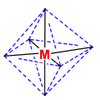
Octahedral coordination occurs when six ligands around the metal coordinate are symmetrically arranged around the metal, yielding eight different faces, hence the prefix octa-. When the octahedral complex is homoleptic, the complex has a point group of Oh. Nevertheless, when there are six ligands, octahedral is not the only possible means of coordination. There exists also trigonal prismatic and planar.
When the ligands start differing, geometrical isomers start to arise. The table below describes the number of geometrical isomers possible for each different 6-ligand configuration.
| Formula | Octahedral | Trigonal Prismatic | Planar | Experimental results |
|---|---|---|---|---|
| MX5Y | 1 | 1 | 1 | 1 |
| MX4Y2 | 2 | 3 | 3 | 2 |
| MX3Y3 | 2 | 3 | 3 | 2 |
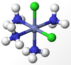
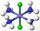
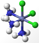
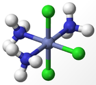
The experimental results for the number of obtained isomers are the same as those for the octahedral complex, indicating that the octahedral geometry is the most probably form of ligand arrangement around the metal centre. The different isomers for an octahedral complex are specified below for Werner's Complexes:
 |
 |
 |
|
| Cis-isomer | Trans-isomer | Facial Isomer | Meridonal Isomer |
The Kerpert Model
The geometry of transition metal complexes cannot be determined simply by using VSEPR Theory. Instead, the Kerpert model rationalises the shape of these complexes by considering the electrostatic repulsions between the ligand groups. Lone pairs of electrons are taken into account, but not as a coordinating groups, just as contributors to the final geometrical name of the structure.
Below is a list of coordination numbers and their geometries.
The Berry Pseudo-Rotation
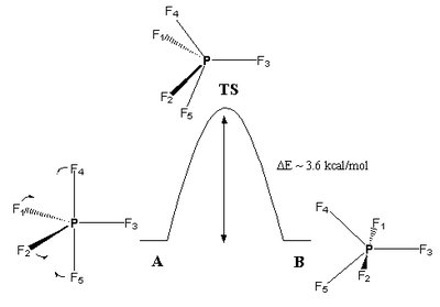
The Berry pseudo-rotation (or Berry mechanism) is a process of isomerisation that was first described by R. Stephen Berry in 1960. It occurs principally for 5-coordinate complexes with trigonal bipyramidal geometries. The isomerisation takes place as two equatorial ligands are exchanged for two axial ones, thus creating a starting and final molecule of trigonal bipyramidal geometry with a transition state whose geometry resembles that of a square-based pyramidal one. The isomerisation is an equilibrium process, which makes the exact geometry of a complex indeterminable except at much lower temperatures (where the fluctuations will occur much more infrequently).
The Berry pseudo-rotation occurs because there is actually a very small energy difference between the trigonal bipyramidal geometry and the square-based pyramidal one. The transition state of square-base pyramidal coordination is thus easily reachable. As well as using thermal energy, the pseudo-rotation can occur when solvents like benzene or cyclohexane approach complexes, causing their geometries to shift to square-based pyramidal (e.g. for Fe(CO)5).
You can see why this is called a "pseudorotation", because the official IUPAC definition of a pseudorotation is: "a conformational change resulting in a structure that appears to have been produced by rotation of the entire initial molecule and is superimposable on the initial one, unless different positions are distinguished by substitution or isotopic labeling. No angular momentum is generated by this motion; this is the reason for the term." So, from the diagram above, it can be seen that the molecule looks like it's undergone a rotation, but looking at the label, the two trigonal bipyramidal molecules are not superimposable.
Crystal Field Theory
Crystal Field Theory is an extremely important tool that explain the loss of degeneracies within metal d-orbitals as ligands/ions are brought closer to the metal along the x-, y-, and z-axis. It allows for the prediction of spectroscopic and magnetic properties of compounds, but is nevertheless a purely ionic model for transition metal complexes.
d-Orbital Splitting Diagrams
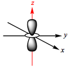
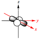
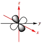
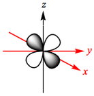
The d-orbitals of a metal are given below:
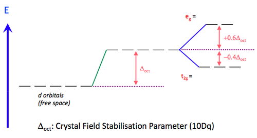
As any number of ligands approaches a metal centre, there is an initial raising of the energy of all d-orbitals. This is known as the Barycentre, when the ligands are considered to approach the metal in a general spherical manner. For an octahedral complex, the raising of the orbitals' energy at the Barycentre corresponds to the octahedral crystal field splitting energy, Δoct. As the ligands get even closer to the metal, new considerations must be taken into account as to which axis the ligand is approaching the metal.
In an octahedral complex, six ligands are approaching the metal centre directly along all three axes, and the strongest interactions will occur between ligands and d-orbitals that hit each other head on. This means that the d(z2) and d(x2-y2) orbitals will be raised in energy relative to the others due to their lobes lying directly along all three axes. The d(xy), d(xz) and d(zy) will actually feel a slight stabilisation relative to the barycentre, because their lobes are in between the axes of the approaching ligands.
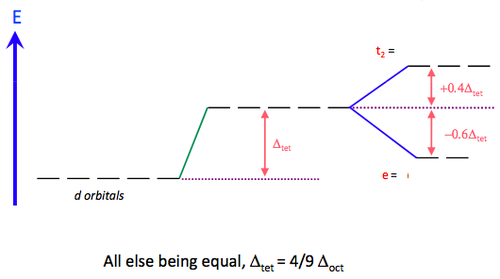
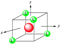
For a tetrahedral complex, the four ligands are approaching in between the three axes. This causes the opposite phenomenon to occur compared to the octahedral d-orbital splitting. The three orbitals d(xy), d(xz) and d(yz) are raised in energy relative to the Barycentre, and d(z2) and d(x2-y2) are lowered, since their lobes are positioned between the axes of ligand approach.
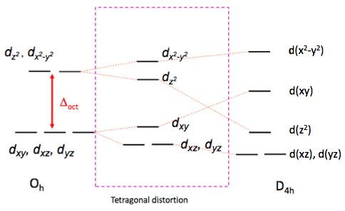
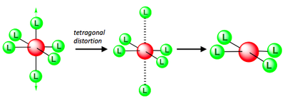
For square planar complexes
High Field and Low Field Ligands
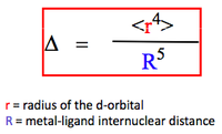
The magnitude of the cystal field stabilising parameter depends both on the metal ion and the nature of the ligand.
It can be defined as:
Ligands that cause a very large crystal field splitting parameter (Δoct, Δtet, etc) are called high field ligands.
Ligands that cause a small crystal field splitting parameter are called low field ligands.
Electrons fill the d-orbitals according to Hund's rule, where orbitals are first half-filled with parallel spins before being doubly occupied. If a ligands is high field, it means that a very large energy gap will exist between the lower set of d-orbitals and the higher ones. This causes the lower-energy set of orbitals to fill up first according to Hund's rule before the higher-energy set starts accepting any electrons. Conversely, if a ligand is weak field, the energy gap separating the wto sets of orbitals is smaller, and so Hund's rule will apply to all the orbitals at once. Both sets of orbitals will be half-filled before any double occupation takes place. In other words, it can be said that:
High field ligands are low spin.
Weak field ligands are high spin.
Another way of explaining this is to consider the relationship of the crystal field stabilisaton parameter with the pairing energy of electrons (P).
Pairing Energy has two constitutional parts:
- Loss of exchange energy, which occurs upon pairing the electrons.
- Coulombic relpulsion between the spin-paired electrons.
Weak field = high spin, which means: Δoct < P
Strong field = low spin, which means: Δoct > P
There isn't really an easy way in which you can predict the field strength of a ligand. Generally, it can be said that:
π-acceptor > no π-acceptor > weak π-donor > strong π-donor |
Chemists have come up with an empirically worked-out series, called the Spectrochemical Series, which orders several common ligands according to their field strength. The Spectrochemical Series is given below, from low field to increasingly high field:
Interestingly, it can be noted that all tetrahedral complexes are high spin (weak field). There have never been any recorded examples of tetrahedral complexes where the splitting is great enough to cause electron-pairing. This is due to the fact that Δtet is only about 4/9 Δoct, meaning that it is more favourable to occupy orbitals of higher energy than it is to pair the electrons.
Crystal Field Stabilising Energy (CFSE)
Below are several examples describing the way in which electrons fill the eg and t2g orbitals for high field and low field cases in an octahedral complex.
For d1 to d3 complexes, the situation is straight forward. Electrons fill the orbitals according to Hund's Rule, and so no differentiation is made between low or high field ligands. The crystal field stabilising energies are as follows:
The situation changes for d4 (and above) complexes. In both high spin and low spin cases, the pairing energy of any two electrons must be taken away from the total CFSE. The values given in the image below do not take this into account, so it is important to remember this extra factor. For the low spin d4 complex, for example, the total CFSE will be 1.6 Δoct - P.
It should also be noted, that the values of CFSE in these diagrams have been noted as an overall positive value of Δoct, compared to the diagrams in the d-orbital splitting diagram section, which have the signs reversed. This is due to the fact that CFSE includes the word "stabilising" which automatically insinuates that the energy value will be negative since it is a stabilising energy (if that makes any sense?... Look at the 2nd year module of coordination chemistry for some more in depth explanations).


