Rep:Phys:sb807
Physical Computational exercise
Cope Rearrangement Tutorial
In this section of the physical computational lab we will examine 1,5-hexadiene and its reactivity as a substrate for the cope rearrangement. The objectives will be to:
1.Locate the energy minima and transition structures on the C6H10 potential energy surface.
2.To determine the preferred reaction mechanism.
The cope rearangement reaction mechanism is shown below (in 2D). Due to the 6 carbon back bone having multiple (e.g Gauche and anti) configurations it was reported by Gung et al [1] that there are twenty seven theoretical conformations, however the symmetry of 1,5-hexadiene and the enantiomerism of the conformations leave only 10 energetically distinct conformers.
1a: Anti 1,5-Hexadiene
The first structure built and 'cleaned' in Gaussview was one of the hexadiene with all four central carbons in an antiperiplanar conformation. This was done by connecting 6 tetrahedral methyl centres, followed by removing the hydrogens at carbons 1, 2, 5, and 6 and placing in the double bonds. The dihedral angles were then all changed to 180 degrees, and the stucture 'cleaned'.
The structure was optimized with a 3-21G basis set using the 'Hartee Fock method'. The energy was reported after optimization to be -231.69260236 a.u., and it had a C2 point group.
1b: Gauche 1,5-Hexadiene
The next structure was built using the same method but this time the dihedral angles were all set to 60 degrees (i.e gauche). The structure was again optimised with the 3-21G basis set using %mem250mb. One would expect this new structure to have a lower energy primarily because of the well reported Gauche effect which is present here. However the gauche effect works predominantly in favour of electronegative substituents such as flourines (due to donation of the C-H σ bonding orbital to the C–F σ* orbital). There are no such electronegative subsituents here and so I would expect the anti structure to be more stable.
The energy of the new structure was recorded at -231.69153035 a.u., and its point group was C1. This is indeed higher in energy than the anti configuration in the first confomer I optimised.
1c/d/e: Predicting/finding the lowest energy confomer
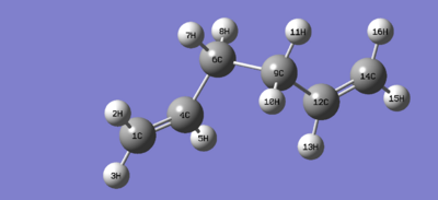
The lowest energy confomer must have a mixture of gauche, and anti centres. Gauche, because the of the 'gauche effect' present and anti to reduce interactions. The structure in part a (i.e the first confomer optimised) is the confomer anti1 in the appendix. The stucture in part B is known as gauche4 in the appendix in the lab script.
My predicted structure of the lowest energy confomer was optimized using a 3-21G basis set, %mem250MB. Energy of my conformer was reported as -231.69253530 a.u. and the point group Ci. This was identified as the anti2 structure in the appendix.
 |
 |
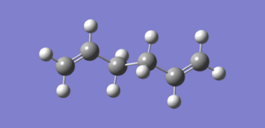
1f: Further optimisation of the anti2 structure
The anti2 structure isolated from the previous exercise was further optimised using the B3LYP/6-31Gd method and basis set. The new energy of the molecule was reported as -234.61171035 a.u.
The table below shows both the HF/3-21G, and DFT/B3LYP(6-21Gd) geometries together so that we can see how the geometry has changed.
| HF(3-21G) | DFT/B3LYP(6-31G,d) |
|---|---|
| 231.69253530 a.u. | -234.61171035 a.u |
On inspection the geometries do not seem to be significantly different. However on closer examination the more optimised geometry has has the carbon 3 hydrogen line up more with the alkene of carbon 1 and 2. That is, there slightly less deviation in the dihedral angle (3.85 degrees) whereas in the less optimised structure (HF/3-21G) the hydrogen seems to have a slightly larger dihedral angle (6.78 degrees) at this point. This can be seen in the Jmols in the table above.
In conclusion the higher basis sets optimisation produces a more 'clean' geometry as everything (especially dihedral angles) is slightly sharpened up.
1g: DFT/B3LYP(6-31G,d) Frequency analysis and more
The optimised structure from 1f was subjected to a frequency analysis of the same basis set. The vibrations were selected and under the results tab and examined. The IR spectrum is shown below:
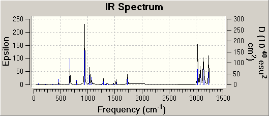
The imaginary frequency was found to be at ~817cm-1. The modulus of this is shown on the spectrum above.
The next item to be examined was located in the ‘View File’ section of the ‘results’ tab. After scrolling down to the section beginning ‘Thermochemistry’ the following energies were reported:
| Property | Value |
|---|---|
| (i) Sum of electronic and zero-point Energies | -234.469204 a.u. |
| (ii) Sum of electronic and thermal Energies | -234.461857 a.u. |
| (iii) Sum of electronic and thermal Enthalpies | -234.460913 a.u. |
| (iv) Sum of electronic and thermal Free Energies | -234.500777 a.u. |
Optimizing the "Chair" and "Boat" Transition Structures
This section involves setting up a transition structure optimisation by computing the force constants at the beginning of the calculation, using the redundant coordinate editor, and using QST2.
2a: Building and optimising an allyl fragment
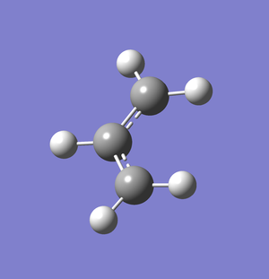
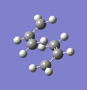
An allyl fragment was drawn in Gausview and optimised using the ‘Hartree Fock’ method and 3-21G basis set. Two of these optimised allyl groups were then placed next to each other (2.2Å apart) in the ‘create molgroup function’ on Gausview
2b/c/d: Optimising the chair transition state
A new Molecule group was created and my guess structure was copy and pasted into the window. The Gaussian optimization for the transition state was set up: Job Type > Opt+Freq > TS (Berny). The force constants were calculated once and in the Additional keyword box at the bottom, Opt=NoEigen was entered.
Noeigen prevents the gaussview from crashing if more than one imaginary frequency (i.e the freqeuncy responsible for the reactions) is detected. This would only happen if the initial transition state guess was very innacurate. The resulting structure is shown as a jmol in the table below. The imaginary freqeuncy was found at -817.86cm-1 and an image of the displacement vectors is shown below:
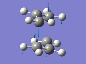
The displacement vectors suggest that this is indeed the vibration for the cope rearrangement. For the next calculation Redundant Coord Editor was selected. The terminal carbons from the allyl fragments which form/break a bond during the rearrangement were selected to be bonds instead of unidentified, and Freeze Coordinate instead of Add was selected. The value of the frozen bonds was set to 2.2Å as suggested. The job was submitted and the results are shown in the table below as the 2c jmol.
For the next calculation the Redundant Coord Editor was opened and for the bonds that were previously frozen Derivative instead of Add was selected. This time a transition state optimization without force constants calculation was set up. The job was then submitted.
| Calculation | 2b | 2c | 2d |
|---|---|---|---|
| Jmol of result | |||
| Calculation method | TS Berny | TS berny | TS Berny |
| Bond forming lengths (Å) | 2.01899 | (not required) | 2.02074 |
| Bond breaking lengths (Å) | 1.38942 | (not required) | 1.38923 |
Comparing the bond breaking and forming lengths between the transition state structures calculated in 2b and 2d, there seems to be very little difference. The only minor change is that both lengths are shorter in the calculate for 2d above.
2e: Optimising the boat transition state
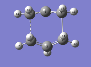
The anti2 structure was opened and two separate molecules copied and pasted into two simulataneous windows. The atom list was edited as suggested and a TS(QST2) optimisation run. As stated in the script the job failed. The chk file was opened and the image was one of a transition state that looked as if it could not be possible (theoretically). The wrong ends of the allyl fragmenst are connected, one by a bond, and the other by a transitional bond (dotted bond, not shown in jmol) (see ).
The guess transition structure was optimised by changing the central dihedral angle and the two central bond angles. A QST2 transition state structure was run again. This failed again for some unknown reason (it was attempted a further 6 times before I decided to start again).
A few changes had to be made to the input file such that it read: # opt=(calcfc,qst2,noeigen) freq=savenormalmodes hf/3-21g geom=connectivity. This file worked and produced the following transition state:
2f: Intrinsic Reaction coordinate
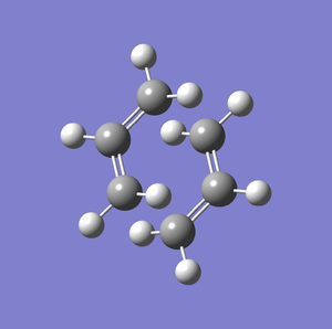
The next method employed in this exercise was the Intrinisic Reaction Coordinate method. For the first calculation an optimised chair transition structure was subjected to a: Forwards only, Calculate force constants once, compute 50 N points, IRC calculation. This produced the following result as the final geometry (iteration 27):
 |
 |
 |
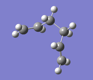
The jobs was then repeated with the Force constants:Always function selected instead. The final geometry of the calculation looked as follows (iteration 48):
 |
 |
 |
We can see from the image above that the calculation is steadily approaching a minimum (i.e the 1,5-hexadiene conformation for the reactant). To see if I could improve the calculation further I ran another calculation, this time with the force constant calculated always, and the number of N computed steps set to 100 instead of 50. This job immediately failed and so did N=75, no a more realistic N=60 was set. The final geometry looked like the following:
 |
 |
The extra 10 points of compution have made very little difference to the final geometry, as shown by the reaction/path graphs. The reactant has indeed reached its starting minimum energy. The energy of this final structure is -231.69165611 a.u. which is closest to that of gauche2 in the appendix (-231.69167 a.u.).
2g:Calculating activation energies
Diels Alder Cycloaddition
1.Building and optimising Cis-Butadiene
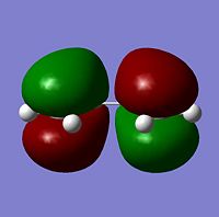
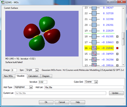
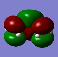
The cis butadiene was optimised using the HF/3-21G method. The HOMO and LUMO are shown below. The LCAO equivalents are also shown for comparison
 |
 |
 |
 |
2.Computation of the Transition State geometry
The bicyclo suggested structure was built and as instructed the extra ethylene unit removed to leave an 'envelope' type transition state structure. The structure was cleaned and a simple TS Berny optimisation (HF/3-21G), opt=noeigen was run.
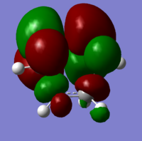
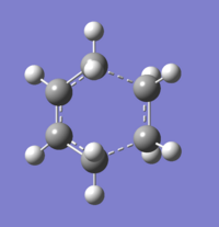
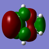
The transition state is shown below, along with the HOMO and LUMO:
 |
 |
 |
The calculation was extended further with a redudant coordinate edit setting for the bonds (frozen to 1.8Å). The result is shown below:
 |
 |
 |
The geometry of the TS Berny is analysed in the table below:
| Property | Value/Diagram |
|---|---|
| C-C Bond lengths (Å) | 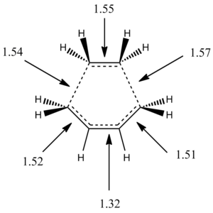 |
| Angles (degrees) | 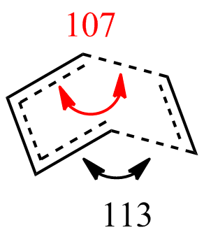 |
3.Study the regioselectivity of the Diels Alder Reaction
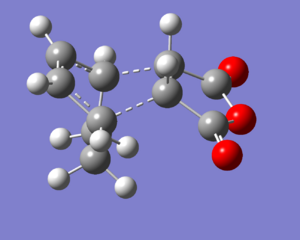
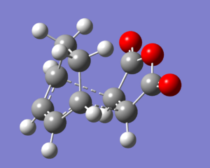
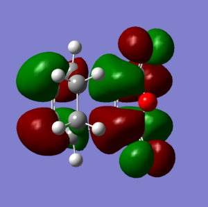
For this final section of the report, the transition structure of the Diels-Alder reaction of Maleic anhydride with Cisbutadiene will be studied. This has been shown to be experimentally very facile (due to the HOMO-LUMO interaction being very favourable). It has been shown [2] that the endo product is kinetically favoured over the exo product (due to a balance of several energy terms, including electrostatic attractions, and closed-shell repulsions). This must mean that the transition state must be lower in energy for the endo reaction.
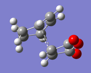
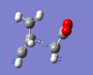
Using the techniques learnt in this lab (i.e. during the cope rearrangement tutorial) we can locate the energies of the transition structures. This will be done by performing a TS Berny calculation on a guess of the transition structure. The transition structures were built in gaussview using the bicyclo and THF fragments.
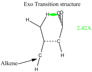
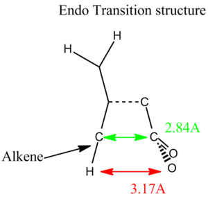
Below (Table. 1) are images of the initial guesses, and the exo and endo transitions structures, along with their energies and HOMO, LUMOS and imaginary frequencies. Since I used the TS Berny method, the transition structure initial guess had to be quite good otherwise the job failed. This meant that a lot of trial and error was involved in getting the transition state structure optimisation to head to the right minimum (if at all!)
Disscussion
From the table above we can see that the Endo transition structure has a lower energy than that of the exo transition structure. This supports the experimental data. Both are definitely transition state structures because we can tell by the imaginary freqeuncies (which are definatley showing Diels-Alder mechanisms). The main structural difference is that in the exo transition state the bridge closer to the maleic anhydride region contains two sp3 carbon centres which have hydrogen atoms sticking into the plane of the maleic part of the entire molecule. For the endo transition state the bridge closest to the (CO)-O-(CO) region of the maleic anhydride is sp2 hybdrised. This means that the bridge is planar and doesn't protude into the direct vicinity of the (CO)-O-(C0) region. (It is most likely) For this reason (that) the exo form is slightly more strained.
References
- ↑ B. Gung et al DOI:10.1021/ja00111a016
- ↑ J.I.García, J.A. Mayoral, L. Salvate DOI:10.1002/ejoc.200400424

