Rep:Naf:physical
Module 3: Physical
The Cope Rearrangement
Optimising the Reactants and Products

a) A molecule of 1,5 hexadiene was drawn using GaussView. The four central C atoms were drawn with an antiperiplanar arrangement, this was modified by changing the dihedral angle to 180 degrees. The structure was cleaned using the clean function. Then the structure was optimised using the HF/3-21G method and basis set. The structure shown was obtained.
Total Energy = -231.69260235 a.u. Point group = C2
A point group was not initially obtained in the summary but the symmetry had to be relaxed by selecting the symmetrize function.
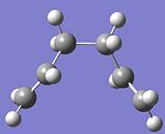
b) The same compound was drawn but this time with a gauche conformation. The dihedral angle of the four central C atoms was changed to 60 degrees. The structure was optimised as above using the HF/3-21G method and basis set. The structure shown was obtained.
Total Energy = -231.69166698 a.u. Point group = C2
I would expect the anti conformation to have a lower energy, when comparing the energy values the anti total energy is found to be lower. This would be because of the steric clash of the hydrogens in the gauche conformation. The four hydrogens at the top of the structure would be in close proximity, the optimised structure has the hydrogens staggered not eclipsed but there would still be an increase in energy due to this.

c) From my results from above I would predict that the lowest energy form of 1,5 hexadiene would be similar to the anti structure found in part a but the two groups with the double bonds should be on different sides of the compound. This was done by opening the structure from part a in Gaussview and changing the dihedral angle of the 4 carbons, starting from the first carbon on the left to the negative of what the current angle was. The structure was optimised as above using the HF/3-21G method and basis set. The structure shown was obtained.
Total Energy = -231.69253528 a.u. Point group = Ci
However this energy is actually higher than in part a so the minimum energy conformation was not found.
d)
| My structure | Energy a.u | Point Group | Structure from appendix 1 | Energy a.u | Point Group |
|---|---|---|---|---|---|
| Part a | -231.69260 | C2 | anti1 | -231.69260 | C2 |
| Part b | -231.69167 | C2 | gauche2 | -231.69167 | C2 |
| Part C | -231.69254 | Ci | anti2 | -231.69254 | Ci |
The structures I have obtained look the same, have the same point group and the same energy as those from appendix 1. The energy values for my calculations were rounded to 5 d.p, so they were the same as those in the appendix.
e) The anti2 conformation has already been located and has the same energy as that in the appendix.
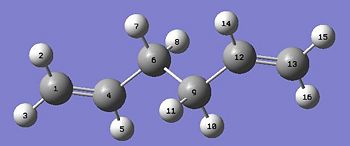
f) The geometry was then optimised using the DFT B3LYP/6-31G* method and basis set. The energy bond angles and bond distances for this structure was then compared to the structure using the lower theory HF/3-21G. These values will then be compared to literatue.
| HF/3-21G calculation a.u | B3LYP/6-31G* calculation a.u |
|---|---|
| -231.6 | -234.6 |
| Bond | HF/3-21G calculation length/Å | B3LYP/6-31G* calculation length/Å | Literature/Å [1] |
|---|---|---|---|
| C1-C4 | 1.32 | 1.33 | 1.34 |
| C4-C6 | 1.51 | 1.50 | 1.51 |
| C6-C9 | 1.55 | 1.55 | 1.54 |
| C9-C12 | 1.51 | 1.50 | 1.51 |
| C12-C13 | 1.32 | 1.33 | 1.34 |
| Angle | HF/3-21G calculation angle ° | B3LYP/6-31G* calculation angle ° | Literature [2] angle ° |
|---|---|---|---|
| C1-C4-C6-C9 | 114.7 | 114.7 | 116.0 |
| C4-C6-C9-C12 | 180.0 | 180.0 | 176.8 |
| C6-C9-C12-C13 | 114.6 | 114.7 | 116.0 |
The dihedral angles are exactly the same for both calculations and the bond lengths are only slightly different. The calculations are similar to the literature. Calculating with the better method and basis set reduced the energy of the structure but there is not much change in the geometry so for this compound using the lower level method and basis set is sufficent as it takes less time and costs less.
g) A frequency analysis of the anti2 structure was carried out using the optimisation from the B3LYP/6-31G* calculation. The frequency values were checked to make sure all vibrations were positive to confirm the optimisation was at a minimum. The following energy values were obtained from the frequency analysis.
| Type of Energy | Energy/Hartree |
|---|---|
| (i) the sum of electronic and zero-point energies | -234.469212 |
| (ii) the sum of electronic and thermal energies | -234.461856 |
| (iii) the sum of electronic and thermal enthalpies | -234.460912 |
| (iv) the sum of electronic and thermal free energie | -234.500821 |
Optimising the Chair and Boat Transition Structures
Optimising the Chair Transition Structure
a) An allyl fragment was drawn, CH2CHCH2 and optimised using the HF/3-21G method and basis set. The log file not the checkpoint file had to be opened otherwise the structure stayed the same as it was initially drawn. Two of the allyl fragments were orientated to look like the chair transition state.

b) The guessed chair transition state was then optimised and a frequency analysis was carried out using HF/3-21G. Optimization to a TS (Berny)and calculating the force constants once were chosen, the addition keyword Opt=NoEigen was added. The job completed successfully and the structure shown looks like the one in the appendix. It has a imaginary vibration at 818cm-1 which when animated corresponds to the cope reaction. The distance between the terminal ends of the allyl fragments are 2.02 Å.
c) The transition structure was then optimised using the frozen co ordinate method. The two terminal allyl bonds were frozen to 2.2 Å using the redundant co ordinate editor. The structure was then optimised using the HF/3-21G method.
d) The bond forming/breaking bonds which were frozen were then optimised using the redundant co ordinator but using the derivative instead of the frozen co ordinate. The transition state looks very similar to the diagram already shown. The bond forming/bond breaking lengths for this structure are 2.02 Å (2dp). This is the same as the previous method.
Optimising the Boat Transition Structure
e) The boat transition structure structure will be optimised using the QST2 method. The producs and reactants have to be specified so the labelling on the product needed to be changed. The molecules in the input file are shown. An opt+freq calculation was set up, optimisation to a TS (QST2) was chosen. The method and basis set was HF/3-21G. The job fails, on inspection of the checkpoint file the transition structure looks like a dissociated form of the chair transition state. The calculation can not rotate around the bonds, it just translates the top allyl fragments
 |
 |
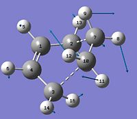
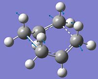
The geometries of the reactant and product were then modified to more like the boat transition structure. For the product the dihedral angle of C2-C3-C4-C5 was changed to 0o and the angle between C2-C3-C4 and C3-C4-C5 was changed to 100o then the same was done for the products as shown below. The QST2 calculation was run again as above but this time the calculation did not fail and the transition state was obtained. There was one imaginary frequency obtained at -840cm-1 which corresponds to the rearrangement, the motion is shown by the arrows on the digram below. This example shows that for QST2 the starting geometries of the reactant and product have to be similar to the transition state.
 |
 |
 |
The IRC method for the boat and chair
(f) Looking at the optimised structure for the chair transition state it looks like it connects to the gauche2 conformation and looking the the optimised structure for the boat transition state it also looks like it connects to the gauche2 conformation. However it is not possible to tell this exactly from looking at the diagrams so calculations using the Intrinisic Reaction Coordinate method were run for the optimised chair and boat conformations to follow the structure's minimum energy path from a transition structure to it's minimum. The job chosen was IRC and the reaction was only followed in the forward direction. The force constant was only calculated once and the number of points was set to 50. For both the conformations the geometry did not reach a minium so error message were produced. However the log files could be opened and the geometry of the last step is shown below. The chair conformation took 27 steps and the boat 30 steps.
 |
 |
To reach a minimum for these structures the third option which was most reliable method was chosen. The calculation was re run but the force constants were computed at every step. Both calculations ran and completed successfully. These are shown below. The chair conformation completed in 47 steps and looks like the gauche2 conformation. The energy of the calculation was -231.691 hartrees is the same energy as the gauche2 conformation . The boat conformation was compleeted in 47 steps and does not look that similar to any of the conformations. The energy of the calculation was -231.683 hartree which is close to the calculated energy of the gauche1 conformation which has an energy of -231.687 hartree
 |
 |
Activation Energies
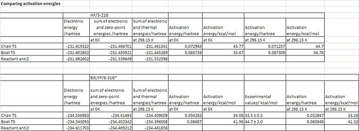
The optimisations for both transition states at a HF/3-21G level were further optimised using a higher level basis set, B3LYP/6-31G*. The geometries of both of the optimisations with the low level basis set and the higher level basis set are very similar however the energies are different. This shows the better accuracy of the higher basis set. A frequency calculation was also carried out. The activation energies of both transition states were calculated by subtracting the sum of reactant electronic and zero point energy from the sum of electronic and zero-point energy for the chair ts. This was also done with the thermal energies. All this information is summarised in the table below and the activation energy at OK is compared to the experimental values given in module 3. The data shows the activation energies are much closer to the experimental values for the B3LYP/6-31G* method. For the chair transition state the calculated value is within the experimental range. However for the boat transition structure the calculated value is slighlty out of the experimental range. The calculations do however show that the cope rearrangement is more stable when it proceeds via the chair transition state.
The Diels Alder Cycloaddition

This is the first diels alder reaction that will be investigated. A diels alder reaction is a pericyclic reaction where the π orbitals of the dienophile form new σ bonds with the π orbitals of the diene. This reaction will be investigated to see whether the HOMO and LUMO of both the reactants can interact and the transition state will be modelled. This reaction is a [4s + 2s] because it involves 6 electrons, 4 from butadiene and 2 from ethylene, this can be seen in the reaction scheme.
i)
Gaussview was used to build cis butadiene, it was optimised using AM1 semi-empirical molecular orbital method and then a further energy calculation was carried out using pop=full as an addition keyword to generate MOs. This was also done for ethylene to see if there is can be a HOMO-LUMO interaction between the two reactants. The reaction will be allowed if the HOMO and LUMO of the different reactants have the same symmetry.
| MO - butadiene | picture of MO | symmetry | MO- ethylene | picture of MO | symmetry |
|---|---|---|---|---|---|
| LUMO | 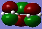 |
s | LUMO | 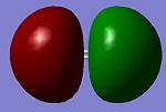 |
a |
| HOMO |  |
a | HOMO |  |
s |
From investigating the molecular orbitals it can be shown that the symmetry of the HOMO and LUMOS show that they can interact
ii)
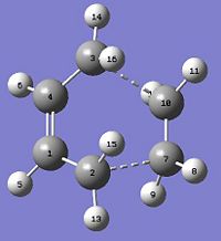
The transition state of the reaction was computed using the frozen coordinate method. The transition state was modelled in GaussView as shown in the script. The ends of the reactants where new bonds were being made were frozen at 2.2 Å then an optimisation to a minimum was carried out. Then these bond lengths were optimised by setting changing the calculation to a hessian guess for the derivate of the bonds. An opt and freq to a TS was carried out at the transition structure was obtained.
The bond lengths of the partly formed C-C bonds between C3-C10 and C2-C7 are both 2.119 Å. Typical sp3 C-C bondlengths are 1.54 Å , typical sp2 C-C bond lengths are 1.33Å. The van der Waals radius of the C atom is 1.70Å. This shows that the bond is longer than typical double or single bonds but is shorter than radius of two C atoms so it shows a bond is forming. The bond length C7-C10 which was the double bond is ethylene is 1.38Å which shows this bond is loosing its double bond character. The C1-C4 bond is 1.40Å which shows it is forming double bond character.
An MO calculation was done as before, using an energy calculation and using pop=full as the addition keywords. The method was the same for the optimisation. The HOMO and LUMO of the transition state were visualised and can be seen below.
| MO | picture of MO | symmetry |
|---|---|---|
| LUMO | 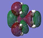 |
s |
| HOMO | 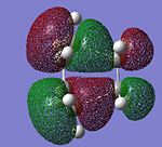 |
a |
The symmetry shows that it is the HOMO of the butadiene and the LUMO of the ethylene which interact to form the HOMO of the transition state. If we look at the energies of the antisymmetric HOMO and LUMO from the MO calculation the energy gap = (0.05284- -0.34455) = 0.3974 au whereas the energy gap between the symmetric HOMO and LUMO = (0.01796- -0.38777) = 0.4057 au. The smallest energy gap leads to the most favourable interaction which is why the HOMO of the butadiene and the LUMO of the ethylene which interact to form the HOMO of the transition state. This reaction is allowed because the symmetries of the overlapping obitals are the same and their energies are close enough so the MOs can overal. This reaction has 6 electrons which means its follows the 4n+2 huckel transition state rule which shows only suprafacial components. This corresponds to what the MOs show.
iii)

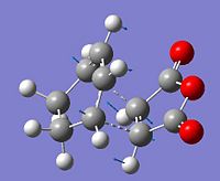
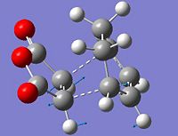
The regioselectivity of the diels alder reaction between cyclohexa-1,3-diene and maleic anhydride will be investigated. The main product is the endo form. The transition states for both products was modelled using the QST2 method, the reactants and products were modelled to generate the transition state. They were all drawn on GaussView and optimised using the AM1 method. The reactants had to be positioned correctly and the C atom distance where the new bonds are forming was set to 2.2Å. Both the transition states are shown below. A frequency analysis was also carried out to make sure the imaginary frequency corresponds to the diels alder reaction taking place.
| exo | endo |
|---|---|
| -0.05042 | -0.05150 |
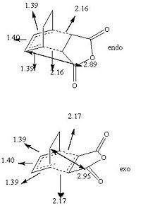
The reason for the product being mainy endo is because of kinetics, the transition state for the endo product is lower in energy. The difference in energy is due to a balance between the strain in the exo form and the secondary orbital overlap in the endo form. The exo form is nore strained due to the steric clash between the -(C=O)-O-(C=O)- fragment and the opposite bridging carbons. The through space distance is shown on the diagram as being 2.95Å. Whereas in the endo form the -(C=O)-O-(C=O)- fragment is opposite the -CH=CH- fragments which leads to orbital overlap. This is shown below.
The new bonds being formed are longer than a typical double or single bond length but as before is shorter than the covalent radius of two C atoms so a bond is forming. The double bonds being changed into single bonds and the single bond being made into a double bond are almost the same lenght. This shows the the bond forming and breaking processing is happening at the same time, this is evidence for a transition state not any intermediates.
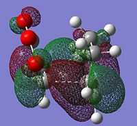
The HOMOs were generated for both transition states
 |
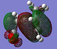 |
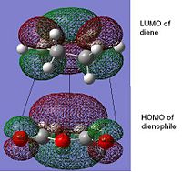
From literature[3] it was found that the secondary overlap in the endo transition state is between the diene LUMO and the dienophile HOMO. Ths overlap is shown for the endo transition state, this is not present in the exo transition state. However if the energy of the HOMO-LUMO gap is calculated = (0.01680--0.44186)= =0.4587 a.u this is quite large and from the orbital picture we can see the seconard orbital overlap contributing from the orbitals around the -(C=O)-O-(C=O) would be small due to the large distance. This suggects that this interaction is small and the possibly the steric hinderance in the exo form is the dominant factor. This idea is also discussed in literature.
References
- ↑ György Schultz and István Hargitta Journal of Molecular Structure Volume 346, 15 February 1995, Pages 63-69 DOI:10.1016/0022-2860(94)09007-C
- ↑ BRANDON G. ROCQUE; JASON M. GONZALES; HENRY F. SCHAEFER III Molecular Physics: An International Journal at the Interface Between Chemistry and Physics, 1362-3028, Volume 100, Issue 4, 2002, Pages 441 – 44DOI:10.1080/00268970110081412
- ↑ Fox et all J. Org. Chem., 1987, 52 (8), pp 1469–1474 DOI:10.1021/jo00384a016


