Rep:Module3:sc2108
Introduction
In this module, set of computational experiments are performed. Firstly, the transition structures on potential energy surfaces for the Cope rearrangement were characterised, that includes optimising geometries and then finding the lowest energies and vibrational frequencies. Then, a Diels Alder cycloaddition reaction was studied as well, using similar methods. In general all these caluclations are done by solving the Schrodinger equation.
The Cope Rearrangement - Tutorial
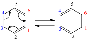
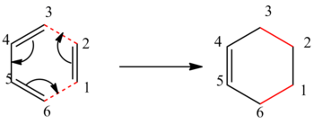
The aims of this experiment were to optimize different geometries of reactants and products and to find the low-energy minima and transition structures of 1,5-hexane [3,3]-sigmatropic rearrangement and thus determine the preferred reaction mechanism. The reaction mechanism has been widely studied and is now accepted that the reaction occurs in a concerted way via chair or boat transition states. It was found that a DFT-B3LYP calculation with 6-31G gives very good results with good agreement to the experiment and that boat conformer is lying several kcal/mol higher in energy than chair. The mechanism of the rearrangement can be seen in Figure 1.
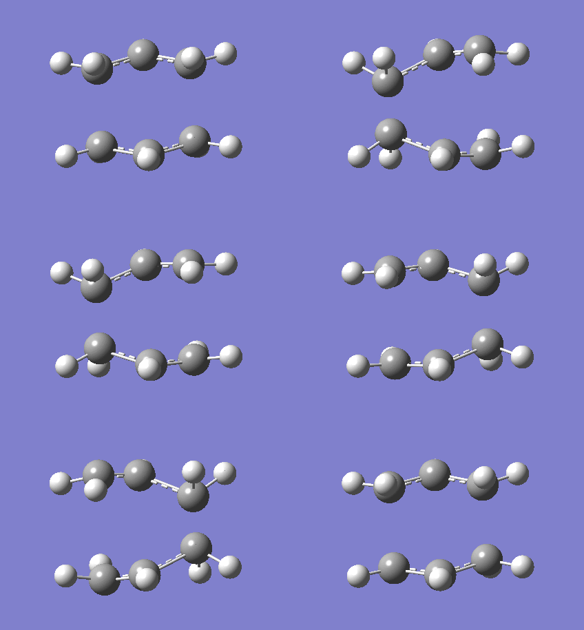
Figure 1: The mechanism of the Cope Rearrangement (left) and boat and chair TS (right)

Optimisation of 1,5-hexadiene
Firstly, a 1,5-hexadiene was drawn with anti-peri-planar conformation (anti-linkage) for the central 4 atoms. The "Clean" command was used in Gaussview in order to get the geometry approximately correct. Then, a Hartree-Fock calculation was run with 3-21G basis set in Gaussian. 10 structures with different energies and conformations were found and finally a structure with lowest energy was achieved. When all calculations were done, it is important to note that a checkpoint file was opened in order to analyse the structure. In the Results tab (Summary) all key information was found and are presented in the table below:
Table 1: Optimisation Summary for HF/3-21G
| Conformer | Point Group | Energy / Hartree (3-21G) | Relative Energy / kcal mol-1 | D-Space Link |
| C2 | -231.68772 | 3.10 | DOI:10042/to-8152 | |
| C2 | -231.69167 | 0.62 | DOI:10042/to-8153 | |
| C1 | -231.69266 | 0.00 | DOI:10042/to-8154 | |
| C2 | -231.69153 | 0.71 | DOI:10042/to-8155 | |
| C1 | -231.68962 | 1.91 | DOI:10042/to-8156 | |
| C1 | -231.68916 | 2.20 | DOI:10042/to-8157 | |
| | C2 | -231.69260 | 0.04 | DOI:10042/to-8148 |
| | Ci | -231.69254 | 0.08 | DOI:10042/to-8149 |
| | C2h | -231.68907 | 2.25 | DOI:10042/to-8150 |
| | C1 | -231.69097 | 1.06 | DOI:10042/to-8151 |
It is first expected that an anti-conformer would be lowest in energy due to sterics. However, it can be seen that the Gauche conformer gave the lowest energy. This is interesting and implys that there are some sort of other interactions that are more favourable than in anti conformers.
Even though only anti2 was suggested to be analysed further with a different method, it was decided all conformers are optimised again using DFT-B3LYP/6-31(d) method in order to see the effect of having a higher method of calculation, but especially to see if the gauche3 conformer is still lowest in energy (or close to the most stable one) so that those favourable interactions - if still observed - are worth being investigated. This can be seen in Table 2.
Table 2: The Optimisation Summary usign B3LYP/6-31G
| Conformer | Point Group | Energy / Hartree (6-31G(d)) | Relative Energy / kcal mol-1 | D-Space Link |
| C2 | -231.60788 | 2.45 | DOI:10042/to-8162 | |
| C2 | -234.61069 | 0.68 | DOI:10042/to-8163 | |
| C1 | -234.61133 | 0.28 | DOI:10042/to-8164 | |
| C2 | -234.61052 | 0.79 | DOI:10042/to-8165 | |
| C1 | -234.60911 | 1.68 | DOI:10042/to-8166 | |
| C1 | -234.60889 | 1.81 | DOI:10042/to-8167 | |
| | C2 | -234.61178 | 0.00 | DOI:10042/to-8158 |
| | Ci | -234.61172 | 0.04 | DOI:10042/to-8159 |
| | C2h | -234.60965 | 1.34 | DOI:10042/to-8160 |
| | C1 | -234.61079 | 0.62 | DOI:10042/to-8161 |
It is very interesting to see that this time, after using a more accurate method, anti1 is the most stable conformer, although anti2 is not far from the lowest energy either and could just as well be the lowest one, depending on how well the calculations were performed at that time. Gauche3, on the other hand is now the third most stable structure and its energy is quite higher than the most stable one - by 0.28kcal/mol and 0.24kcal/mol higher than the anti2 conformer. The next "stable" conformer is anti4 - as expected. Gauche3 has shown some significant stabilisation, independent of which method was used. As gauche conformers were expected to have significantly higher energies than anti conformers, this opened a new question of why that might be the case. Well, there are several things that have to be considered. Sterics is the most obvious reason and explanation one usually considers first. However, in this case the sterics has clearly been overridden and other effects are happening. This is probably due to favourable orbital overlap between the atoms and this indeed has been suggested [1] that there are π-σ* interactions, which are desired in gauche3 conformer and override the sterics, which is the reason for other higher energies in the remaining gauche conformers.
Frequency analysis of anti2 conformer
As suggested in the manual, the frequency analysis was done on anti2 conformer. The starting point was an anti2 structure optimised by DFT-B3LYP/6-31G method, then a frequency calculation was performed keeping the same method and basis set. Why the frequency analysis is important, well one has to be sure that the correct minimum was achieved and not the transition state, so if there are any negative frequencies, calculations have to be performed again as negative frequency would suggest that there are imaginary frequencies and thus a transition state is reached instead of the minimum. Luckily, calculations gave no negative frequencies and so all values can be compared to the literature. Firstly let us compare how the bond lengths and angles changed during different optimisation using different level methods. Different vibrations with highest intensities have been chosen and can be seen here: The frequencies/cm-1 and intesities are: 936.3/72, 1717/18, 3026/53, 3075/38, 3134/53, 3242/44, respectively.
Table 3: Angles and bonds analysis
| HF/3-21G | DFT-B3LYP/6-31G(d) | Literature [2] | |
| Dihedral angles of terminal carbons/° | 114.7 | 119.0 | - |
| Dihedral angles of inner carbons/° | 180 | 180 | - |
| C=C bond/A | 1.32 | 1.34 | 1.34 |
| C2-C3/A | 1.51 | 1.51 | 1.51 |
| C3-C4/A | 1.55 | 1.56 | 1.54 |
It can clearly be seen that a DFT method gives values of bond lengths closer to literature, although values from HF method are very close as well. Also what is interesting is that the higher level method (DFT) gave larger dihedral angle than the lower level method.
In order to obtain energies at 0K, temperature and pressure in input file had to be changed.
Table 4: Thermochemistry analysis
| Measured at 298.15K / Hartree | Measured at 0K / Hartree | Difference / Hatree | Difference / kJ mol-1 | |
| Sum of Electronic and Zero-Point Energies | -234.4162 | -231.5390 | -2.8772 | -7554.08 |
| Sum of Electronic and Thermal Energies | -234.4090 | -231.5391 | -2.8699 | -7534.90 |
| Sum of Electronic and Thermal Free Energies | -234.4479 | -231.5391 | -2.9089 | -7637.20 |
| Sum of Electronic and Thermal Enthalpies | -234.4080 | -231.5391 | -2.8690 | -7532.42 |
Transition states optimisation
Chair
As mentioned before, boat and chair conformations are the two different transition states for this rearrangement. Both involve the same number of carbon and hydrogen atoms, but their shape is different as well as the point groups. Chair belongs to a C2h and boat to the C2v point group.
A CH2CHCH2 - allyl fragment was first drawn in Gaussview. Then this structure was optimised using simple method first - HF/3-21G. Next, this optimised structure was copied twice into a new window and arranged so that the "chair" shape was achieved. A guess of distance was made and so the two molecules were set approx. 2.2A apart.
Figure 2: Optimised chair TS, HF/3-21G
Chair-3-21G |
Two different optimisation methods were used as transition states optimisations are much harder to calculate as the negative direction of curvature has to be known. The easiest way to optimise is to compute the Hessian (force constant matrix) in the first step. One must be careful, though, if the guess structure is far from the correct structure, then the calculation might not work. This can be avoided by freezing the reaction coordinates.
Firstly, the guess structure from above was copied and pasted into the new window. Then a Gaussian optimization for a transition state was set up by selecting Opt+Freq under "Job Type" and the Optimization to a Minimum was changed to Optimization to a TS (Berny). The force constants were calculated Once and Opt=NoEigen was added in the Additional keyword box so that the crashing of the calculation is avoided if more than one imaginary frequency is computed during the optimization.
When this job was returned, the optimisation was performed again by slightly different method. We use, already mentioned, "the frozen coordinate method". A guessed optimised structure from before was again copied and pasted into another window. From the Edit menu, the Redundant Coord Editor is selected where the highlighted file tab at the top left (Create a New Coordinate) is clicked and a line appears where Add Unidentified (?, ?, ?, ?) is shown. Going back to the window, one pair of the terminal carbons from both fragments are selected and in the coordinate editor window "Bond" is selected instead of Unidentified and Freeze Coordinate is selected instead of Add. Then the same process was repeated with the other two terminal carbons. When completed, Gaussian is selected to calculate the optimisation where Opt=ModRedundant is included in the Additional Keywords. The following results are obtained:
Table 5: Optimisation Summary of frozen and non frozen method
DOI:10042/to-8174 , DOI:10042/to-8175
Boat
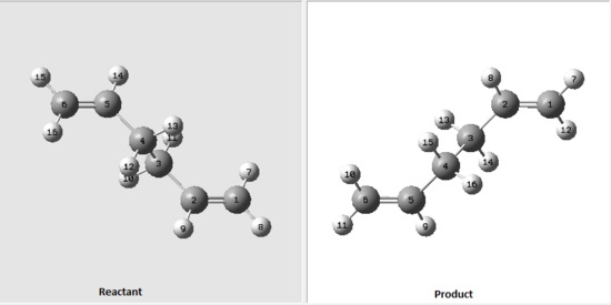
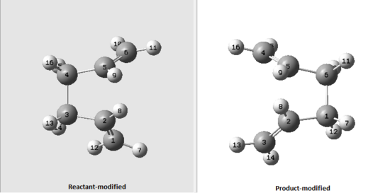
Again a new method (QST2) was used when optimising a boat transition structure. In this method, the reactants and products are specified where the calculations find the transition state between the two. In order to get the calculations correct, reactants and products have to be numbered in the same way, otherwise everything would get confused as carbons and hydrogens will be swapping between eachother so that the transition state is found. The optimised anti2 structure from previous exercise was opened and copied into a new window but this time by using 'Add to MolGroup' instead. That produced 2 of the same molecules within one window (two subwindows) so that both reactant and product can be seen side by side. They were then numbered in the following order:
Figure 3: Numbering of a reactant and product
This two transition states, however are too far from the real ones, so the optimisation calculation failed. In order to "help" the Gaussian to give correct calculations, dihedral angle between atoms 2, 3, 4, 5 on reactant and product molecules was set to 0° and the angle between 2,3 and 4 carbon atoms was set to to 100°, as shown below.
Figure 4: Modified numbering of a reactant and product
This went to successful completion and results are shown in Table below.
Table 6: Optimisation Summary - QST2
| Optimised TS Boat Structure | |
| C-C bond length (terminal) / Å | 2.14 |
| Energy/ Hartree | -231.6028 |
| Imaginary frequency / (cm-1) | -840 |
| Vibration visualisation | 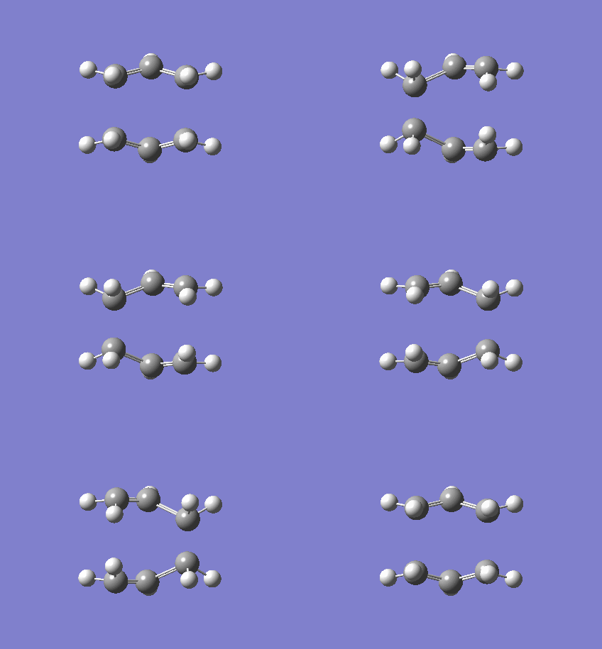
|
Intrinisic Reaction Coordinate
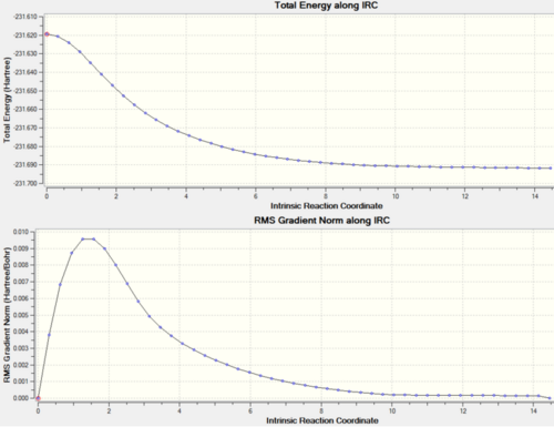
Since it is pretty much impossible to predict which conformer is produced by each transition state an Intrinisic Reaction Coordinate (IRC) calculation is produced, which follows the structure of the molecule along the energy surface. In order to carry out this calculation the .chk file of one of the chair transition states was opened and the job type was set to IRC. Our transition state is symmetric, so we only need to compute in one direction, so a "forward" direction is selected and "calculate force constant" is set to "Once". The default of how many points are calculated is set to 6, this is changed to 50, and the calculation after that to 100. If not enough points are calculated then the end point might not be achieved and so other methods will be tried.
Table 7: IRC analysis
| First IRC calculation - 50 points | Second IRC calculation - 100 points | |||||
| Energy/ Hartree | -231.687 | -231.693 | ||||
| Picture of final set molecule | ||||||
| Actual number of calculated points (from .log) | 23 | 48 | ||||
| IRC graphs | 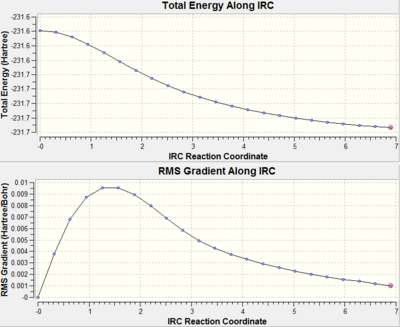 |
|
DOI:10042/to-8179 , DOI:10042/to-8178
Now it can be observed that the conformer of this transition state is Gauche5 conformer from before.
Activation energies
Finally we need to calculate the activation energies for our reaction via both transition structures. In order to calculate the activation energy, the energy difference between the reactant and the transition state has to be found and the transition states have to be optimised using higher level method - DFT-B3LYP/6-31G(d).
Table 8: Comparison of optimised structures of reactant, boat TS and chair TS using two different methods
| Chair TS | Boat TS | Anti2 (reactant) | |||||||
| Optimised via HF/3-21G | |||||||||
| Energy / Hartree (HF/3-21G) | -231.6193 | -231.6028 | -231.6925 | ||||||
| Optimised via B3LYP/6-31G | |||||||||
| Energy / Hartree (B3LYP/6-31G) | -234.5570 | -234.5431 | -234.6117 | ||||||
| D-Space Link | DOI:10042/to-8174 DOI:10042/to-8175 | DOI:10042/to-8173 DOI:10042/to-8173 | DOI:10042/to-8149 DOI:10042/to-8159 |
Table 9: Comparison of activation energies
| HF/3-21G | B3LYP/6-31G(d) | |
| Activation Energy - Chair / Hartree; kcal mol-1 | 0.0732; 45.9 | 0.0547; 34.3 |
| Activation Energy - Boat / Hartree; kcal mol-1 | 0.0897; 56.3 | 0.0686; 43.0 |
It is found that the experimental activation energies for the chair TS is 33.5 ± 0.5 kcal/mol and 44.7 ± 2.0 kcal/mol for the boat TS at 0 K. As can be seen, the Gaussview gave excellent results for higher level method (6-31G(d)) - it is within experimental error, for 3-21G it is, however a bit further apart from the experimental value, but is still of the same order of magnitude.
The Diels Alder Cycloaddition
Cis-butadiene + Ethylene reaction
In the last experiment, the methods that were learnt in previous examples are now applied to other reactions - Diels Alder reactions. They belong to a pericyclic type of reactions. If the interaction between HOMO of one reactant and LUMO of the other is favourable, i.e. one can react with another, then this reaction is allowed. The reaction involves a dienophile (ethylene in our experiment) and a diene (cis-butadiene). Since HOMO and LUMO can interact in our case (as seen from below analysis), this reaction is concerted. Orbitals that overlap have to, of course, be of same symmetry in order for molecule to be stable, i.e. for product to form. If there are any substituents that have π orbitals and have the correct symmetry then this can drive a site of reaction, so that Diels-Alder addition happens on the side of substituent.
Figure 5: Mechanism of Diels-Alder reaction
Firstly, cis-butadiene and ethene were optimised separately and then their HOMO and LUMO were compared in order to see if they "match" and can thus overlap. AM1 empirical method was used. This can be seen below.
Table 10: MO and energy analysis of cis-butadiene and ethylene
| Molecule | Molecular Orbital | MO visualisation | Symmetry | Energy/ Hartree |
| Cis-butadiene | HOMO |  |
Symmetric | -0.357 |
| LUMO |  |
Anti-symmetric | 0.208 | |
| Ethylene | HOMO | 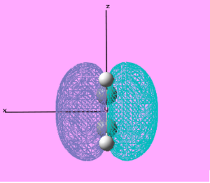 |
Anti-symmetric | -0.395 |
| LUMO | 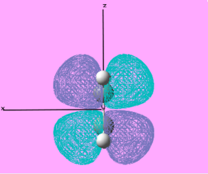 |
Symmetric | 0.162 |
It can be seen that the HOMO of the ethylene and LUMO of the cis-butadiene indeed match and so the reaction is allowed (concerted.
Next, these two fragments were put "together" to form a transition state. A frozen coordinate was used with AM1 empirical method, as it turned out that if the frozen coordinate was not used, the correct minima was not achieved. Then, after that the higher level of method (DFT-B3LYP/6-31G) was used in order to obtain even better results.
Table 11: Energy and vibrational analysis of the product
| Molecule | |||
| Energy/ Hartrees | -234.494 | ||
| D-Space Link | DOI:10042/to-8184 DOI:10042/to-8185 DOI:10042/to-8186 | ||
| Imaginary Frequency/ cm-1 | -518 | ||
| Vibration Visualisation (Imaginary) | 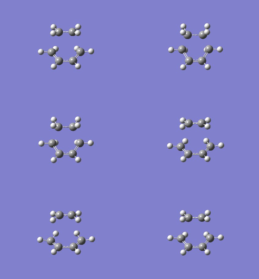
| ||
| Vibration Visualisation (Real) | 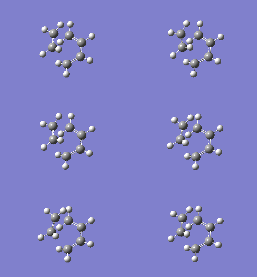
| ||
| Real Frequency/ cm-1 | 127 | ||
| C-C bond (terminal carbons)/ Å | 2.27 | ||
| C=C bond (carbons on ethylene)/ Å | 1.39 | ||
| C-C bonds on cis-butadiene)/ Å | 1.38 | ||
| C-C (sp3) Lit. / Å [3] [4] | 1.54 | ||
| C-C (sp3 - sp2) Lit. / Å [3] [4] | 1.50 | ||
| C=C (sp2) Lit. / Å [3] [4] | 1.47 |
The lowest real frequency shows tha the bond formation is asynchronous, however the imaginary frequency shows the opposite - the concerted formation. The bond lengths differ a little from the literature, but this is expected due to vibrations.
Next, the HOMO and LUMO were analysed.
Table 12: MO analysis of the Diels-Alder product
| Molecule | Molecular Orbital Visualisation | Energy/ Hartree | ||
| Cis-Butadiene+ethene TS | HOMO | 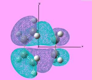 |
Symmetric | -0.361 |
| LUMO | 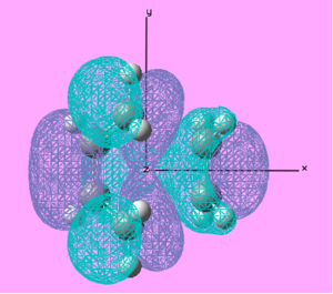 |
Anti-symmetric | 0.199 |
It can be seen that the previous expectations are confirmed. The HOMO of the transition state comes from the HOMO of cis-butadiene reactant and LUMO comes from ethylene reactant. The newly formed C-C σ orbitals can be seen with the same symmetry. The C-C σ* orbital can be observed to originate from the LUMO of the cis-butadiene LUMO and the HOMO of the ethylene HOMO.
Cyclohexa-1,3-diene + Maleic Anhydride reaction
Figure 6: Reaction of Cyclohexa-1,3-diene with maleic anhydride to give exo and endo products
In this reaction, two possible products are formed (exo and endo), so regioselectivity is to be determined. Since molecules involve carbonyls, it is expected there are interactions between π orbitals and possibly stabilise a transition state. As semi-empirical method AM1 with frozen coordinates turned out to give successful results, it was decided the same method is used on these calculations.
Table 13: Energy and Vibration analysis of the two products
| Endo TS | Exo TS | |||||
| Molecule | ||||||
| Energy/ Hartrees | -0.0531 | -0.0507 | ||||
| D-Space Link | DOI:10042/to-8187 | DOI:10042/to-8188 | ||||
| Imaginary Frequency/ cm-1 | -835 | -647 | ||||
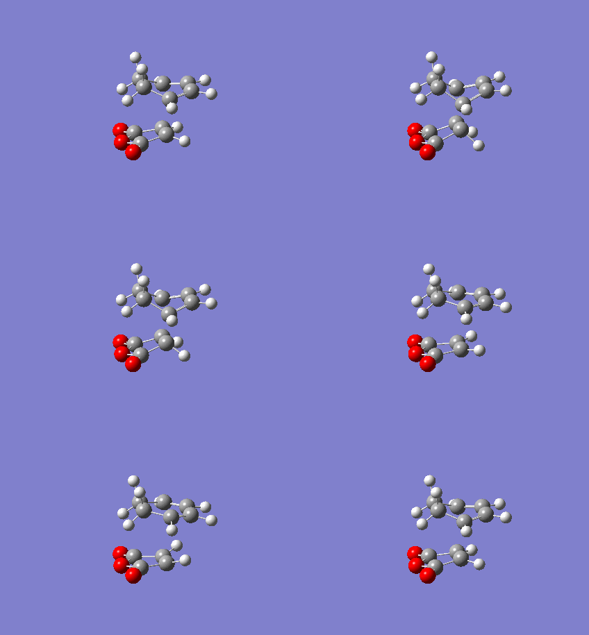
| Vibration visualisation | 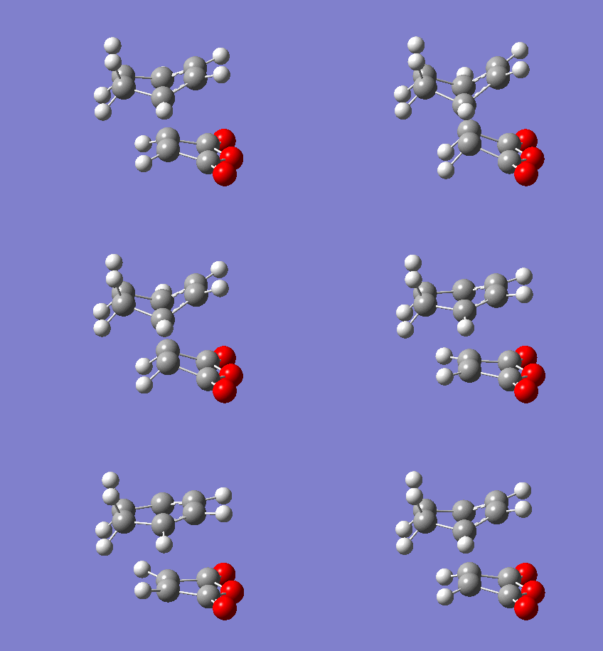 |
|
One would expect Exo TS to be more stable, due to strain in Endo TS (as C=O is closer to the ring by 0.02A. However this is not the case. It can be seen that the imaginary frequencies show the concerted bond formation. And we can see that the endo transition state was actually found to be of lowest energy. This is probably due to endo TS having interaction from C=O п orbitals that is stabilising the structure.
Table 14: MO analysis of the two products
| Molecule | Molecular Orbital | Molecular Orbital Visualisation | Energy/ Hartree | Symmetry |
| Endo TS | HOMO | 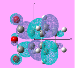 |
-0.348 | Anti-Symmetric |
| LUMO |  |
0.032 | Anti-Symmetric | |
| Exo TS | HOMO | 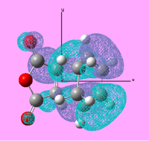 |
-0.339 | Anti-Symmetric |
| LUMO |  |
0.044 | Anti-Symmetric |
Conclusion
So far, we have been able to optimise and analyse reactants and products, but we did not know how to do that for transition states. That was the purpose of this Module, where different transition states were computed and analysed. It is interesting to see how an imaginary frequencies are visualised and to actually see where and how the bonds are breaking/forming. As in previous modules if an imaginary frequency was obtained, this was an indicator that the reaction did not reach the minimum and so calculations had to be redone. However as in TS case, we are supposed to get imaginary frequencies and so is more likely one makes mistakes, i.e. to think computer has calculated the correct TS. To avoid ambiguity, frozen method was introduced in order to "help" Gaussian reach the correct transition state. In general, it was found that DFT-B3LYP/6-31G(d) calculations give more accurate results than HF/3-21G, but this is expected since the latter is a lower level method. Overall it can be said that the calculations proceeded successfully and that the aims have been achieved - to investigate the performance of Gaussian even further and learn not only about reactant and products but also transition states, which are most of the time the main focus of Chemist's research.
References
- ↑ B.G. Rocque, J.M. Gonzales, H.F. Schaefer III, Mol. Phys., 2002, 100, 441 DOI:10.1080/00268970110081412
- ↑ G. Schultz, Istvfin Hargittai, Journal of Molecular Structure, 346, 15 February 1995, 63-69, DOI:10.1016/0022-2860(94)09007-C
- ↑ 3.0 3.1 3.2 Martinez-Guajardo G, Donald KJ et. al., Compresing C-C Single Bonds, Organic Letters, 2010
- ↑ 4.0 4.1 4.2 Fox M., Whitesell JK., Organische Chemie, 1994

