Rep:Mod 3: Celeste van den Bosch
Instructions: Module 3
See also: CvdB Mod:1, CvdB Mod:2
Please note that animations did not upload to the wiki page properly therefore it is sometimes necessary to click the image (twice) to view the animations.
Cope Rearrangement
The Cope rearrangement of 1,5-hexadiene can be investigated as an example of a chemical reactivity problem whose study using computational chemistry is of interest as one of the benefits of using computational methods is the opportunity to calculate (energies of) transition states which cannot be quantitatively studied in the laboratory.
 |
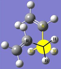
The Cope reaction is an example of a [3,3]-sigmatropic shift in which an allyl group migrates. This reaction has an electron count of 4n+2 (6 as seen by the arrows in fig.1) and is thermally allowed via a Hückel transition state. The investigation of this reaction will start with an optimisation of various structures of the reactants and products (which have the same structure) as well as the transition state which can adopt either a chair (fig.2) or boat conformation.
Reactants & Products
Optimisation
In GaussView 5.0 the structure of an anti linkage of 1,5-hexadiene was drawn and the structure 'cleaned' before being submitted to Gaussian for optimisation using the following script:
# opt hf/3-21g geom=connectivity
This direction states[1]:
- opt - short for optimisation; instructions to find a minimum energy geometry
- hf - abbreviation for Hartree-Fock; approximation method used to solve the Schrodinger equation
- 3-21g - low accuracy basis set for molecules constructed from light atoms[2]
- 3(g): basis function which is a combination of three Gaussian primitives
- 21: valence basis functions are split into 2 and 1 parts
- geom=connectivity - defines the source of molecule specifications (in this case position of atoms) as being specified for each atom following the initial script line
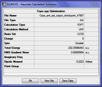
A crucial fact which appeared from the output summary (fig.3) was that a UHF method was used for this calculation. UHF is the Hartree-Fock method used for multiplets (anything above a singlet) while RHF is the method used for singlets.[3] As a singlet was expected, the input file was adjusted to correct this mistaken multiplicity and the file was resubmitted for optimisation using the script above with '0 1' (instead of '0 2') to indicate that this molecule has no charge and a multiplicity of one (i.e. singlet):
 # opt hf/3-21g geom=connectivity

0 1
 C                 -1.68454484   -0.34163429   -0.36923603
etc...
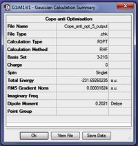
From the summary of this new output file (fig.4) it can be seen that the correct calculation method, namely RHF, has been used. Additionally, because the gradient is smaller than 0.001 it can be suggested that a minimum was found and that the energy of this minimum is -231.69260 a.u. The symmetry of this structure can be determined by enabling point group symmetry, and this was found to be C2.
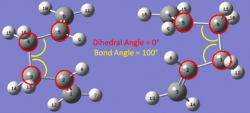
Due to steric repulsion, it was thought that this structure would be the most favourable and therefore have the lowest energy since the largest groups are as far apart as possible due to the anti linkage. To investigate this hypothesis, the above method was applied to other possible structures for the reactant/product in the Cope rearrangement of 1,5-hexadiene. Table 1 introduces the first two structures which were calculated and uses them to highlight the differences between antiperiplanar and gauche conformations:
| Conformer | anti | gauche |
| Newman Projection | 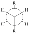 |
 |
| Annotated Image (from calculations) | 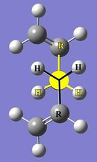 |
 |
Several other conformations were also investigated by running optimsation calculations and the results for these structures are summarized in Table 2 below. The structures were named by a comparison to provided literature; Appendix 1
| Conformer | Point Group | Energy/ Hartree | Jmol | D-Space Link |
| Anti 1 | C2 | -231.69260 |
|
DOI:10042/to-10016 |
| Anti 2 | Ci | -231.69254 |
|
DOI:10042/to-10014 |
| Gauche 1 | C2 | -231.68772 |
|
DOI:10042/to-10019 |
| Gauche 3 | C1 | -231.69266 |
|
DOI:10042/to-10015 |
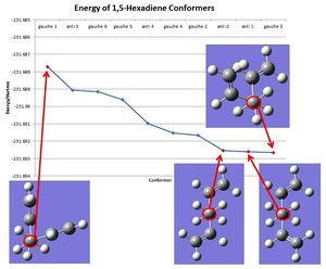
Using the data from Table 2 and augmented by data from Appendix 1 the different energies (as determined using the calculation method and basis set HF/3-21g) were compared (graph 1). From Graph 1 it can be seen that the conformer gauche 3 has the lowest energy and can therefore be considered the most stable conformer despite the prediction that lower steric repulsion in the conformer anti 1 would result in anti 1 having the lowest energy. Literature suggests that this unusual stability of gauche forms over anti conformations can be explained by an interaction between the alkene π orbital and the vinyl proton in 1,5-hexadiene.[4]
The conformer anti 2 was further optimised using a higher level method/basis set using the script:
# opt b3lyp/6-31g(d) geom=connectivity

0 1
 C                 -0.54397087   -0.17004155    0.52732770
 H                 -0.64956283   -1.24706919    0.60197899
 etc...
The new direction from this code are:
- b3lyp - a Density Functional Theory (DFT) method using Becke (B3) functions for exchange energies and Lee, Yang and Parr (LYP) for correlation energies[5]
- 6-31g(d) or 6-31G* - a higher level basis set developed by George Petersson and coworkers[1]
Note: The calculation was (mistakenly) initially run without (d) and a slightly higher energy of -234.55970 Hartree was found. This illustrated that it is crucial to include the (d) or * term to ensure that the shape of the conformer is fully optimised and the right structure is obtained.
Using the corrected calculation, the DFT structure of anti 2 was compared with the Hartree-Fock (HF) optimised structure and the findings were summarized in Table 3 below. Please note that generally bond lengths are considered accurate to 0.01Α however all available decimal places are presented in the table to illustrate the differences between the two calculations.
| Calculation Method | Energy/Hartree | Point Group | C-C bond length / Å | Central C-C bond length / Å | C=C bond length / Å | Dihedral angle(s) / ° | D-Space Link |
| HF/3-21g | -231.69254 | Ci | 1.50889 | 1.55308 | 1.31615 | 180° & 62° | DOI:10042/to-10014 |
| DFT/B3LYP/6-31g(d) | -234.61170 | Ci | 1.50419 | 1.54814 | 1.33352 | 180° & 64° | DOI:10042/to-10034 (6-31g:DOI:10042/to-10033 ) |
Overall it appears that at the normal degree of accuracy (to 0.01Å) the bond lengths are relatively similar. However the slight differences in the bond lengths suggest that the DFT method depicts a structure with greater delocalisation as, in the DFT structure, the single bonds are shorter and the double bonds are longer. Additionally it can be noted that because two different calculation methods were used, the calculated energies cannot be compared. If the calculation method is ignored and the two methods are compared it would be possible to conclude that the higher accuracy calculation (DFT) results in a more stable structure (perhaps because of greater delocalisation) and has a lower energy by 2.92 Hartrees.
Frequency Analysis
To check that the structure found for the conformer anti 2 is a minimum, a frequency analysis was carried out on the DFT optimised structure using the following code:
# freq rb3lyp/6-31g(d) geom=connectivity

0 1
 C                 -0.55939939   -0.17865986    0.50432180
 etc...
- freq - abbreviation for the instruction to run a frequency analysis
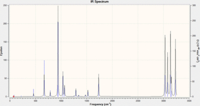
After running this calculation it was found that all frequencies were real and positive (Graph 2), indicating that a true minimum on the potential energy surface (PES) was found; a frequency analysis can be compared to taking a second derivative of the PES. Several additional values from this calculation are also of interest and these are shown below as an excerpt of the .log file (tabulated in Table 4):
 -------------------
 - Thermochemistry -
 -------------------
 Temperature   298.150 Kelvin.  Pressure   1.00000 Atm.
 Atom     1 has atomic number  6 and mass  12.00000
 Atom     2 has atomic number  1 and mass   1.00783
 ...
 Zero-point correction=                           0.142491 (Hartree/Particle)
 Thermal correction to Energy=                    0.149847
 Thermal correction to Enthalpy=                  0.150791
 Thermal correction to Gibbs Free Energy=         0.110882
 Sum of electronic and zero-point Energies=           -234.469212
 Sum of electronic and thermal Energies=              -234.461856
 Sum of electronic and thermal Enthalpies=            -234.460912
 Sum of electronic and thermal Free Energies=         -234.500821
The file was then edited to create a new input file to look at how these values are different at 0K. Initially this was run with the temperature set to 0.0 however this can (and did) cause issues during the calculation and resulted in the values for 298.15K being calculated again. In order to prevent this, the temperature was set to nearly zero (0.001K) instead.
# freq=readisotopes rb3lyp/6-31g(d) geom=connectivity

0 1
 C                 -0.55939900   -0.17866000    0.50432200
 etc ...

 0.0001 1.0
 12.0
 1.0
 etc...
The data from the two frequency calculations of anti 2 are summarized in Table 4 below:
| Energy Term | Value @ 298.15K | Value @ 0K | Description | Formula |
| Sum of electronic and zero-point energies | -234.469212 Hartrees | -234.468775 Hartrees | Potential energy at 0K taking zero-point vibrational energy into account | E=Eelec + ZPE |
| Sum of electronic and thermal energies | -234.461856 Hartrees | -234.468775 Hartrees | Energy at 298.15K and 1 atm, including translational, vibrational and rotational energy modes | E=E+Evib+Erot+Etrans |
| Sum of electronic and thermal enthalpies | -234.460912 Hartrees | -234.468775 Hartrees | Correction for RT | H=E + RT |
| Sum of electronic and thermal free energies | -234.500821 Hartrees | -234.468775 Hartrees | Contribution of entropy to free energy | G=H-TS |
| D-Space Link | DOI:10042/to-10034 | DOI:10042/to-10041 |
It is expected that the sum of electronic and zero-point energies is the same as the other values for this calculation as the temperature being run at is basically the zero-point, i.e. 0K. These values should therefore also correspond to the value for the 298.15K calculation for the sum of electronic and zero-point energies, -234.469212 Hartrees, and the difference between these two values is quite small. Additionally it can be noted that the value found when running the 0K calculation is smaller.
Transition Structures
Allyl Fragment
To start optimising the structure of the transition state, an allyl fragment was optimised to HF/3-21g. For this calculation, the allyl fragment is a doublet which was not initially recognised. Therefore the error message below was at the end of the first .log output file for this calculation.
 The combination of multiplicity 1 and 23 electrons is impossible.
 Error termination via Lnk1e in /apps/gaussian/g09
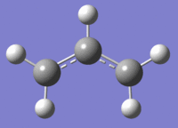
As a result the input file was edited to account for a multiplicity of two and resubmitted. The summary of this second calculation was:
| File Name | cope_allyl_2_opt_output_log_48634 |
| File Type | .log |
| Calculation Type | FOPT |
| Calculation Method | UHF |
| Basis Set | 3-21G |
| Charge | 0 |
| Spin | Doublet |
| E(UHF) | -115.8230401 |
| RMS Gradient Norm | 0.00002945 |
| Imaginary Freq | |
| Dipole Moment | 0.0292 |
| Point Group | CS |
| Job cpu time | 0 days 0 hours 0 minutes 17.0 seconds. |
| D-Space | DOI:10042/to-10165 |
Chair TS
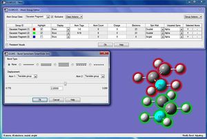
Two of the optimised allyl fragments were copied and pasted into a single file and then manipulated into an approximate chair structure with the distance between the terminal ends set to 2.20 Å (fig.6). Using a Hessian force constant matrix and this 'guess structure' it is possible to run an optimisation and frequency analysis. The following script was used for this:
# opt=(calcfc,ts,noeigen) freq hf/3-21g geom=connectivity
- calcfc - calculate the force constant once
- ts - the optimisation calculation is for a transition state (as opposed to a minimum); in this case a Berny transition state is being calculated
- noeigen - prevents the calculation from failing if the guess structure is not good enough (i.e. if more than one imaginary frequency is calculated)
The output summary for this calculation is shown in Table 6 below:
| File Name | cope_ts_chair_Hessian_opt+freq_log_48647 |
| File Type | .log |
| Calculation Type | FREQ |
| Calculation Method | RHF |
| Basis Set | 3-21G |
| Charge | 0 |
| Spin | Singlet |
| E(RHF) | -231.6193224 |
| RMS Gradient Norm | 0.00003049 |
| Imaginary Freq | 1 |
| Dipole Moment | 0.0006 |
| Point Group | C1 |
| Job cpu time | 0 days 0 hours 0 minutes 17.0 seconds |
| D-Space Link | DOI:10042/to-10166 |
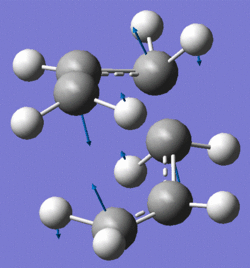
The frequency analysis from this calculation shows that there is an imaginary frequency at -818cm-1 which corresponds to the Cope rearrangement (fig.7). In a comparison to literature, it can be noted that the energy of -231.619322 Hartrees corresponds to the value given in Appendix 2. A negative frequency value corresponds to a negative outcome for the second derivative of the PES and therefore to a maximum. As a result whenever an imaginary frequency value is found it can be stated that the calculation is referring to a transition state as these occur as maxima on PES.

A second way to determine the optimised transition state structure is the frozen coordinate method. In order to do this the "bonds" between the terminal carbons of the allyl fragments are frozen (fig.8). The input for this calculation is:
# opt=modredundant hf/3-21g geom=connectivity

0 1
 C                  0.91545446    1.63274708   -0.01415498
 etc...

B 3 11 2.200000 F
B 6 14 2.200000 F
- 'modredundant - refers to the freezing (F) of the two bonds (B) which is noted at the bottom of the input file. With these frozen bonds it it possible to calculate this first step as a minimum.
The formatted checkpoint file can then be further optimised by removing the freezing of bond distance to 2.2Å. Alternatively the redundant coordinate editor is employed to set a bond between the terminal carbons of the alkyll fragments to 'derivative' (D). The new calculation input is set up to calculate a transition state (Berny):
# opt=(ts,modredundant) rhf/3-21g geom=connectivity

0 1
 C                 -1.44029251    0.00016231    0.30497433
 etc...

B 3 11 D
B 6 14 D
The results from these two different methods for calculating the structure of the chair transition state in the Cope rearrangement are summarized in Table 7 below:

| Method | Hessian | Frozen Coord |
| Jmol | ||
| Calculation Type | FREQ | FTS |
| Calculation Method | RHF | RHF |
| Basis Set | 3-21G | 3-21G |
| E(RHF) | -231.619322 | -231.619322 |
| Imaginary Frequency / cm-1 | -818 | -818 |
| Alkyl connection length (between terminal carbons) / Å | 2.02 | 2.02 |
| Terminal C-H bond length / Å | 1.08 | 1.08 |
| Central C-H bond length / Å | 1.08 | 1.08 |
| C-C bond length / Å | 1.39 | 1.39 |
| C-C-C bond angle / ° | 121 | 121 |
| D-Space Link | DOI:10042/to-10166 | DOI:10042/to-10169 File:Cope ts chair unfreeze coord opt+freq output.out |
As noted in Table 7, both structures have an imaginary frequency (fig.7 and animation 1) which again suggests that both methods have succeeded in calculating transition states. Further from this table it can be seen that within the scope of accuracy for these types of calculations the two structures are identical as differences in bond lengths only occur in the fourth decimal place.
Boat TS
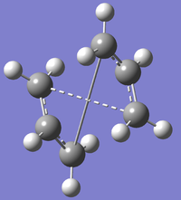
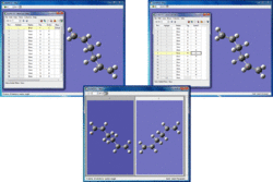
In order to investigate the boat transition state the QST2 method was used. To use this method the reactants and products are specified and the transition state between these two is found. Therefore it is important that the numberings of the products and reactants match up (fig.10). These two structures and then submitted as one input file using the following script:
# opt=qst2 freq hf/3-21g geom=connectivity

Cope Boat TS Opt+Freq

0 1
 C                  2.99807633    0.22509803    0.13520931
 etc...

Cope Boat TS Opt+Freq

0 1
 C                 -0.55939939   -0.17865986    0.50432180
 etc...
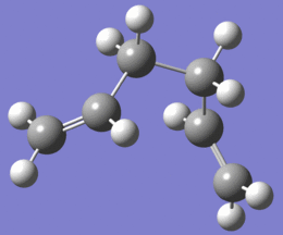
This initial optimisation failed (fig.9) as the output looked like a dissociated chair transition state as opposed to the boat transition state which is the goal of this calculation.
Therefore the structures were manually edited (fig.11) with a central C-C-C-C dihedral angle of 0° (versus 180°) and two 'central' C-C-C bond angles of 100° (versus 113°). The summary of this calculation is tabulated in Table 8:

| File Type | .fch |
| Calculation Type | FREQ |
| Calculation Method | RHF |
| Basis Set | 3-21G |
| Charge | 0 |
| Spin | Singlet |
| Total Energy | -231.6028022 |
| RMS Gradient Norm | 0.00008186 |
| Dipole Moment | 0.1577 |
| D-Space Link | DOI:10042/to-10171 |
As for the chair transition state, an imaginary frequency (animation 2) was found, again confirming that the structure is a transition state. The energy of this TS is slightly higher than that for the boat, by 0.0165 Hartrees, confirming that the chair is the more stable TS.
Intrinsic Reaction Coordinate
The intrinsic reaction coordinate (IRC) is a method in Gaussian which allows a minimum energy path to be followed from a transition structure to its local minimum along a potential energy surface (PES) by making slight changes to the structure and then determining where the gradient of the PES is the steepest. This can be used to determine which structure the chair and boat transition states lead to.
Using the output formatted checkpoint file from the Hessian chair transition state calculation, a new calculation was run to determine the IRC using the script:
# irc=(forward,maxpoints=50,calcfc) rhf/3-21g geom=connectivity

0 1
 C                 -1.41256083    0.00007345   -0.27758994
etc...
- forward - direction of calculation (could be forward, backward or both). As a reversible reaction the forward and backward paths are expected to be equal and opposite.
- maxpoints=50 - number of points along the IRC is set to calculate 50
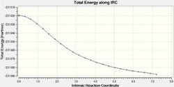
From the output of this initial IRC analysis where the force constant has been calculated only once, it can be seen that this calculation has not reached a minimum. The number of steps was set to 50 for this calculation however there are 24 steps (animation 3, Table 10) showing intermediate geometries in the output file suggesting that the it would not be beneficial to reach a minimum by running the calculation with a greater number of steps.
To more accurately calculate the end result of the path being followed by this calculation, a minimum can be reached by submitting the last step/intermediate of the IRC for an optimisation. Table 9 illustrates the difference between the unoptimised and the optimised final step of the initial IRC calculation:
 |
 |
| DOI:10042/to-10177 | DOI:10042/to-10178 |
| -231.68811 Hartrees | -231.69167 Hartrees |
The energy of the optimised step 24 (fig.13) corresponds to the structure gauche 2 (from Appendix 1)and therefore from Table 9 it can be concluded that the minimum energy path of the chair TS leads to the formation of the gauche 2 conformation.
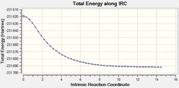
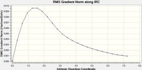
An additional method of more accurately calculating the IRC is to determine the force constant at every point. This was done by changing the original script from calcfc to calcall. The differences between these two calculations can be visualised in Table 10:
| One Force Constant | All Force Constants |
| DOI:10042/to-10177 | DOI:10042/to-10179 |
 |
 |
 |
 |
 |
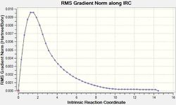 |
From Table 10 it can be seen that when the IRC was initially run with the force constant being calculated once (at the beginning of the calculation) the curve does not reach a minimum as it does not level off at the end. However when the force constant was calculated for each step, it can be seen from both the shape of both the gradient and total energy graphs that a minimum was found.
The three IRC structures can be compared along with the the structure of the chair transition state with the results of this comparison presented in Table 11:
| Structure | Chair TS (Hessian) | IRC 1 (structure 24) | Step 24 Opt | IRC 2 (structure 47) |
| Energy / Hartree | -231.619322 | -231.68811 | -231.69167 | -231.69166 |
| Alkyl connection length (between terminal carbons) / Å | 2.02 | 1.56 & 3.28 (both not bonding) | 1.55 (bonding) & 4.39 (not bonding) | 1.55 (bonding) & 4.36 (not bonding) |
| Terminal C-H bond length / Å | 1.08 | 1.07 & 1.08 | 1.07 | 1.07 |
| Central C-H bond length / Å | 1.08 | 1.08 | 1.08 | 1.08 |
| C-C bond length (non-terminal carbons) / Å | 1.39 | 1.32 & 1.51 | 1.32 (double bond) & 1.51 (single bond) | 1.32 (double bond) & 1.51 (single bond) |
| C-C-C bond angle / Å | 121 | 124 | 125 | 125 |
| C-C-C-C dihedral angle / Å | n.a. | n.a. | 64 | 65 |
From this data it can be concluded that there are only slight differences between the three end points which were found. As expected, all three also clearly resemble the product to a much greater extent than the transition state. However the difference in accuracy between the methods can be observed by the energy. The first method of only calculating the force constant once did not provide a good minimum while the two other methods; optimising the final step of this initial IRC calculation and calculating the IRC a second time with force constants being determined at every point, both suggest that the likely reactant/product (because of the suggested symmetrical nature of the forward and backward reactions) is gauche 2 (energy = -231.69167 Hartrees).
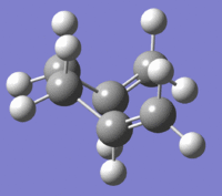
The same can be done for the boat transition state and the results for this are summarized in Table 12 below:
| Structure | Boat TS | IRC 1 (structure 20) | Step 20 Opt | IRC 2 (structure 47) |
| Visualisation | 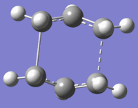 |
 |
 |
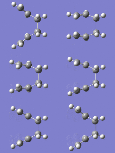 |
| Output File | File:Cope ts boat checkpoint.fchk File:COPE TS BOAT IRC 1.LOG | File:COPE TS BOAT IRC 1.LOG | File:COPE TS BOAT IRC STEP20 OPT.LOG | File:Cope ts boat irc 2 output.out |
| Energy / Hartree | -231.60280 | -231.67203 | -231.68303 (Cs point group) | -231.68303 (C1 point group) |
| C-C (terminal) bond length / Å | 2.14 (both showing bond) | 1.59 (bond) & 3.01 (no bond) | 1.58 (bond) & 4.35 (no bond) | 1.58 (bond) & 4.34 (no bond) |
| C-C bond length / Å | 1.38 | 1.51 | 1.51 | 1.51 |
| C=C bond length / Å | 1.38 | 1.31 | 1.32 | 1.32 |
| C-C-C bond angle / ° | 122 | 113 | 124 | 124 |
| C-C-C-C dihedral angle / ° | 0 | 0 | 0 | 0(.12531) |
Activation Energy
The chair and boat HF optimisationed TS were reoptimised using the more accurate basis set DFT/B3LYPT/6-31G(d). Using the thermochemistry data, Table 13 was constructed to compare the energies for the boat and chair of the two different calculation methods and also to calculate the activation energy using the data from the reactant (anti 2) as the activation energy is calculated from the lowest energy reactant to the transition state.
| Structure | Chair TS | Chair TS | Boat TS | Boat TS | Anti 2 Conformer | Anti 2 Conformer |
| Output File | File:Cope ts chair Hessian opt+freq log 48647.out | File:COPE CHAIR REOPTIMISED DFT OPT+FREQ.LOG | File:Cope ts boat opt+freq 2 output log 48687.out | File:Cope ts boat opt+freq dft output.out | File:Cope anti 2 opt+freq output.out | DOI:10042/10034 |
| Calculation Method | HF | DFT | HF | DFT | HF | DFT |
| Basis Set | 3-21G | B3LYP/6-31G(d) | 3-21G | B3LYP/6-31G(d) | 3-21G | B3LYP/6-31G(d) |
| Total Energy / Hartree | -231.61932 | -231.60280 | -234.54309 | -231.69254 | -234.61170 | |
| Sum of electronic and zero-point Energies | -231.466699 | -234.414932 | -231.450932 | -234.40234 | -231.53954 | -234.469212 |
| Sum of electronic and thermal Energies | -231.46134 | -234.409011 | -231.445305 | -234.396006 | -231.532566 | -234.461856 |
| Sum of electronic and thermal Enthalpies | -231.460396 | -234.408067 | -231.444361 | -234.395061 | -231.531622 | -234.460912 |
| Sum of electronic and thermal Free Energies | -231.495205 | -234.443817 | -231.47912 | -234.431097 | -231.570914 | -234.500821 |
| Activation Energy @ 0K / Hartree | 0.072841 | 0.05428 | 0.088608 | 0.06687 | . | . |
| Activation Energy @ 0K / kcal mol-1 | 45.71 | 34.06 | 55.60 | 41.96 | . | . |
| Activation Energy @ 298.15K / Hartree | 0.071226 | 0.05285 | 0.087261 | 0.06585 | . | . |
| Activation Energy @ 298.15K / kcal mol-1 | 44.69 | 33.16 | 54.76 | 41.32 | . | . |
The experimental data shows that the activation energies are 33.5 ± 0.5 kcal/mol and 44.7 ± 2.0 kcal/mol via the chair and boat transition structure respectively. Therefore it can be suggested that reoptimisation using a higher level theory is beneficial as the data for the B3LYP/6-31G(d) resulted in data which was a reasonable match for experimental data.
Conclusion
In this investigation of the Cope rearrangement the aim was to use various methods in order to locate the transition structures on the PES of a rearrangement of 1,5-hexadiene. This was accomplished by optimising and comparing several different conformations of 1,5-hexadiene and then using the most stable (anti 2)[6] to compare to two transition states, chair and boat which were optimised using three different methods (Hessian, frozen coord and QST2). From this it was found that the chair is the more stable transition state and that when the forward (equivalent to the backward) process is calculated using IRD the chair leads to the gauche 2 structure. Further when comparing activation energies, it was found that using the more accurate DFT/B3LYP method the results were correspondingly closer to experimental values.
Diels-Alder Reaction

The Diels-Alder reaction is a pericyclic reaction which takes place between a diene and a dienophile. During the reaction 2π bonds are broken and two σ bonds take their place. It has been suggested in literature that the stability of the transition state is due to the presence of six delocalised electrons resulting in aromatic character. There are two possible outcomes for the Diels-Alder reaction, either the exo or the endo product. The exo product is considered to be more stable and is therefore formed in a reversible reaction under thermodynamic conditions. The reason for this stability is thought to be the interactions between the HOMO of the diene and the LUMO of the dienophile (fig.15) as it has been suggested that in the endo form the p-orbitals are orientated with the correct symmetry and overlap to be able to stabilise and aid the formation of the endo product.[7] In this investigation two Diels-Alder reactions; namely the reaction of ethene and cis-butadiene and the reaction of cyclohexadiene and maleic anhydride, will be considered in terms of their transition states and molecular orbitals (MOs).
cis-Butadiene
Using GaussView 5.0 a molecule of cis butadiene was constructed and entered into Gaussian 09 using the script:
# opt am1 geom=connectivity
However this command line came back with the error:
Route card not found.
 Error termination via Lnk1e in /apps/gaussian/g09
It was attempted to also optimise this structure using both the lower level HF/3-21g(d) and the higher level DFT/B3LYP/3-21g(d). However in all cases the .log file returned with the above error. As all three of these calculations were run on SCAN and received the same error message, it was determined that there was a problem with SCAN (results could also not be published to D-Space and jobs remaining pending or coming back within a second) therefore the original calculation using the semi-empirical AM1 was successfully run on the desktop computer. A minimum had been found as can be determined as the gradient in the summary file is smaller than 0.001. Additionally, from an excerpt of the .log file where it is noted that all the calculations converged and therefore it could be concluded that a stationary point was found:
       Item               Value     Threshold  Converged?
 Maximum Force            0.000018     0.000450     YES
 RMS     Force            0.000004     0.000300     YES
 Maximum Displacement     0.001423     0.001800     YES
 RMS     Displacement     0.000562     0.001200     YES
 Predicted change in Energy=-2.318264D-09
 Optimization completed.
    -- Stationary point found.
To view the molecular orbitals (MOs) of this fragment the AM1 optimised structure was submitted again with the script:
# am1 pop=(full) geom=connectivity
In this case energy is being calculated and pop=(full) refers to all the molecular orbitals which are to be calculated being populated(method used for Module 2). On viewing the MOs this it can be seen that both the HOMO and LUMO are asymmetric about the plane of the molecule. The HOMO is also asymmetric about plane perpendicular to the molecule while the LUMO is symmetrical with respect to the perpendicular plane (σv). This is summarized in Table 14:
| . | HOMO | LUMO |
| cis-Butadiene File:DA CISBUTADIENE OPT AM1 MO 2.LOG | 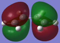 |
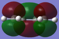
|
| σv symmetry | asymmetric | symmetric |
| Ethene File:DA ALKENE OPT MO.LOG | 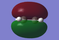 |

|
| σv symmetry | symmetric | asymmetric |
From this table it can be concluded that due to the fact that only orbitals of the same symmetry can interact, the reaction of cis-butadiene with ethene will proceed via the HOMO of butadiene with the LUMO of ethene (or possibly vice versa).
Transition State
The frozen coordinate method was used. To that end, an input file was created using an optimised structure of cis-butadiene and ethene with frozen coordinates following the script:
# opt=modredundant am1 geom=connectivity

0 1

 C(Fragment=1)      3.03242830   -2.13138072    0.06250280
 ...

B 4 14 2.000000 F
B 1 7 2.000000 F
Once returned the checkpoint file from this was then edited so that the bonds were no longer frozen (instead set to derivative). The file did not work on repeated attempts using AM1 therefore the file was run using Hartree-Fock with a 3-21G basis set. This calculation did result in an imaginary frequency (-818 cm-1) and therefore confirmed that a transition state had been found. For comparison, the file was submitted again using the semi-empirical AM1 method and was successfully run, again confirming that a transition state was found as there was an imaginary frequency at -958cm-1.
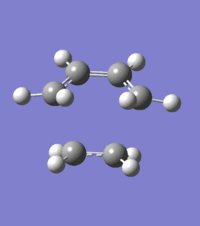
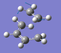
The two lowest frequencies, imaginary and lowest positive (animation 7 and animation 8 - File:DA TS 1 OPT FREEZECOORD AM1 P2 3.chk), can be compared. The imaginary frequency shows that the Diels-Alder reaction path is synchronous as the two bonds are being formed/broken simultaneously. This appears to be in contrast to the lowest positive frequency which is asynchronous with the two bonds in question forming/breaking alternatively.
Diels-Alder Transition State |
The bond lengths in this transition state have been summarized in Table 15:
| C=C bond length / Å | 1.38 (ethene) & 1.40 (butadiene) |
| C-H bond length / Å | 1.10 |
| C-C bond length / Å | 1.38 |
| (C=)C-H bond length / Å | 1.10 |
| C-H(=C) bond length / Å | 1.10 |
| Forming σ C-C bond length / Å | 2.12 |
These values can be compared to literature[8] values for typical sp3 and sp2 C-C bond lengths which are approximately 1.54 and 1.49 Å respectively. Overall the C-C bonds in the transition state are shorter than expected. Additionally, while the σ C-C bond is forming in the transition state it is still quite a length away from what is expected in the product. In particular it is important to note that this length is longer than a normal C-C bond but shorter than twice the van der Waal's radius for carbon (1.70 Å). This proves that the structure found is a transition state as a C-C bond has not been formed, but the two carbon atoms are interacting.
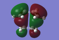
Further the HOMO and LUMO molecular orbitals were generated (File:DA TS 1 OPT FREEZECOORD AM1 P2 3 MO.LOG):
 |
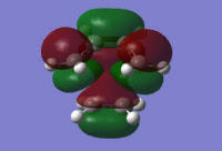 |
From the MOs, it can be determined that the HOMO is asymmetric (fig.16) and the LUMO is symmetric (fig.17) in the transition state. Therefore it can be suggested that the HOMO was formed from a linear combination of the asymmetric cis-butadiene HOMO and ethene LUMO while the transition state LUMO was formed from a linear combination of the symmetric cis-butadiene LUMO and ethene HOMO.
Regioselectivity
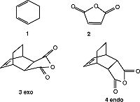
To study the regioselectivity of the Diels-Alder, a second reaction was studied, namely that of the reaction of maleic anhydride (2) with cyclohexa-1,3-diene (1). From fig.18 it can be seen that this reaction can form either the exo (3) or endo (4) product. As stated in the introduction, the exo product should be higher in energy as the endo product is the thermodynamic product. In order to test this, the transition structures were constructed and compared.
Initially the QST2 method was attempted in attempts to create a good model for the transition state of the endo product, however it was found that in order to use this method it is imperative that a good guess structure is entered. As the symmetry was slightly off, the transition state was not found using this method. The input for one of these calculations: File:DA2 endo numbering 4.gjf and the corresponding output: File:DA2 ENDO AM1QST2 OPT 4.LOG. Though the numbering was set up to correspond between the product and reactant often these calculations returned with very odd bonds (for instance multiple bonds to hydrogen).
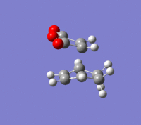
Therefore the calculation method was changed and instead a freeze coordinate method was used to calculate the transition states of the HOMO and LUMO and the results are summarized in Table 16. From basic chemistry knowledge it would be suggested that the exo transition state leads to the more stable product as there is less steric repulsion. However, from a more detailed chemical understanding, it is known that this is not the case and the endo product is favoured. This is confirmed by the difference in energy, shown in Table 16, as the endo transition state has a greater stabilising energy. This can be explained by secondary orbital overlap. As shown in fig.15 the endo structure has a greater stabilisation due to secondary orbitals. Conversely the exo transition state is less stabilised as it does not have these secondary orbital interactions. Therefore it can be concluded that this reaction proceeds according to the endo rule.[7]
| TS | Endo | Exo |
| Output File | File:DA2 ENDO AM1 UNFREEZE NEW OPT 1.LOG | File:DA2 EXO AM1 UNFREEZE OPT 1.LOG |
| Total Energy / Hartrees | -0.05150 | -0.05042 |
| Imaginary frequency / cm-1 | 806 | 812 |
| . |  |
 |
| Bond forming length / Å | 2.16 | 2.17 |
| C-C bond length / Å | 1.49 & 1.52 | 1.49 & 1.53 |
| C=C bond length / Å | 1.40 (diene) & 1.41 (MA) | 1.40 (diene) & 1.41 (MA) |
| C=O bond length / Å | 1.22 | 1.22 |
| C-O bond length / Å | 1.41 | 1.41 |
| Jmol | ||
| LUMO |  |
 |
| HOMO | 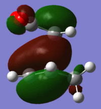 |
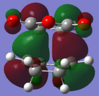 |
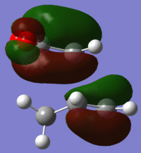
In terms of MOs it can be seen that there is little difference to be seen between the two transition states suggesting that the calculation method used was not able to take secondary orbital interactions into account. Additionally it can be noted that they are all asymmetric. From this table it can first be stated that transition states were found as an imaginary frequency was found for both. The vibrations as can be viewed for the imaginary frequency show that this Diels-Alder reaction occurs in a concerted fashion and can therefore be classified as a synchronous bond formation.
Conclusion
In looking at the Diels-Alder reaction using computational chemistry it was found that the transition states can be accurately modelled and MOs generated to determine symmetry (and therefore allowed and forbidden reaction). However, when attempting to determine the source of the stability of the endo product it was found that the expected secondary orbital interactions were not visible. Therefore it can be suggested that it would be beneficial to recalculate at a different (higher) level. In addition it would be interesting to try different Diels-Alder reactions where substituted rings [9] are compared to prove (or disprove) the secondary orbital interactions theory and also to investigate the lowest energy position(s) for the substituents in the final product.
References
- ↑ 1.0 1.1 Gaussian 09 User's Reference
- ↑ Self-consistent Molecular-Orbital Methods. 22. Small Split-Valence Basis Sets for Second-Row Elements DOI:10.1021/ja00374a017
- ↑ The Absolute Beginners Guide to Gaussian
- ↑ Conformational Study of 1,5-Hexadiene and 1,5-Diene-3,4-diols DOI:10.1021/ja00111a016
- ↑ Density Functional Theory Isotope Effects and Activation Energies for the Cope and Claisen Rearrangements DOI:10.1021/ja00101a078
- ↑ Cope Rearrangement of 1,5-Hexadiene: Full Geometry Optimizations Using Analytic MR-CISD and MR-AQCC Gradient Methods DOI:10.1021/jp0259014
- ↑ 7.0 7.1 Clayden, Greeves, Warren and Wothers. "Organic Chemistry", Oxford University Press, 7th edition, 2008, pp. 905-916.
- ↑ Online CRC Handbook of Chemistry and Physics, 92nd edition, 2012
- ↑ Computational and Experimental Investigation of the Diels-Alder Cycloadditions of 4-Chloro-2(H)-pyran-2-one DOI:10.1021/jo0348827

