Rep:Mod:xz926
Introduction
Based on Born Oppenheimer approximation, the energy minimum structure of a molecule can be located on the potential energy surface (PES) generated by doing single point calculations and plotting all the possible structures.
The Cope Rearrangement (tutorial)
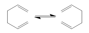
In this tutorial, the reaction pathway of Cope rearrangement of 1,5-hexadiene was studied. This reaction is a 3-3' sigma tropic rearrangement that obeys the Wardwood Hoffmann Rules, which state that for a thermally allowed pericyclic reaction, the total number of (4q+2)s and (4r)a components must be odd.
The total energy of the reactant/product was investigated and two possible transition structures, chair and boat, were located on the potential energy surface (PES) using various methods. The activation energies for both structures were calculated and compared with the experimental values. All of the calculations were done by GaussView 5.0.
Optimizing the Reactants and Products
Optimizing the 'anti' and 'gauche' 1,5-hexadiene
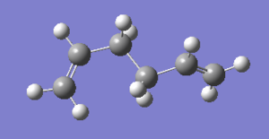
A 1,5-hexadiene molecule with anti linkage was drawn and optimized to minimum using HF/3-21G level of theory. After the job has finished, check file was opened and the Total Energy was record in summary under Results. The energy is -231.69097054 a.u.. The molecule has a symmetry and the point group is C1. This conformer is the anti4 in the Appendix 1. [1]
The total energy of the 'gauche' conformer is expected to be higher than 'anti' because of steric hindrance between the two π systems. A 1,5-hexadiene molecule with anti linkage was drawn and optimized to minimun using same level of theory. The Total Energy of the molecule is -231.69266121 a.u., which is lower than the optimized 'anti' conformer. This result was different from the expectation. The molecule has a symmetry and the point group is C1. This conformer is the gauche3 in the Appendix 1. [2]

Finding the lowest energy conformer
The lowest energy conformer of 1,5-hexadiene was expected to be the anti2 since the vinyl group are farthest away from each other. However this was not the case for 1,5-hexadiene. The difference of distance between two vinyl hydrogen atoms in 'anti' and 'gauche' forms is very small. Therefore the steric effect is not significant. The gauche3 structure that has already been drawn and optimized in the last step is the lowest conformer of 1,5-hexadiene.[3] This is because there is attractive interaction between the C=C double bond and the vinyl proton. The filled π orbital can donating electron density to the empty σ* orbital and stablise the molecule.[1]
(Re)optimizing the anti2 conformer
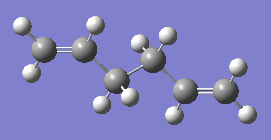
An anti2 1,5-hexadiene molecule was drawn and optimized using HF/3-21G level of method. The molecule has a symmetry and the point group is Ci. The Total Energy of the molecule is -231.69253528 a.u. and the reference value given in the table in Appendix 1 is -231.69254 a.u..[4] They are almost the same. So the structure has been drawn correctly. The HF/3-21G optimized anti2 1,5-hexadiene molecule was reoptimized by B3LYP/6-31G* level of theory. The overall geometry changed very little from the previous HF/3-21G optimized structure. However, the total energy of the B3LYP/6-31G* optimised structure is lower than the HF/3-21G optimized structure.
Frequency calculation on anti2 conformer
For the comparison of the final total energies of the output file and the experimental values, frequency calculation needs to be run. The B3LYP/6-31G* optimized anti2 1,5-hexadiene molecule was performed a frequency calculation and all the vibrational frequencies were positive (i.e. no imaginary frequencies). From the .log output file viewed in the visualizer, energies under different vibrational temperatures were noted down.
| sum of energies | in a.u. | in kcal/mol |
|---|---|---|
| electronic and zero-point energies | -234.469212 | -147131.683317 |
| electronic and thermal energies | -234.461856 | -147127.067357 |
| electronic and thermal enthalpies | -234.460912 | -147126.474988 |
| electronic and thermal free energies | -234.500821 | -147151.518269 |
Optimizing the 'Chair' and 'Boat' Transition Structures
It was proposed that the Cope rearrangement reaction can take place via two different transition states, chair and boat. Both transition state were optimized but with different methods.
Optimizing the 'Chair' transition structure (method 1)
The 'Chair' transition structure was located and optimized using the method of calculating the force constant. Two identical allyl fragments were drawn and optimized using the HF/3-21G level of theory. They were moved into an orientation that was close to the 'chair' transition structure with a distance of approximately 2.2 Å apart. Opt+Freq calculations were carried out with optimisation to TS (Berny) and calculate the force constant once. Opt=NoEigen was put in as additional keywords. The output molecule had only one negative vibration frequencies at -817.90 cm-1 and the rest were positive frequencies. The animation of this imaginary frequency was identified to be the Cope rearrangement as shown below. The RMS Gradient Norm of the molecule was 0.00001426 a.u., which was almost zero. IRC All of these factors indicated that it was the correct transition state of the reaction.
ANIMATION ADDED
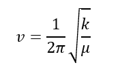
The imaginary frequency represents a negative force constant k. Since for a 1D quantum harmonic oscillator, k is the second derivative of the energy (i.e. curvature). It would be negative at the energy maxima, where a transition state is on the potential energy surface. Therefore the vibrational frequency would be negative from the equation below.
Optimizing the 'Chair' transition structure (method 2)
The 'Chair' transition structure was optimized using the frozen coordinate method. Redundant Coord Editor was used to freeze the four carbon atoms that form/break bonds respectively and left the rest of the molecule free for minimisation. Here optimization to minimum was operated instead of optimization to TS (Berny). Force constant was not calculated. The output molecule showed a fixed distance of 2.2 Å between the bond form/break carbon atoms. Redundant Coord Editor was used again to unfreeze the carbon atoms and this time optimized to TS (Berny). Force constant was not calculated. The output molecule had only one negative vibration frequencies at -817.88 cm-1 and the rest were positive frequencies. The animation of this imaginary frequency was identified to be the Cope rearrangement as shown below. The RMS Gradient Norm of the molecule was 0.00002117 a.u., which was almost zero. IRC All of these factors indicated that it was the correct transition state of the reaction.
ANIMATION ADDED
The bond form/break bond lengths of the transition structures generated by the two methods were very similar with the one from method 2 slightly higher.
| Bond break/form C-C bond lengths (Å) | |
|---|---|
| method 1 | 2.02064 |
| method 2 | 2.02071 |
Optimizing the 'Boat' transition structure
The 'Boat' transition structure was located and optimized using the TS(QST2) method. In this method, the reactant and product were drawn out and given the same number to each atom. The calculation can work out the transition structure based on the numbering and orientation of the reactants and products. The HF/6-31G optimized anti2 1,5-hexadiene were used as both reactant and product and the two molecules were modified as below. It illustrated that from reactant to product the bond between C3 and C4 broke and between C1 and C6 formed. The double bond moved from between C1,C2 and C5,C6 to C2,C3 and C4,C5. The input molecules looked like this.
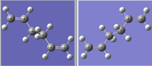
However in this case, the job failed. The TS(QTS2) method was not able to locate the correct transition state from this arrangement of reactant and product because it is too deviated from the actual boat transition state structure. So the input molecules were modified by changing the central C-C-C-C dihedral angle to 100° and the inside C-C-C angle to 100°. The numbering of each atom was kept unchanged. The molecules now looked like this.
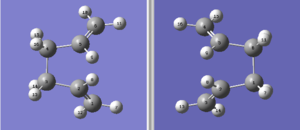
This time the input molecule were close enough to the boat transition structure and it was successfully located. Again a negative frequency was shown at and the corresponding animation (below) indicated the Cope rearrangement reaction.
ANIMATION ADDED
This exercise showed that although the TS (QTS2) method was able to directly calculated the transition structure from just the reactant and product, it was only valid when the input reactant and product were modified in a way very close to the actual structure of the desired transition state. Otherwise the transition state could not be achieved.
Intrinsic reaction coordinate (IRC) method
Now the boat and chair transition structures were found out successfully. The conformer of 1,5-hexadiene that each transition structures connect to was difficult to predict. The IRC method were used to locate the locate minimum from the transition structure on the potential energy surface. This method was applied to the optimized chair transition structure. For calculation set up, only forward direction was chosen because the reaction coordinate was symmetrical. The reactant and product should have the same structure and therefore the same energy. Force constant calculation was chosen to be always and the points generated along the IRC path was set to be 50. The results were as shown below.
ANIMATION ADDED

It was realised that the chair transition structure connected to the gauche linkage of 1,5-hexadiene. Both the total energy in summary and the IRC plot showed that the minimum energy geometry had not been reached. (The total energy of gauche3 conformer is -231.69266 a.u.).[5] Therefore IRC method was improved to locate a further minimized structure. The last point on IRC plot, which was the minimum from last calculation, was taken to run a normal minimisation. The output geometry had a lower total energy than the input as shown in the table. Other possible improvement methods include increasing of the point on the IRC path and calculating the force constant on every step.
| total energy in a.u. | |
|---|---|
| input geometry | -231.69158 |
| output geometry | -231.69167 |
Activation energies
To activation energies of the reaction for both chair and boat transition structures, both chair and boat transition structures were reoptimized using B3LYP/6-31G* level of theory using the previously HF/3-21G optimized structures. As a result, the geometries of reactant and transition structure were very similar for each level of theory,showing that 3-21G basis set was good enough to get the correct geometry of the transition structure. However the total energy difference was large. The activation energies were calculated at 0K and 298.15K from the raw data (in a.u.) collected in the .log file for both transition structures and compared to the experimental values. [6]
| HF/3-21G | HF/3-21G | B3LYP/6-31G* | B3LYP/6.31G* | Experimental values | |
|---|---|---|---|---|---|
| at 0 K | at 298.15 K | at 0 K | at 298.15 K | at 0 K | |
| ΔE in kcal/mol (Chair TS) | 38.4 | 37.3 | 34.1 | 33.2 | 33.5 ± 0.5 |
| ΔE in kcal/mol (Boat TS) | 48.2 | 47.4 | 42.0 | 41.3 | 44.7 ± 2.0 |
The comparison of results showed that the activation energies calculated from B3LYP/6-31G* is closer to the experimental values the ones from HF/3-21G. The values were almost in the range of the experimental data. This indicated that the Density Functional Theory (DFT) method was more accurate than the Hartree Fock (HF) method. This is because the DFT method includes the exchange-correlation term, which shows the correction to the kinetic energy due to interacting nature of electrons, as well as all of the nonclassic corrections to the repulsion energy between electrons. [2]
The Diels Alder Cycloaddition
The Diels Alder Cycloaddition is a type of pericyclic reaction in which an electron-rich cis diene react with an electron-deficient dienophile to form two new σ C-C bond.
Part 1. cis-butadiene + ethlyene
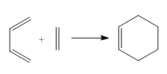
The reaction of cis butadiene and ethlyene was studied as a prototype cycloaddition reaction. The reaction obeys the Woodward Hoffmann Rule and is thermally allowed.
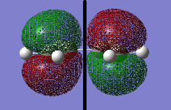
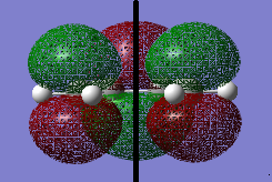
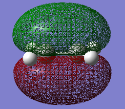
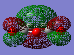
GaussView was used to build a cis butadiene and the molecule was optimized by Gaussian using AM 1 Semi-empirical and then B3LYP/6-31G* DFT method. The MOs of the molecule were visualized. The HOMO of cis butadiene is anti-symmetric (i.e. a) and the LUMO is symmetric (i.e. s) with respect to the plane (indicated by the black line in the middle).
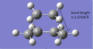
It was stated that the reaction has a envelop shape transition structure. A guess transition structure with a guess distance of 2.2 Å between bond break/form C-C atoms was drawn and optimized by the method 1 (TS Berny) in the Cope Rearrangement tutorial. The output structure was confirmed to be the transition state because (i) it had one and only one negative (imaginary) vibrational frequency and the animation showed the bond formation. (ii) the RMS Gradient Norm was nearly zero. The formation of the two new σ C-C bonds are synchronous. This was to compare with the lowest positive vibrational frequency in which the two bonds formed asynchronously.
The geometry of the transition structure was shown below. The bond length of the partly formed C-C σ bond was 2.27228 Å. From the literature, the typical sp3 and sp2 C-C bond length are 1.54 Å and 1.46 Å[3] and the van der Waal radius of the carbon atom is 1.70 Å[4]. The bond length of partly formed C-C was longer than sp3 and sp2 bond length and even the van der Waal radius of the carbon atom. It can be concluded that at this stage the two substrate were not forming bond and only having interactions weaker than van der Waal force.
ANIMATION ADDED
The MOs of the transition structure were visualised. Both of the HOMO and LUMO were symmetric with respected to the plane (black line).
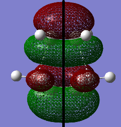
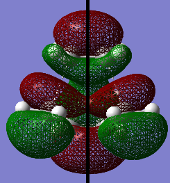
The HOMO at the transition structure was symmetric (i.e. s). It was formed by the HOMO of cis butadiene and the LUMO of ethylene because the two MOs were both symmetric, so they can interact strongly due to good orbital overlap. Also the energy difference between these two MOs was smaller than the energy between the LUMO of butadiene and HOMO of ethylene. The smaller energy gap between MOs also cause better orbital overlap. Therefore the reaction was allowed.
| cis butadiene | ethylene | |
|---|---|---|
| LUMO energy | -0.03012 | 0.01881 |
| HOMO energy | -0.22735 | -0.26664 |
Part 2. Cyclohexa-1,3-diene + maleic anhydride
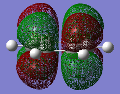
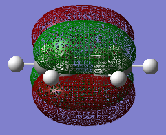
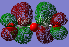
The two reactants was drawn and optimized using Semi-empirical AM 1 and then B3LYP/6-31G of Gaussian. The MOs were visualized. The LUMO of cyclohexa-1,3-diene was asymmetric and HOMO was symmetric with respect to the plane. The LOMO of maleic anhydride was asymmetric and HOMO was symmetric with respect to the plane. The optimized fragments were then copied and pasted into the same window and rearranged to two different structures to form the guessed endo and exo transition states. The dihedral angles of the planar fragments were adjusted to more like the transition structures. Then method 1 (TS=Berny) above was used to locate both of the transition structures, firstly AM1 then B3LYP/6-31G. The energies and geometries of the two transition structure were compared and studied.
ANIMATION ADDED ENDO
ANIMATION ADDED EXO
| B3LYP/6-31G* | electronic energy in a.u. | sum of electronic energy and zero-point energy in a.u. | sum of electronic energy and thermal energy in a.u. |
|---|---|---|---|
| cyclohexadiene | -233.24751 | -233.17583 | -233.17131 |
| maleic anhydride | -379.28483 | -379.22820 | -379.22337 |
| endo TS | -612.68340 | -612.50214 | -612.49179 |
| exo TS | -612.67931 | -612.49801 | -612.48766 |
| at 0 K | at 298.15 K | |
|---|---|---|
| ΔE of endo TS in kcal/mol | 61.6 | 60.9 |
| ΔE of exo TS in kcal/mol | 59.0 | 58.3 |
The energy of endo transition structure is lower than exo, therefore the activation energy of endo is lower than exo. The endo form would form more quickly than exo under kinetically controlled reaction condition. The energy difference between the two transition structures can be explained by their geometries and orbital interactions.
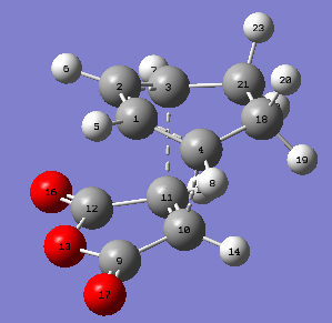
| carbon atoms | bond length in Å |
|---|---|
| C4-C10 | 2.26848 |
| C3-C11 | 2.26848 |
| C1-C4 | 1.39143 |
| C2-C3 | 1.39143 |
| C4-C18 | 1.51498 |
| C3-C21 | 1.51498 |
| C18-C21 | 1.55843 |
| C9-C10 | 1.47948 |
| C11-C12 | 1.47948 |
| C10-C11 | 1.39397 |
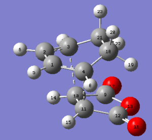
| carbons atoms | bond length in Å |
|---|---|
| C4-C11 | 2.29060 |
| C3-C10 | 2.29060 |
| C1-C4 | 1.39136 |
| C2-C3 | 1.39136 |
| C4-C18 | 1.51453 |
| C3-C21 | 1.51453 |
| C18-C21 | 1.55839 |
| C9-C10 | 1.47942 |
| C11-C12 | 1.47942 |
| C10-C11 | 1.39788 |
The C-C bond lengths within each fragment were similar for both cases. Yet the through space C-C bond lengths were more different. The exo form could be more strained because the partly formed C-C σ bond length for exo form was longer then endo. So the steric hinderance between the two fragments in exo form could be more significant. The C-C through space distance between the -(C=O)-O-(C=O)- fragment of the maleic anhydride and the C atoms of the 'opposite' -CH2-CH2- for the exo was 2.94575 Å, which was further apart than the corresponding distance for the endo form which was 2.89225 Å. However the endo form had a lower energy and was favored in kinetically controlled reaction. Therefore this led to the fact that there was secondary orbital overlap presents in the endo form that counteract and override the steric repulsion of the closer distance between -(C=O)-O-(C=O)- and the opposite -CH=CH-. This interaction does not exist in exo form. It can be explained by the HOMO of these two forms.
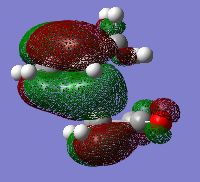
There were two kinds of interactions between the orbitals of the two fragments in the endo form, which were primary orbital interaction and the secondary orbital interaction. The primary orbital interaction was between the C-C bonds in the diene and the C-C bond in the dienophile. The secondary orbital interaction was between the C-C bonds in the diene and the C=O bonds in the dienophile. The HOMO diagram did not show the polarity on the C atom of the C=O bond but it should have overlap with the C=C orbital of the diene. This secondary orbital interaction lowered the energy of the endo transition structure. Since it did not exist in the exo form, the endo form had a lower energy and would form more quickly in the kinetically controlled reaction.

