Rep:Mod:wyc08mod3
Module 3: Transition States and Reactivity
Objectives
Transition structures on potential energy surfaces for the Cope rearrangement and Diels Alder cycloaddtion are characterised through a set of computational experiments. This involves numerically solving the Schrödinger equation using molecular orbital-based method, hence locating transition structures based on the local shape of a potential energy surface.
The Cope rearrangement
Cope rearrangement of 1,5-hexadiene is studied. Our objective here is to locate the low-energy minima and transition structures on the C6H10 potential energy surface and hence proposing a more preferred reaction mechanism.
The Cope rearrangement is a [3,3]-sigmatropic shift rearrangement involving a migration of a group from one point of attachment to another. Its mechanism has been subjected to controversy but its now widely accepted to occur in a concerted fashion. For 1,5-hexadiene,

Optimising the Reactants and Products at the HF/3-21G level
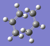
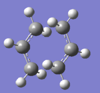
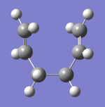
Two molecules of 1,5-hexadiene was created in Gaussview, one with an 'anti' linkage and one with the 'gauche' linkage. Both were then optimised at the HF/3-21G level (%mem = 250MB). Table 1 shows the jmol files of the two molecules together with their calculation summary. Symmetrisation gives the anti conformer a C2 symmetry and the gauche conformer a C1 symmetry. Comparing to conformers listed in Appendix 1 allows identification of the two structures.
|
| |||||||
| File Type | .chk | .chk | ||||||
| Calculation Type | FOPT | FOPT | ||||||
| Calculation Method | RHF | RHF | ||||||
| Basis Set | 3-21G | 3-21G | ||||||
| Final Energy / a.u. | -231.693 | -231.693 | ||||||
| RMS Gradient Norm / a.u. | 0.00000373 | 0.00000365 | ||||||
| Dipole Moment / Debye | 0.202 | 0.341 | ||||||
| Point Group | C2 | C1 | ||||||
| Log file | File:REACT ANTI OPTIMISATION(ANTI1).LOG | File:REACT GAUCHE OPTIMISATION(GAUCHE3).LOG | ||||||
| conformer identified from Appendix 1 | anti1 | gauche3 |
We expect any calculated energies would have been performed using the lowest energy conformer of the reactant as reference. In Table 2, more conformers were optimised and their energies were compared to those listed in Appendix 1.
|
|
|
| |||||||||||||
| File Type | .chk | .chk | .chk | .chk | ||||||||||||
| Calculation Type | FOPT | FOPT | FOPT | FOPT | ||||||||||||
| Calculation Method | RHF | RHF | RHF | RHF | ||||||||||||
| Basis Set | 3-21G | 3-21G | 3-21G | 3-21G | ||||||||||||
| Final Energy / a.u. | -231.68907065 | -231.69253530 | -231.68771616 | -231.69153035 | ||||||||||||
| RMS Gradient Norm / a.u. | 0.00000743 | 0.00000422 | 0.00000369 | 0.00000441 | ||||||||||||
| Dipole Moment / Debye | 0.0001 | 0.0002 | 0.4556 | 0.1281 | ||||||||||||
| Point Group | C2h | Ci | C2 | C2 | ||||||||||||
| Log file | File:REACT ANTI OPTIMISATION(ANTI3).LOG | File:REACT ANTI OPTIMISATION(ANTI2).LOG | File:REACT GAUCHE OPTIMISATION(GAUCHE1).LOG | File:REACT GAUCHE OPTIMISATION(GAUCHE4).LOG | ||||||||||||
| conformer identified from Appendix 1 | anti3 | anti2 | gauche1 | gauche4 |
In general, we would expect the gauche conformers to be of higher energies due to greater inherent steric hindrance. In the two conformers found above, they differ by a insignificant amount in energy. Looking at the energy values of the conformers in Appendix 1, it is found that the most stable 'gauche' conformer (gauche3) is indeed even more stable than the most stable 'anti' conformer (anti1). It can thus be inferred that steric repulsion is not the only dominating factor which determines the stability of conformers. To explain this unexpected energies, stereoelectronic factors could be considered. In gauche3, there is a favourable donation from the C=C π orbital into the C-H σ* orbital of the adjacent vinyl proton, and thus stabilising the conformer.
Optimising the Reactants and Products at the B3LYP/6-31G* level
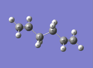
The Ci anti2 (identified in the previous section) was optimised this time, to the B3LYP/6-31G* level. Results obtained are compared to that obtained by optimising at the HF/3-21G level. Energy of Anti2 turned out to be of lower energy when computed at the B3LYP/6-31G*, for the point group symmetry remains unchanged. Geometry changes could be observed when looking at dihedral angles and bond lengths. Comparing to literature values
| HF/3-21G | B3LYP/6-31G* | Experimental[1] | |
| Energy /Hartree a.u. | -231.693 | -234.612 | |
| C12=C10 (C15=C1) bond length /Å | 1.316 | 1.334 | 1.340 ± 0.003 |
| C10-C7 bond length/Å | 1.509 | 1.504 | 1.508 ± 0.012 |
| C7-C4 bond length/Å | 1.553 | 1.548 | 1.538 ± 0.027 |
| C12-C10-C7 bond angle/° | 124.81 | 125.28 | 124.6 ± 1.0 |
| C12-C10-C7-C4 dihedral angle/° | -114.67 | -117.94 | |
| C10-C7-C4-C15 dihedral angle/° | 180.00 | 180.00 | |
| Symmetry | Ci | Ci |
It can be seen that the DFT/B3LYP (6-31G(d)) method ran a more accurate simulation and gave a better approximation of the geometry of the molecule, when compared to literature values. In terms of energy, the DFT/B3LYP (6-31G(d)) method results in a lower energy conformer, indicating a more accurate optimisation.
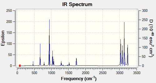
Frequency analysis was then carried out on the B3LYP/6-31G(d) optimised strucutre to confirm that optimisation has indeed run to completion: energy value obtained correspond to a minimum. Resultant vibrational frequencies are all real and positive. For a full .log output file:File:REAC ANTI OPTIMISATION (ANTI2DFT631G) FREQ.LOG.
|
| |||||||
| File Type | .chk | .chk | ||||||
| Calculation Type | FOPT | FOPT | ||||||
| Calculation Method | RHF | RB3LYP | ||||||
| Basis Set | 3-21G | 6-31G(d) | ||||||
| Final Energy / a.u. | -231.693 | -234.612 | ||||||
| RMS Gradient Norm / a.u. | 0.00000422 | 0.00003894 | ||||||
| Dipole Moment / Debye | 0.0002 | 0.0000 | ||||||
| Point Group | Ci | Ci |
Now, we are in a position to look at some thermodynamic information. Relevant data could be found in the Thermochemistry section in the frequency analysis output file. Under the vibrational temperatures a list of energies were printed (See Table 4). A similar calculation was also run for the same quantities at 0K using additional keywords 'Freq=ReadIsotopes'. Vibrational analysis at 0K fails at the 1st attempt. From the log. output file, it was realised that the Gaussian still reads temp at 298.15K even it was set to 0.0(K). Therefore, upon a 2nd attempt, temperature was set at 0.001 K and resulted in energy values listed in Table 4.
- The sum of electronic and zero-point energies refers to the potential energy at 0K including the zero-point vibrational energy (E = Eelec + ZPE)
- The sum of electronic and thermal energies refers to energy at 298.15K and 1atm of pressure including contributions from the translational, rotational, and vibrational energy modes at this temperature (E = E + Evib + Erot + Etrans)
- The sum of electronic and thermal enthalpies contains an additional correction for RT (H = E + RT); important when analysing dissociation reactions
- The sum of electronic and thermal free energies includes entropic contribution to the free energy (G = H - TS)
| 298.15 K/a.u. | 0 K/a.u. | |
| Sum of Electronic and Zero-point Energies | -234.469198 | -234.468761 |
| Sum of Electronic and Thermal Energies | -234.461850 | -234.468761 |
| Sum of Electronic and Thermal Enthalpies | -234.460906 | -234.468761 |
| Sum of Electronic and Thermal Free Energies | -234.500781 | -234.468761 |
Although the temperature set was not exactly at 0.0K but is small enough to draw some conclusion. It can be seen that as temperature decreases, the stability of the conformer increases (compare -234.612a.u. at 298.15K to -234.611a.u. at 0K). This is as expected since at higher temperatures, the molecule could access higher vibrational and rotational states. It is noteworthy to know that at 0 K, all energies are the same as there is essentially no thermal contributions; any energies will be comprised only of electronic and zero point energies.
Optimising the 'Chair' and 'Boat' Transition Structures
In this section, 'chair' and 'boat' transition structure optimisations were carried out. Optimisation techniques involved includes computing the force constants, using the redundant coordinator editor, as well as using QST2. Activation energies for the Cope rearrangement will also be calculated upon visualisation of reaction coordinate and running of the IRC (Intrinsic Reaction Coordinate).
Optimising an allyl fragment
There are two possible transition state structures in the Cope rearrangement of 1,5-hexadiene: a chair conformer which has a C2h symmetry and a boat conformer which has a C2v symmetry. Both 'chair' and 'boat' transition structures for the Cope rearrangement consist of two C3H5 allyl fragments.
Upon optimisation of the allyl fragment at an HF/3-21G level, we expect the resultant structure to resemble half of the actual transition structure. In a new window, two of the optimised fragment were then oriented so that they look roughly like the 'chair' transition state. Transition state optimisation was set up correspondingly. The important point here is that we have to create a transition state structure which has a geometry as similar as possible to the actual one. Otherwise, optimisation will be difficult since the negative direction of curvature could not be correctly located.
Optimising the 'Chair' Transition Structrue
Two different optimisation was carried out for the proposed 'chair' transition state. At a HF/3-21G level, the first optimisation is done via the Opt+Freq; Optimisation to TS(Berny) option. Force constants were chosen to be calculated once and additional keywords 'Opt=NoEigen' were added. The resultant structure has an imaginary frequency of 818cm-1.
The second optimisation was carried out using the frozen coordinate method. Here, we were to fix the bond forming/breaking distances to 2.2Å. This is done by freezing coordinate(s) of the terminal carbons of the allyl fragments under the 'Redundant Coord Editor' menu. Table 5 summarises the results obtained. The optimised structure obtained from indeed looks very similar to the one obtained by 'TS (Berny)' method, except that the bond forming/breaking distances are fixed. This optimised structure obtained from the 'freeze coordinate method' was then further optimised. This time, under the Redundant Coord Editor, the previously frozen bonds were selected and the 'Derivative' option was chosen correspondingly. After creating these new coordinates, a transition state optimisation was set up, with no force constant calculations ('Never' option chosen). Results obtained were shown in Table 6. This time, the terminal C-C bond lengths resemble those obtained from the TS (Berny) method. Also, both method gave imaginary frequency at -818cm-1. This imaginary frequency essentially shows the bond breaking/forming transition state of this electrocyclic rearrangement. In the light of mechanism of cope rearrangement, it can be inferred that the making and breaking of bonds in fact occur in a concerted manner, which is as suggested.
Optimising the 'Boat' Transition Structrue
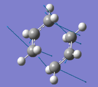
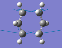
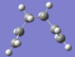
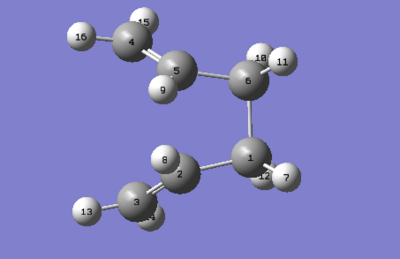
The 'boat' transition structure was optimised using the QST2 method, also at a HF/3-21G level. In this method, what we did was specifying the reactants and products so that subsequent calculation will interpolate between the two structures, hence suggesting the transition state between them. The important point here was to label correctly the reactant and product so that the product the product molecule would correspond to the numbering obtained if our reactant had rearranged. Figures below shows the numbering of the two molecules. After labelling, the first optimisation was run under Opt+Freq as the job type and TS (Berny) method is used. However, this optimisation failed. This is because Gaussian linearly interpolated between the two structures. It just simply tanslated the top allyl fragment.
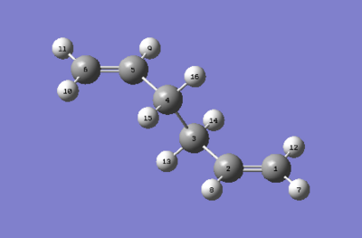
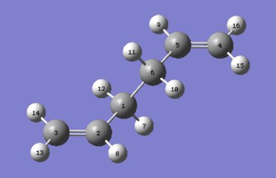
To improve, geometries of the reactant and the product were modified so they resemble more to the boat transition structure. The dihedral angle of the four central carbon (C2-C3-C4-C5 and C5-C6-C1-C2) atoms was set to 0o while the angle inside was reduced to 100o (C6-C5-C4 & C3-C2-C1). Adjustment were made to both the reactant and product. Using the modified structures, the QST2 calculation was set to run again. This time it converged to a boat transition structure. Results obtained also shows that there is one imaginary frequency at -840cm-1. Table 7 summarises results obtained.

| QST2 method at HF/3-21G level | |
| Optimised TS Structure | 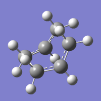 |
| Terminal C-C bond length/Å | 2.14 |
| Energy/a.u. | -231.603 |
| Imaginary Frequency/cm-1 | -840 |
| Animation File:CHAIR TS GUESS(B).LOG | 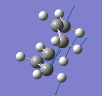 |
As mentioned, the imaginary frequency denotes a transition state. For the boat transitions structure, the imaginary frequency is more negative compared to that of the chair but still shows concerted bond breaking and making between terminal carbon atoms. The distance between terminal carbon atoms are longer compared to the chair TS, as reflected in their energy values (the chair transition structure is of slightly lower energy than the boat transition structure).
In general, we consider QST2 to be a more reliable method than TS Berny in the expense of time. In QST2, the structures of both the reactant and product are taken into consideration in calculations. In TS Berny calculations, there is no numbering of molecules and is more time efficient.
Intrinsic Reaction Coordinate Method
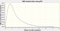
It is almost impossible to predict which product the chair or boat transition state will lead to. However, the Intrinsic Reaction Coordinate (IRC) method allows the problem to be solved. In Gaussian, the IRC method allows you to follow the minimum energy path from a transition structure down to its local minimum on a potential energy surface. Below illustrates this technique with the 'chair' transition structure as an example.
On Gaussian, IRC was selected under Job Type. The reaction coordinate was then set to compute in the forward direction due to the symmetrical properties of the molecule. The number of points along the IRC was set to 50 and force constant was set to once. The calculation in which the force constants were assumed constant and therefore only calculated once did not seem to have reached a minimum on the potential energy surface. It was decided that the best way was to recompute IRC with the force constants being computed at every step. Results obtained are shown in Table 8. The same could be done for the 'boat' transition structure.
Calculating the activation energies
Here, we are to calculate the activation energies for our reaction via both transition structures. To do this, we first re-optimised the chair and boat transition structures using the B3LYP/6-31G* level of theory and to carry out frequency calculations, starting from the HF/3-21G optimised structures. Results obtained are shown in Table 10.
| HF/3-21G | B3LYP/6-31G (d) | |||||
|---|---|---|---|---|---|---|
| Electronic Energy /a.u. | Sum of Electronic and Zero-point Energies (0 K) /a.u. | Sum of Electronic and Thermal Energies (298.15 K) /a.u. | Electronic Energy /a.u. | Sum of Electronic and Zero-point Energies (0 K) /a.u. | Sum of Electronic and Thermal Energies (298.15 K) /a.u. | |
| Chair TS | -231.619322 | -231.466700 | -231.461345 | -234.556982 | -234.414919 | -234.408989 |
| Boat TS | -231.602803 | -231.450929 | -231.445300 | -234.543093 | -234.401903 | -234.396009 |
| Reactant (Anti2) | -231.692535 | -231.539542 | -231.532571 | -234.611702 | -234.468774 | -234.461856 |
Activation energies could be calculated by subtracting the energy of the chair or boat transition structures from that of the Anti2 reactant. Calculated results are shown in Table 11, for 1 hartree = 627.509 kcal mol-1.
| HF/3-21G | B3LYP/6-31G* | Experimental Data | |||
|---|---|---|---|---|---|
| at 0K | at 298.15K | at 0K | at 298.15K | at 0K | |
| ΔE Chair | 45.71 | 44.69 | 33.79 | 33.17 | 33.5 +/- 0.05 |
| ΔE Boat | 55.61 | 54.76 | 41.96 | 41.32 | 44.7 +/- 2.0 |
The activation energies match well with literature values at 0K. The activation energy for chair TS is lower, suggesting a more favourable reaction pathway.
The Diels Alder Cycloaddition
Here, we will characterise transition structures of Diels Alder reactions using some of the methods described above, together with some inspection on shapes of some molecular orbitals. The Diels Alder reaction is a cycloaddition between a conjugated diene and a dienophile. Mechanistically speaking, it is often referred as a [4s+2s] cycloaddition. The π orbitals of the dienophile are used to form new σ bonds with the π orbitals of the diene. The reaction could occur in a concerted fashion or not depends on the number of π electrons involved. In terms of molecular orbitals, we describe the reaction as interactions of HOMOs and LUMOs.
Plotting the HOMO(S) and LUMO(s) of cis butadiene and Ethylene
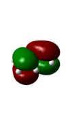
To start with, cis butadiene and ethylyene were built in Gaussian, followed by optimisation using the AM1 semi-empirical molecular orbital method. The HOMO and LUMO were plotted accordingly and results are shown in Table 12.
As mentioned, visualisation of molecular orbitals together with their relative energies help to determine whether a reaction between molecules will be possible. From Table 12, it can be seen that the HOMO of the cis butadiene and LUMO of the ethylene are both antisymmetric whereas the LUMO of butadiene and HOMO of ethylene are both symmetric. We would thus expect interaction to occur between the HOMO of butadiene and LUMO of ethylene, for interactions usually take place between specific sets of orbitals to maintain the orbital symmetry.
Computation of the ethylene + cis butadiene transition structure
The transition structure of the Diels Alder cycloaddition is obtained via optimisation to a TS(Berny) to a Semi-emipirical/AM1 level of theory. Results obtained are shown below in Table 13. A typical sp3 C-C bond length is about 1.544Å, while a sp2 bond length is 1.338Å [2]. The van de Waals radius of carbon is 1.70Å [3]. From the transition structure obtained above, the C-C bond length is 2.12Å, which is longer than a typical sp3 C-C bond length, yet shorter than two times the van der Waals radius of carbon. his intermediate C-C indicates that a C-C bond is in the process of forming. On the other hand, a shorter C=C double bonds suggest that they are breaking to facilitate bond formation (See Table 14).
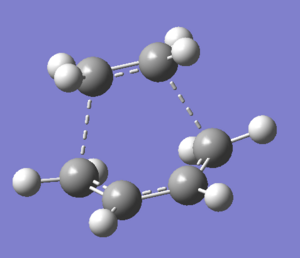
| TS(Berny) | |
|---|---|
| Energy / Hartree | 0.11163 |
| Bond forming length / Å | 2.1195 |
| Bond forming length / Å | 2.1191 |
| Imaginary frequency / cm-1 | -957 |
| Structure | 
|
| Bond length / Å or bond angles / ° |
TS(Berny) |
|---|---|
| C7 - C10 | 1.38 |
| C10 - C12 | 1.40 |
| C12 - C14 | 1.38 |
| C14 - C1 (Bond forming) | 2.12 |
| C1 - C4 (Ethene bond) | 1.38 |
| C4 - C7 (Bond forming) | 2.12 |
| C4-C7-C10 angle | 99.3 |
| C12-C14-C1 angle | 99.3 |
| C14-C1-C4 angle | 109.9 |
Molecular Orbitals Analysis of TS
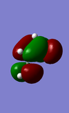
The HOMO and LUMO of the transition structure are plotted as below in Table 15. They help to determine to which MO interaction is occurring between the ethylene and butadiene.
| HOMO | LUMO | |
|---|---|---|
| Molecular Orbital | 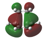 |
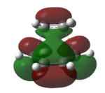
|
| Energy / Hartree | -0.32393 | 0.02315 |
| Symmetry (wrt plane) |
Antisymmetric | Symmetric |
From Table 15, it can be seen that the HOMO is antisymmetric with respect to the plane diving the C-C bond in butadiene, as in that of the C=C double bond in ethylene. The LUMO, on the other hand is symmetric with respect to plane. The HOMO results from interaction between antisymmetric HOMO of butadiene and antisymmetric LUMO of ethene. This pi and pi* interaction corresponds well to the Diels Alder reaction, involving 6 pi electrons.
Vibrations of Transition State Structure
Certainly, we could carry out a frequency analysis to confirm the presence of a transition state. An imaginary vibration is found at -957cm-1, which corresponds to a bond formation vibration. The synchronous nature of the vibration shows that the reaction occurs in a concerted fashion. This again matches well with what is expected in a Diels Alder cycloaddition.
To study the regioselectivity of the Diels Alder Reaction: reaction of cyclohexa-1,3-diene and maleic anhydride
Cyclohexa-1,3-diene undergoes a facile reaction with maleic anhydride to give primarily the endo product. Under a kinetic control, we expect the exo transition state to be of higher in energy. To investigate this, both the endo and exo transition structures are located and optimised. This time, the QST2 method is used instead of optimising it to a TS(Berny).
As usual, the reactants were first optimised prior to locating a transition structure, Table 16 below shows the HOMO and LUMO of maleicanhydride and cyclohexa-1,3-diene, together with their corresponding energies.
| Structure | HOMO | LUMO | Energy / a.u. | ||||
| maleicanhydride |
|
 |
 |
HOMO:-0.44185; LUMO:-0.05949 | |||
| Cyclohex-1,3-diene |
|
 |
 |
HOMO:-0.32073 LUMO:0.01692 |
Similar to the above reaction between cis butadiene and ethylene, we expect there is a HOMO-LUMO interaction between reactants in the formation of a transition structure. Also, the symmetry of the orbitals must be maintained and only orbitals of the same symmetry could interact. Here, the pair of interacting orbitals would be LUMO of cyclohexadiene and HOMO of maleic anhydride, vice versa.
Optimisation of the endo- and exo- Transition States
This time, the transition structures are located via the QST2 method, optimising to the Semi-empirical/AM1 level of theory. As described in the 'Optimising the boat and chair transition structure' section, it involved creating the reactants and the product in a 'MolGroup' in Gaussview. Atoms also have to be numbered accordingly. Table 17 shows the Exo and Endo TS obtained:
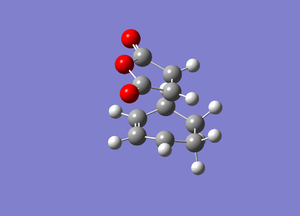
| Exo TS AM1 |
Endo TS AM1 | |||||||
| transition state |
|
| ||||||
| Energy / Hartree a.u. | -0.050503 | -0.051594 | ||||||
| Sum of electronic and thermal energies / Hartree |
0.14479 | 0.14359 | ||||||
| Imaginary Frequency / cm-1 | -811 | -805 | ||||||
| LOG output files | File:EXO TS OPT.LOG | File:ENDO TS OPT.LOG |
The endo- TS is of lower energy compared to that of exo- TS. This result is consistent with our suggestion: in this kinetically control, irreversible reaction, the primary product is formed from a lower TS, which is found to be the endo-TS. Hence the endo- product is formed as the major product. The Exo- TS is indeed more strained and is experiencing a greater steric hindrance (see geomety analysis below).
Molecular Orbitals of the endo- and exo- Transition States
Again, we will be looking at the HOMO and LUMOs of the transition structures in order to yield information regarding interacting pairs of orbitals. Table 18 shows the HOMO and LUMOs plotted in Gaussian. It can be seen that both the HOMO and LUMO of the endo and exo transition state are antisymmetric. It can be identified that the reaction involves interction between the HOMO of cyclohexa-1,3-diene and the LUMO of maleicanhydride.
| Endo TS | Exo TS | ||
|---|---|---|---|
| HOMO (-0.34506 a.u.) | LUMO (-0.03569 a.u.) | HOMO (-0.34276 a.u.) | LUMO (-0.04044 a.u.) |
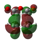
|
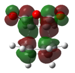
|
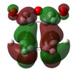
|
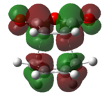
|
| Anti-symmetric | Anti-symmetric | Anti-symmetric | Anti-symmetric |
We might also want to look at some geometrical information here. We looked at the bond forming/breaking distances in the reaction between butadiene and ethylene to confirm our structure found is a transition state structure. A similar analysis could be done for the exo- and endo- transition structures. Table 19 summarises the results obtained.
The C-C bond forming/breaking distance is 1.39Å, which is consistent with the concerted formation of bonds. In the exo TS, the distance between C=O group and opposite CH2CH2 group is 2.95Å while the corresponding distance for the endo TS is 2.89Å. It can be inferred that the endo isomer experience greater steric repulsion, which perhaps explains the energy difference.
| Parameter | Endo / Angstroms | Exo / Angstroms |
|---|---|---|
| Length of new/forming C-C sigma bonds | 2.16 | 2.17 |
| Distance between C=O group and opposite CH2CH2 group | 2.89 | 2.95 |
| Distance between the anhydride C=C and the diene C=C | 2.71 | 2.64 |
| Distance between the two C=O groups | 2.28 | 2.28 |
Secondary Orbital Interactions
We might also want to consider secondary orbital interactions here. In the endo transition state, we see that the distance between C=O group and opposite CH2CH2 group is much shorter relative to that in the exo transition state. This indeed could be accounted to the presence of secondary orbital interactions occurring between the πC-C orbital of cyclo-1,3-hexadiene and π*C=O orbital of maleic anhydride, hence stabilising the transition structure. Such an interaction, however, does not occur in the endo state.
References
- ↑ G. Schultz, I. Hargitta, J. Mol. Struc., 1995, 346, 63-69. DOI:10.1016/0022-2860(94)09007-C
- ↑ M. J. S. Dewar and H. N. Schmeising, Tetrahedron, 1960, 11, DOI:10.1016/0040-4020(60)89012-6
- ↑ A. Bondi, J. Phys. Chem., 1964, 68, 441. DOI:10.1021/j100785a001


