Rep:Mod:mw1409module3
The Cope Rearrangement Tutorial
The Cope Rearrangement of 1,5-hexadiene is a classic [3,3]-sigmatropic shift rearrangement which is generally accepted to pass through a cyclic chair or boat transition state and occur in a concerted fashion. In this tutorial Gaussian will be used to calculate activation energies and enthalpies.
Optimising the reactants and products
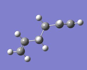
In Gaussview, a molecule of 1,5-hexadiene was drawn with the four central C atoms having an antiperiplanar relationship and the structure was cleaned.
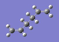
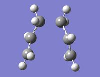
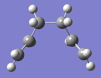
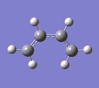
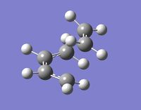
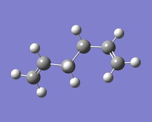
The structure drawn was then optimised at the HF/3-21G level of theory and 250MB of memory specified. The calculation output can be found here: (DOI:10042/to-10123 ) The energy of the optimised molecule (see left) was -231.69260a.u. but no point group was reported in the file summary section. The structure also had a dipole moment of 0.2021Debye, and was not symmetrical. The symmetrize function was used and the molecule was identified to have a point group of C2.
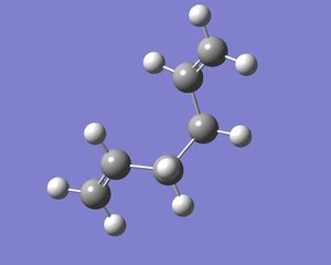
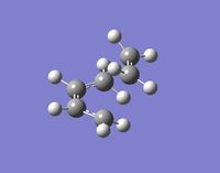
Again in Gaussview, a molecule of 1,5-hexadiene was drawn, this time with a gauche relationship in the central four C atoms. Since in the gauche relationship, the two bulky C=C groups are brought closer together, it would be expected that the gauche conformer would be higher in energy than the anti structure. This structure was also cleaned and optimised at the HF/3-21G level (DOI:10042/to-10124 ). The energy of the optimised molecule was -231.69153a.u. which is as expected, slightly higher than that for the anti conformer. The dipole moment was 0.1281Debye and was not symmetrical. The symmetrize function was used and the point group determined to also be C2.

Based on the results above, the lowest energy conformation is expected to be a conformer with some for of anti relationship for the central four C atoms. The initial starting point is with the anti conformer above which has the two C=C groups pointing in the same direction, looking at the image above, they are both pointing down into the screen. Therefore if one group was rotated so that it pointed out, the separation between the two groups may be larger on optimisation and the energy of the conformer may be lower.
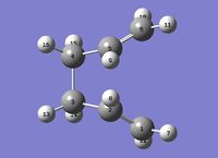
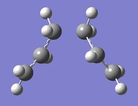
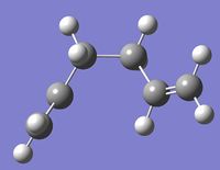
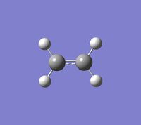
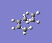
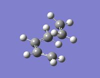
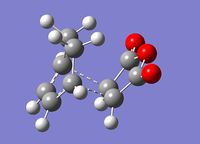
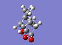
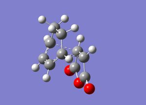
This approach was attempted and the anti2 conformer (left) was obtained (DOI:10042/to-10120 ). This was optimised using the same method and basis set as the previous optimisations. The energy obtained was -231.69254a.u. which is slightly higher than that for anti1, however, the dipole moment of this conformer was 0Debye and the point group after symmetrizing was Ci.
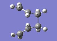
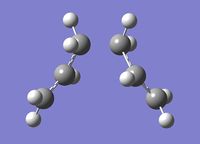
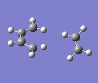
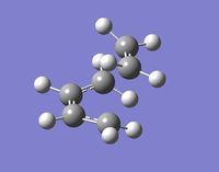
Another anti conformer was tried for comparison, this was anti3 (right). The energy obtained after optimisation (DOI:10042/to-10122 ) was -231.69097a.u. which was much higher than the other conformers so far tried. This is because the two C=C groups are brought quite close together and there is therefore likely to be some steric strain. This conformer was completely unsymmetrical with a point group of C1
In Appendix 1 of the Module 3 instructions wiki, the low energy conformers were tabulated. Comparing with my conformations optimised, I was able to confirm energies ad point groups. My anti1 conformer was found to be identical to the anti1 conformer in the table with identical energy and point group. My gauche1 conformer was the same as the gauche4 conformer in the table with the same energy and point group. My anti2 conformer was identical to the anti2 conformer in the table with the same energy and point group. My anti3 isomer had the same structure as the anti4 isomer in the table and the energies and point groups were also the same.

| Opt 1 | Opt 2 | |
| C=C-C | 124.8o | 125.3o |
| C-C-C | 11.3o | 112.7o |
| Dihedral | 114.7o | 118.5o |
The anti2 structure was re-optimised at the B3LYP/6-31G(d) level. This is a higher level of theory than the HF/3-21G level. The files can be found here: DOI:10042/to-10121 The re-optimised structure (left) had an energy of -234.61170a.u. although this cannot be compared with the other energies as a different method and basis set has been used. The point group has remained as Ci.
The structure of the anti2 conformer after the second optimisation is clearly different to that after the first optimisation. The apparent difference is that there has been rotation of the C=C groups around the single bonds 2 and 4. In general the bond angles in the twice optimised structure are larger than those in the structure after the low level optimisation (see table , right)
The energy values obtained from the optimisation represent the energies of molecules on a bare potential surface. to be comparable to real energies, the molecule must undergo frequency analysis which allows additional terms to be included. The B3LYP/6-31G optimised structure was submitted to a frequency calculation at the same level of theory. The resulting vibrations were checked to ensure that there were no negative values(DOI:10042/to-10013 ). This confirmed that the molecule was at a minimum energy conformation.
Looking at the Gaussian output file, in a section headed
 -------------------
 - Thermochemistry -
 -------------------
were a list of energies:
Sum of electronic and zero-point Energies=           -234.469204
Sum of electronic and thermal Energies=              -234.461857
Sum of electronic and thermal Enthalpies=            -234.460913
Sum of electronic and thermal Free Energies=         -234.500778
The sum of electronic and zero-point energies is the potential energy at 0K including the zero-point vibrational energy (E=Eelec + ZPE). The sum of electronic and thermal energies is the energy at 298.15K and 1atm of pressure, including contributions from translational, rotational and vibrational modes at this temperature (E = E + Evib + Erot + Etrans). The sum of electronic and thermal enthalpies has the additional correction for RT (H = E + RT). The sum of electronic and thermal free energies includes the entropic contribution to the free energy (G = H - TS). All these energies are given in units of Hartrees so in terms of kJmol-1 they are:
Sum of electronic and zero-point Energies=           -615.482kJmol-1
Sum of electronic and thermal Energies=              -615.462kJmol-1
Sum of electronic and thermal Enthalpies=            -615.460kJmol-1
Sum of electronic and thermal Free Energies=         -615.565kJmol-1
Optimising the "Chair" and "Boat" Transition Structures
The transition structures for the Cope rearrangement consist of two C3H5 allyl fragments positioned 2.2Å apart. The chair conformation transition structure has a point group of C2h and the boat conformation transition structure has point group C2v.
The transition structures were optimised using three different methods:
- By computing the force constant matrix in the first step of the optimisation which is updated as the optimisation proceeds.
- By using the redundant coordinate editor to freeze the reaction coordinate and minimising the rest of the molecule, before unfreezing the reaction coordinate again and optimising the whole transition state.
- By using QST2
The chair transition state was approximated by positioning two allyl fragments together in a chair like structure. The terminal ends of the fragments were placed approximately 2.2Å apart.
This transition state was optimised first using method 1 above. The method and basis set used was HF/3-21G. Under the calculation menu, the job type Opt+Freq was selected and the option for optimising to a transition state chosen. The force constants were calculated once and the additional keywords "opt=noeigen" were added to prevent the calculation crashing if more than one imaginary frequency was detected. The optimised file can be found here: DOI:10042/to-10039 The frequency analysis yielded one imaginary frequency of -817.93cm-1 so confirmed that this had been successfully minimised. This vibration corresponds to the Cope rearrangement as it is the stretch between the terminal allyl C atoms where the bonds are broken/formed. The bond forming/breaking bond lengths were found to be 2.02041Å in the optimised structure with the
The initial approximate structure was also optimised using method 2 above. The redundant coordinate editor was used to select the terminal allyl carbons that form/break a bond in the reaction and the coordinates were frozen. The distance between the two atoms was also set to 2.2Å. This was then optimised using the HF/3-21G method and basis set. When the optimisation was complete (DOI:10042/to-10116 ), the redundant coordinate editor was used to select the bonds that were frozen and set the optimisation to differentiate along those coordinates. The optimisation to a transition state was again run and the optimised geometry (DOI:10042/to-10117 ) compared with the optimised structure using method 1. In this case the imaginary frequency resulting was -818.03cm-1 and the bond breaking/forming bond length for this optimisation method was 2.01990Å. This is a slightly shorter bond distance than results from the optimised structure from method 1.
The QST2 method was used to optimise the boat transition structure. The reactant and product for the reaction were specified and the calculation tries to find the transition state between them.

As can be seen in the diagram on the left, the only difference between the reactant and product molecules is the numbering of the atoms so to specify the reactant, the optimised anti2 molecule was copied into a new molecule group and then another added to the same molecule group in Gaussview. The atoms of the second copy was renumbered to represent the product molecule. It was found that great care had to be taken in renaming the H atoms too in order that Gaussian could interpret the reaction correctly. The renumbered reactant and product molecules are shown below:
| Reactant | Product |
An Opt+Freq calculation was set up and optimisation was selected to a transition state, using the TS(QST2) option. (DOI:10042/to-10118 ) This initial calculation failed, on opening the resulting checkpoint file, it could be seen that the result looked a little like a dissociated form of the chair transition structure. This shows that the interpolation between the reactant and product resulted in a translation of the allyl fragment containing the first 3 C atoms but no rotation around the central C-C bond:
| |||
| Transition State |
To obtain an optimised boat transition structure, the original reactant and product geometries were modified to more closely resemble the transition state. The central C-C-C-C dihedral angle was set at 0o and the two C-C-C single bond angles were set to 100o on both the reactant molecule and the product molecule as shown below:
| Reactant | Product |
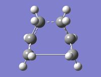
The QST2 calculation was repeated and this time, was successful (DOI:10042/to-10119 ), producing the boat transition structure below:
| |||
| Transition State |
This molecule showed only one imaginary vibration at -840cm-1 which corresponds with the C-C stretch of the two breaking/forming bonds.
This showed the limitation of the QST2 method as it can only optimise a transition state successfully if the reactant and product geometries are close to that of the transition state. However, it does require fewer input details than the previous two methods and is fully automated.
Looking at the optimised chair and boat transition states, it is very difficult to tell which low energy conformers looked at in the first section might correspond to reactants and products. To find these, the intrinsic reaction coordinate (IRC) method can be used in Gaussian to follow the minimum energy path from the transition state to its local minimum.
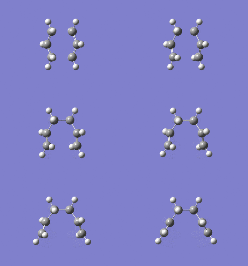
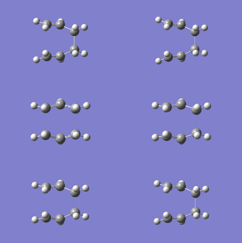
The optimised chair transition structure using the redundant coordinate editor method above, was submitted for an IRC job. As the reaction coordinate in this case is symmetrical, it was chosen to only compute it in the forward direction. The force constants were set to be calculated once at the beginning of the job. The number of additional points along the IRC were set to 50. The output from this calculation can be found here:IRC 1 - DOI:10042/to-10114 On viewing all the intermediate geometries resulting in the formatted checkpoint file, it is clear that a minimum geometry has not yet been reached. There were 21 intermediate geometries generated in this calculation but as can be seen below, none resemble the minimum energy structures determined previously:
| Intermediate geometries calculated |
There are three methods for finding the actual minimum.
- Taking the last structure on the IRC and then minimising normally.
Structure 21 was copied into another molecule group and minimised using a HF/3-21G method and basis set (DOI:10042/to-10129 ). This resulted in a structure as shown below which had an energy of -231.69166702a.u.
| Structure 21 | After optimisation |
- Running the IRC calculation again using a larger number of points until it reaches a minimum.
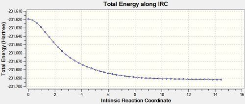
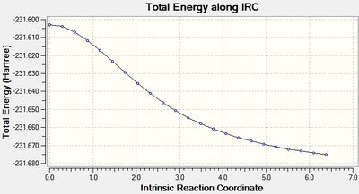
The IRC job for the chair transition state was set up as before but with the number of points set to 100 (IRC 2 - DOI:10042/to-10131 ). This time, there were also 21 intermediate geometries obtained, and they had the same structure as those in the previous step. Repeated once more with the number of points set to 1000 had the same result (IRC 3 - DOI:10042/to-10137 ). Both the final structures from these calculations were optimised and were shown to be identical to that obtained in the previous step. This is because, as the IRC plot below shows, when the force constants are calculated only once, only 21 steps takes the structure to a minimum, hence adding more point in this case makes no difference.
| Plot of IRC when force constants calculated only once |
- Redoing the IRC specifying that force constants should be calculated at every step.
Again, the IRC job was set up for the optimised chair transition structure and the reaction coordinate selected to be computed in the forward direction only. This time the option to always calculate the force constant was selected and the number of points set at 50 (IRC 4 - DOI:10042/to-10154 ). This time, there were 47 intermediate structures produced and the final structure looked very similar to that produced from the optimisation of the structures in the previous sections. The energy of this structure was -231.69166427a.u. which is slightly higher than that for the previously optimised structures. This structure was also optimised and resulted in an optimised structure with a very slightly higher energy of -231.69166699a.u. than the previously optimised structures and also slightly different geometry.
| Structure 47 | After optimisation |
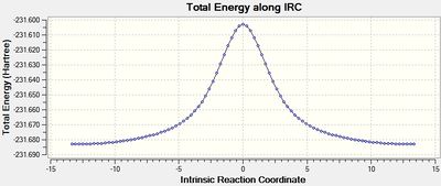
The IRC plot for this calculation, clearly shows that a much more certain minimum has been reached as the gradient is now very close to 0.
| Plot of IRC when force constants were calculated at every step |
The geometries and energies of all the structures are detailed in the tables below:
|
|
All the structures obtained are similar to the gauche2 structure in Appendix 1 and have the same energy to the level of accuracy shown.
The optimised boat transition structure was submitted for an IRC job, as above it was also computed only in the forward direction and with 50 points. This time, it took 23 points before the structure minimised (IRC 1 - DOI:10042/to-10161 ).
| Intermediate geometries calculated |
The IRC pathway can be seen on the plot below:
| Plot of IRC when force constants calculated only once |
The final structure was again optimised as above at the HF/3-21G level(DOI:10042/to-10162 ):
| Structure 23 | After optimisation |
The boat conformation was also subjected to an IRC calculation with all the force constants calculated. This time, the IRC was calculated in both directions. In this case there were 93 intermediate geometries and the final geometry looked very similar to the optimised reactant molecule. This structure was also optimised.
| Intermediate geometries calculated |
The IRC plot for this calculation is also shown below:
| Plot of IRC when force constants calculated only once |
| Structure 23 | After optimisation |
The optimised structure obtained is similar to the gauche3 structure in Appendix 1 which is the lowest energy isomer and has the same energy as the reactant here to the level of accuracy shown.
The geometries and energies of the reactant obtained from the different methods are shown in the table below:
|
|
There is clearly a much greater difference between the structures obtained from only computing the force constants once and computing them at every step compared with for the chair transition state. The energy of the structure obtained from the latter method is significantly lower and shows the advantages of that method.
Calculating the activation energies for the reactions
The chair transition state was reoptimised using the B3LYP/6-31G* method and basis set and the energy of the structure recorded. The boat transition state was also reoptimised at the same higher level. The chair and boat reactants were also reoptimised at this level and the energies of these are shown below:
| Chair TS | Chair reactant | Boat TS | Boat Reactant | |
| HF/3-21G | -231.61932198 | -231.69166702 | -231.60280247 | -231.69266108 |
| B3LYP/6-31G* | -234.55698284 | -234.61068812 | -234.54309298 | -234.61132934 |
As can be seen, the difference in energy between the chair transition structure and the corresponding reactant is 0.07234504a.u. at the HF/3-21G level while the difference for the boat structure at the same level is 0.08985861a.u. At the higher level of theory however, the energy difference for the chair transition state and reactant was 0.05370528a.u. and for the boat transition state and reactant was 0.06823636a.u. These energy differences are approximately 0.02a.u. smaller at the higher level of theory. Looking at the structures for the reoptimised chair and boat transition states, they look very similar to the structures obtained at the lower level of theory and the same is true of the reactant molecules.
| HF/3-21G | B3LYP/6-31G* | |||||
|---|---|---|---|---|---|---|
| Electronic energy | Sum of electronic and zero-point energies | Sum of electronic and thermal energies | Electronic energy | Sum of electronic and zero-point energies | Sum of electronic and thermal energies | |
| at 0 K | at 298.15 K | at 0 K | at 298.15 K | |||
| Chair TS | -231.619322 | -231.466696 | -231.461337 | -234.556983 | -234.414931 | -234.409010 |
| Chair reactant | -231.691667 | -231.538704 | -231.531794 | -234.610688 | -234.468263 | -234.460957 |
| Boat TS | -231.602802 | -231.450927 | -231.445298 | -234.543093 | -234.402341 | -234.396006 |
| Boat reactant | -231.692661 | -231.539486 | -231.532646 | -234.611329 | -234.468693 | -234.461464 |
At 0K the energy difference (activation energy) between the reactant and the chair transition state at the higher B3LYP/6-31G* level is 0.053332 Hartrees which is equal to 33.5 kcal/mol. This the same as the experimental value of 33.5 ± 0.5 kcal/mol and therefore lies well within the margin of experimental error. For the boat transition state the activation energy is 0.066352 Hartrees which equates to 41.6 kcal/mol. The experimental value was found to be 44.7 ± 2.0 kcal/mol so the calculated value obtained here falls outside the experimental error margins being 1.1 kcal/mol lower than the lower bound for the experimental measurement.
The Diels Alder Cycloaddition
As with the sigmatropic rearrangement above, the diels-alder reaction is also a pericyclic reaction.
Optimising cis-butadiene and visualising MOs
Gaussview was used to create a molecule of cis-butadiene which was then optimised using the AM1 semi-empirical method (DOI:10042/to-10210 ).
| Optimised cis-butadiene |
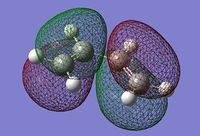
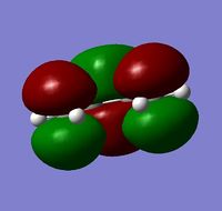
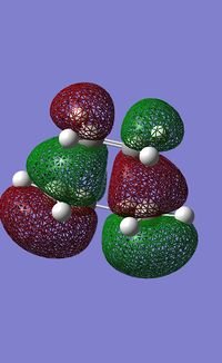
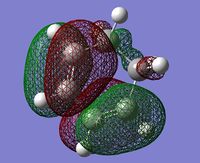
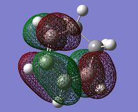
The HOMO and LUMO for the molecule were then plotted and are shown below:
| HOMO | LUMO |
The HOMO is antisymmetric while the LUMO is symmetrical in a plane perpendicular to the plane of the butadiene molecule.
Optimising the Diels Alder transition state
First the transition state butadiene and ethene fragments were created and optimised. The opt+freq calculations were run using the semi-empirical AM1 method producing the optimised fragments shown below (DOI:10042/to-10211 ,DOI:10042/to-10212 ).
| Optimised butadiene fragment | Optimised ethene fragment |
These fragments were arranged in a 'guess' transition structure and submitted for an optimisation calculation by computing the force constants once at the beginning of the calculation. The AM1 method was used again and the job type set as opt+freq. The calculation was selected to be an optimisation to a transition state (Berny) and the force constants set to be calculated once. The additional keywords opt=noeigen were also included to stop the calculation from crashing if more than one imaginary frequency was detected. This calculation failed after some time running and when the checkpoint file was opened, it was clear that the guess structure must have been too far from the exact structure as the ethene fragment had moved away from the butadiene fragment (DOI:10042/to-10217 ).
| Guess transition state structure | Failed optimisation of transition state |
The redundant coordinate editor method was therefore attempted. The editor was used to fix the coordinates of the pairs of C atoms involved in the formation of the new C-C bonds in the product and the structure optimised to a minimum using the AM1 semi-empirical method (DOI:10042/to-10213 ). The structure produced was then reoptimised, this time to a transition state with the bond breaking/forming coordinates unfrozen. The force constants were set to be calculated 'never'. This calculation failed very quickly (DOI:10042/to-10214) ) so instead it was run using the HF/3-21G method which was successful and then the final structure submitted again for a AM1 optimisation (DOI:10042/to-10216 ). The structures produced are shown below:
| After first ts optimisation - coordinates fixed | Attempted second optimisation of unfrozen coordinates, AM1 method | Second optimisation, HF/3-21G method | Final optimisation, AM1 method |
From looking at the structures they appear very similar
The final optimised transition structure had an energy of 0.11165465a.u. and one imaginary frequency at -956.28cm-1 which shows that it is at a transition state. The vibration corresponded with the stretching of the forming C-C bonds. The geometry of the transition structure is tabulated below along with the geometries of the butadiene and ethylene fragments:
| Ethylene Fragment | Butadiene Fragment | Transition state | |
| Ethylene C-C | 1.32594Å | - | 1.38292Å |
| Central butadiene C-C | - | 1.44952Å | 1.39748Å |
| Terminal butadiene C-C | - | 1.33498Å | 1.38186Å |
| Forming/Breaking C-C | - | - | 2.11923Å |
| Butadiene C-C-C | - | 125.67286o | 121.18413o |
| Forming/Breaking C-C-C (but) | - | - | 99.33819o |
| Forming/Breaking C-C-C (eth) | - | - | 109.94201o |
| Energy | 0.02619024 | 0.04879725 | 0.11165465 |
The bond forming/breaking C-C length is much longer than any other bond length, this is as expected as it is in transition between a bond and no bond. The C-C bond in the ethylene fragment is significantly longer in the transition state structure as are the terminal butadiene C-C bonds. The central butadiene C-C bond is shorter in the transition state structure and is closer in length to the other bonds. The butadiene molecule optimised above shows typical sp3 and sp2 C-C bond lengths. The C=C bond length there is 1.33506Å while the C-C bond length is 1.44948Å. The Van Der Waals radius of carbon atoms is 1.70Å in simple hydrocarbons[1] which means that in a normal C-C bond, the bond length is much shorter than the Van Der Waals radii of the two atoms. The C-C bond forming/breaking is 2.12Å so the Van Der Waal radii of the two atoms involved are overlapping and there is an attractive interaction. The butadiene fragment C-C-C angle is smaller in the transition structure and closer to the ideal sp2 angle of 120o. The energy of the transition structure is significantly higher than that of the reactants.
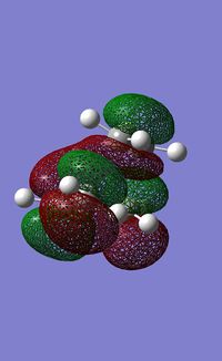
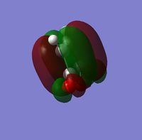
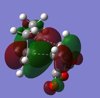
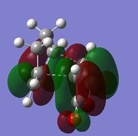
The HOMO and LUMO of the transition structure are shown below. The HOMO is antisymmetric whereas the LUMO is symmetrical in a plane through the centre of the molecule perpendicular to the plane of the butadiene fragment.
| HOMO | LUMO |
The HOMO of the transition state structure is formed of the HOMO of the butadiene fragment interacting with the LUMO of the ethylene fragment. The reaction is allowed as the two orbitals have the same symmetry and hence have a significant overlap density meaning that the orbitals can interact.
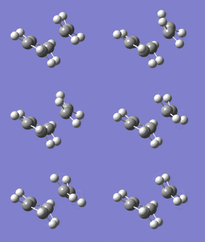
The imaginary stretch of the forming C-C bonds is illustrated below along with the lowest positive frequency:
| Imaginary frequency | Lowest positive frequency |
The formation of the two bonds is synchronous in a Diels Alder reaction. The lowest positive frequency vibration is of much lower intensity than the imaginary vibration and corresponds with a rocking motion in the ethylene fragment and the butadiene fragment.
Regioselectivity of the Diels Alder Reaction
When the diene and dienophile are substituted, the issue of regioselectivity becomes important as the reactants can approach each other in two distinct orientations. This effect can be seen in the reaction between cyclohexadiene and maleic anhydride. The major product is the endo product 3. Since the reaction is kinetically controlled it is therefore expected that the exo transition state is higher in energy.
| Regioselective reaction |
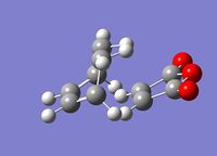
To optimise the transition states, first the reactant fragments were constructed and optimised using the semi-empirical AM1 method (DOI:10042/to-10205 , DOI:10042/to-10206 ). The expected exo product molecule was also constructed and optimised using the same level of theory (DOI:10042/to-10209 ). The transition structure was determined using the QST2 method. The two reactant molecules were arranged in an approximate transition state geometry and the atoms renumbered to correspond with those on the product molecule. The QST2 calculation was set up by selecting an opt+freq job to optimise to a transition state(QST2). The semi-empirical AM1 method was used. The calculation was successful (DOI:10042/to-10207 )and the optimised transition state is shown below:
| Exo transition State guess structure | Optimised exo product molecule structure | Optimised exo transition state structure | Imaginary vibration |
The vibrational spectrum for the transition state showed one imaginary frequency at -812.33cm-1. This confirms that the structure is a transition state and the vibration corresponds with the two forming C-C bonds.
The optimisation of the endo transition state was accomplished in the same way. The reactants were aligned in a geometry that approximates the transition state and the product structure was also optimised using the AM1 semi-empirical method (DOI:10042/to-10204 ). The QST2 optimisation to a transition state was used to interpolate between the two and the transition state successfully optimised (DOI:10042/to-10208 ).
| Endo transition State guess structure | Optimised endo product molecule structure | Optimised endo transition state structure | Imaginary vibration |
The vibrational spectrum showed one imaginary frequency at -806.37cm-1 which confirms that a transition state has been reached and corresponds with the forming C-C bonds of the product.
The Geometries of the two transition structures are compared below:
The two transition structures are compared in the table above. Where distances are labeled (1) or (2), (1) means that it is the bond pictured closest in the image while (2) is the corresponding bond that is further away in the images above. As expected, the exo transition state is higher in energy than the endo transition state, therefore confirming that the reaction is kinetically controlled. The difference in energy is 0.00108501 Hartrees at this level of calculation (semi-empirical AM1 method). In both the transition structures, the forming C-C bond lengths are slightly different showing that the formation of the bonds is in a concerted asynchronous mechanism and one bond is formed more properly than the other in the transition state and hence is shorter. This is in contrast to the bond formation in the Diels Alder reaction between ethylene and butadiene where the bond formation is synchronous. There is a greater difference between the C-C forming bond lengths in the exo TS than in the endo TS. This shows that the reaction via the endo transition structure, and resulting in the endo product undergoes a more synchronous mechanism. The forming C=C bond found in the product is longer than the original C=C bonds in the cyclohexadiene part and this difference is greater in the endo TS than in the exo TS. This can be attributed to secondary orbital interactions between the maleic anhydride moity and the -CH=CH- moity opposite in the endo structure which acts to weaken the double bond. The interaction distance for steric repulsions between the maleic anhydride moity and the -CH2-CH2- moity in the exo structure is about 0.05Å larger than the favourable secondary orbital interaction distance in the endo structure.
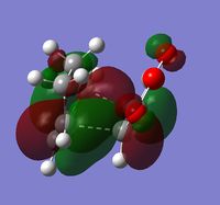
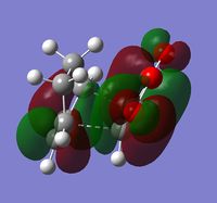
The HOMO and LUMO of the reactants and transition states are shown below:
| Maleic anhydrise HOMO | Maleic Anhydride LUMO | Cyclohexadiene HOMO | Cyclohexadiene LUMO |
| Exo TS HOMO | Exo TS LUMO | Endo TS HOMO | Endo TS LUMO |
The Diels Alder reaction is favoured by orbital overlap between the HOMO of the diene and the LUMO of the dienophile. Looking at the HOMO for the two transition states, it can be seen that they are made up of the HOMO of the cyclohexadiene and the LUMO of the maleic anhydride. The exo TS HOMO and the endo TS HOMO look quite similar. It would be expected to observe the secondary orbital interactions in the HOMO of the endo structure but there do not seem to be any more significant interactions for the endo structure than for the exo structure. This may be because although of the correct symmetry and energy, the orbitals cannot interact to that extent as the reactant molecules do not approach closely enough. This implies that the secondary orbital effect actually does not have much influence on the endo selectivity in this reaction. An alternative explanation[2] for endo selectivity in the Diels Alder can be decribed by representing the transition state in an asynchronous mechanism as a series of resonance forms which includes a zwitterion. In the endo structure the positive and negative charges are in close proximity and therefore are stabilised compared to the exo product where the charges are not stabilised.
References
- ↑ A. Bondi, J. Phys. Chem., 1964, 68:3;DOI:10.1021/j100785a001
- ↑ J. Sauer, R. Sustmann, Angew. Chem., Int. Ed. Engl., 1980, 19, 779-807;DOI:10.1002/anie.198007791


