Rep:Mod:ll4310 2
==Introduction== [1]
Computational chemistry is an invaluable technique which can be utilised in order to predict and rationalise chemical reactivity. In this project the outcome of three different preicyclic reactions will be rationalised, using computational methods to find lowest energy transition states and starting materials in order to find low energy pathways. Quantum mechanical methods will be used to generate the molecular orbitals for Diels Alder reactions in order to reason the kinetic reaction products.
The Cope Rearrangement
The Cope rearrangement is an example of a [3,3]-sigmatropic rearrangement which occurs via a cyclic, concerted mechanism.

In this section the Cope rearrangement of 1,5-hexadiene will be studied, the mechanism of which is shown on the right. As the rearrangement involves 6 electrons (4n+2 where n=1) it is a thermally allowed reaction using Hoffmann's rules. Due to the structure of the transition state resembling cyclohexane it is possible for the reaction to go via either a boat-like or chair-like transition state; the lowest energy of these transition states can be found and hence the preferred mechanism. It is also necessary to find the lowest energy conformer of the diene reactant/product; the possibility of gauche, antiperiplanar, synperiplanar and anticlinal arrangements about C(3)-C(4) bond means there are many conformations with different energies which can exist, and the comparison of the chair and boat transition states from the lowest energy conformer will give the lowest energy pathway.[2]

Optimisation of Reactants
Due to steric repulsion between the two alkene groups at a torsion angle of 0° and between the alkene group on one carbon with a hydrogen atom on the adjacent carbon at a torsion angle of 120° the synperiplanar and anticlinal conformers are highest in energy and therefore wont be considered when looking for the lowest energy conformer; these are not stable enough to exist and are an energy maximum on C-C rotation. There are
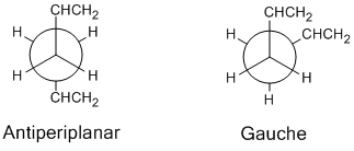
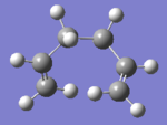
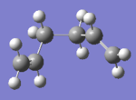
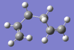
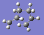
6 gauche and 4 antiperiplanar arrangements which can be optimised to their lowest energy which were considered in this experiment. Optimisation calculations were performed on the ten conformers using the Hartree-Fock method with the 3-21G basis set, giving the following ground state energies of the structures:
From here it was found that the 'gauche 3' conformer was the lowest in energy, with the next lowest being 'anti 1' and 'anti 2' respectively. However, applying a higher level basis set, meaning that more mathematical functions were used to model the system, it was found that the ordering of these three was different, giving the following results:
For the second set of calculations a higher level basis set was used which means that more mathematical functions were used to model the system, giving more accurate results.[3] The antiperiplanar molecules are now lower in energy than the gauche conformation; this may be due to the fact that there are more steric clashes for the gauche conformation as the torsional angle between the bulky groups is only 60°, whereas for the antiperiplanar arrangement the groups are 180° away from each other and this large separation in space means that there are no steric interactions between the two alkene groups.
Comparison of the structures:
| Antiperiplanar 1 | Antiperiplanar 2 | Gauche 3 | ||||
| HF/3-21G | DFT/B3LYP 6-31G | HF/3-21G | DFT/B3LYP 6-31G | HF/3-21G | DFT/B3LYP 6-31G | |
| Energy | -231.69260233 | -234.61180013 | -231.69253516 | -234.61170273 | -231.69266121 | -234.61132934 |
| C=C /Å | 1.32 | 1.33 | 1.32 | 1.33 | 1.32 | 1.33 |
| C(2)-C(3)/Å | 1.51 | 1.50 | 1.51 | 1.50 | 1.51 | 1.50 |
| C(3)-C(4) /Å | 1.55 | 1.55 | 1.55 | 1.55 | 1.55 | 1.55 |
| Dihedral Angle/° | 176.9 | 176.6 | 180.0 | 180.0 | 67.7 | 66.3 |
From the table above it can be seen that using a higher level basis set had very little effect on the geometries of the molecules; the C-C bond lengths were all either the same (to 2 decimal places) or within ±0.01Å of one another. This shows that the 3-21G basis set gave a relatively good model of the optimised structures despite being a less complex calculation. The only significant difference between the calculations was the energy, however as the calculations were ran on different basis sets using different mathematical functions the difference between the energies has no significance and energy values obtained from different basis sets cannot be compared.
It was then necessary to carry out a frequency calculation for two reasons; to confirm that the point reached was an energy minimum and to receive the thermochemical data for the molecule to compare with experimental data. For this the optimised molecules from the B3LYP/6-31G* were used, running a calculation under the job type 'frequency' and the same B3LYP method. From the results it was confirmed that the three molecules were at energy minima as all of the vibrational frequencies were positive; as the frequency is the double derivative of the potential energy surface the values should all be positive at the minimum of the potential energy surface which is the potential energy of the optimised (lowest energy configuration) model.
The thermochemistry data was then retrieved for each of the configurations
| Antiperiplanar 1 | Antiperiplanar 2 | Gauche 3 | |
|---|---|---|---|
| Electronic + Zero Point Energy /HF | -234.469285 | -234.469212 | -234.468693 |
| Electronic + Thermal Energy /HF | -234.461964 | -234.461856 | -234.461464 |
| Electronic + Thermal Enthalpy /HF | -234.461020 | -234.460912 | -234.460520 |
| Electronic + Thermal Free Energy /HF | -234.500163 | -234.500822 | -234.500105 |
The first energy value in the table shows the electronic energy plus the zero point energy contribution due to the vibrational energy of a molecule at 0K. The second values show how thermal energy contributes to the energy of the molecule at 298K, as thermal energy causes the molecule to vibrate, as well as to rotate and translate through space, increasing its energy and hence making it less stabilised. The third value contains an enthalpic contribution which also destabilises the molecule and the fourth value contains a contribution due to the Gibbs free energy of the molecule, which is also temperature dependent, hence it can be seen that temperature has a destabilising effect on the energy of a molecule due to the three extra contributions shown above.
The optimisations were also all ran at 0K to see how this would change the energies in the table above, and it was found that for all four of the energies the calculation gave out the 'Electronic + Zero Point Energy' value, confirming that the other three destabilising contributions were due to effects of temperature. An example of the log files for these calculations follow.
Media:Ll4310 DIENE APP1 321G 0K.LOG Media:Ll4310 DIENE APP2 321G 0K.LOG Media:Ll4310 DIENE GAUCHE3 321G 0K.LOG THE LOG FILES
Optimisation of Transition State
As the boat and chair transition states both contain two C2H5 positioned in certain configurations it was necessary to first optimise the C2H5 fragment before building the transition state structures. This was done by running an 'optimisation' job using the HF/3-21G theory level. The boat structure was then built by positioning two of these 2.2Å apart each with the middle carbon atom pointing up, and the chair in the same way but with the middle carbon of one fragment pointing up and the other pointing down. The optimisation to a transition state for the chair was then done using two different methods.
Optimisation of the chair TS
The first was by computing the force constant matrix for the transition state in the first step of the optimisation, which required a relatively close 'guess' of the structure to the actual structure in terms of geometry. The force constant matrix is the double derivative of the energy so at the maximum point of a reaction co-ordinate (the transition state) it would have a minimum value, with positive values for the rest of the reaction co-ordinate. Hence if the guessed transition state structure was close enough to the actual transition state, and hence the slope of the potential energy curve of the reaction co-ordinate was relatively flat, then the optimisation could be ran until a negative value of the double derivative of the slope was reached.[4] The calculation was performed using the HF/3-21G level of theory. The 'Opt+Freq' job type was ran, this time using the method 'optimise to a transition state (Berny)', with force constants calculated once and the additional keywords opt=noeigen inserted to stop the calculation from crashing if the guess wasn't close enough to the true structure and more than one minimum value was found. The job gave the chair transition state with the imaginary vibration state at 818 cm-1 shown on the right

. The 'vibration' corresponds to the bond making/breaking step and is therefore a good representation of the transition state. The vibration is imaginary and hence negative again due to the vibrational frequency being a double derivative of the potential energy of the reaction co-ordinate, and hence where the slope is at a maximum (at the transition state) the first derivative is equal to zero and the second derivative is negative. This shows the transition state was found successfully.
The second method for the chair transition state optimisation was done by freezing the reaction coordinate and optimising the structure to a minimum. The molecule was then optimised to a transition state starting from this optimised structure, now with the reaction coordinate unfrozen, by differentiating along the reaction coordinate until the maximum point (the transition state) was found, where the differential would be equal to zero. The guessed chair template was again used, with the two allyl C25 fragments placed approximately 2.2Å away from each other and the 'bonds' frozen between the terminal carbon on one fragment to the terminal carbon on the end of the other fragment, which was repeated for the other end of the fragments using the Redundant Coordinate Editor. An 'optimise to a minimum' job was then ran using the HF/3-21G method type to give the optimised ground state geometry. This was then unfrozen so that the molecule could be optimised to a transition state and the distance between the two fragments would no longer be fixed to around 2.2Å. This was done again using the Redundant Coordinate Editor, and where previously the bonds were frozen, the selection 'Derivative' was chosen from the drop down menu for the same two bonds between the fragments. A new calculation was set up, under the job type 'optimise to a transition state' but this time the force constants were not calculated during the optimisation, as the job was set up to differentiate along the bond co-ordinate until the transition state bond length was found.
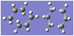
From the image on the left differences between the optimised ground state molecule and the transition state can be seen, particularly between the distances between the two fragments; for the ground state structure the distance between fragments was frozen to 2.17Å - after the transition state optimisation the distance became 2.02Å, the distance at which the bond breaking between two carbon atoms at one end of the fragments and bond formation at the other end would occur in the Cope rearrangement.
Comparisons between the two optimisation methods can be made by comparing the geometries of the resulting optimised transition states, a summary of which is in the following table:
| Computing Force Constants Method | Frozen Coordinates Method | |
|---|---|---|
| Energy | -231.61932234 | -231.61932211 |
| Distance between terminal C atoms/Å | 2.02 | 2.02 |
| C-C Bond Distance/Å | 1.39 | 1.39 |
| Dihedral angle between the two fragments/° | 55.0 | 55.0 |
It can be seen that using either of the methods discussed gives transition state structures with the same geometries, as the distance between the fragments are the same as well as the lengths of the C-C bonds, all to two decimal places. The results show that the C=C double bonds were delocalised over the whole structure in the transition state, as the bond lengths were all equal so all had equal amounts of electron density between them and were all at an intermediate between C-C single (1.53 Å) and C=C double (1.34 Å) bond lengths [5], hence the pi electrons were evenly distributed between the p orbitals on all the carbon atoms. The only difference between the two methods were the energies obtained, however when these were converted to kcalmol-1 the energies only differed by 0.00014 kcalmol-1, which is very insignificant, especially using a simple basis set, and this difference falls within the error of the basis set energy. Theerefore the results obtained using either of the methods are indistinguishable and either method can be used for optimisation.
Optimisation of the boat TS
For the optimisation of the boat transition state the QST2 method was used, where the reactant and product are both entered into a Gaussian calculation and the program converts between the two structures to find the transition state between them. The Ci conformer was used for this step, two of the molecules were added to the same MolGroup so that the calculation could be ran on them at the same time. The reactant and product were numbered so that the carbon atoms corresponded to where, for example, carbon 1 would be in the reactant and the product after it had rearranged as follows (the hydrogen atoms were also numbered appropriately):
An 'Opt+Freq' job type was then set up and now optimisation to a transition state (QST2) was selected rather than running the Berny job type with the aim of obtaining the boat transition structure. However, the calculation output gave the chair transition state structure retrieved from the following .log file, due to the fact this transition state could simply be generated by translation of half of the allylic chain of the reactant/product. Rotation around the C(3)-C(4) bond would be required in the reactant and product so that the interconversion would go through the boat transition state during the Gaussian calculation. Again the carbon and hydrogen atoms were labelled appropriately so that the atoms matched up on the reactant and product. The molecules were modified by setting the dihedral angle for C(2)-C(3)-C(4)-C(5) to 0° and the angles C(2)-C(3)-C(4) and C(3)-C(4)-C(5) were set to 100° to give configurations which resembled the boat transition state, only with no bond between C(1) and C(6) and a bond between C(3) and C(4) rather than partial and equal bonding character between the two. An image of how the diene was modified and its similarities to the boat transition state geometry before the structure was optimised to a transition state follows: 
The same calculation was then performed on this molecule; the job type 'opt+freq' was chosen selecting 'optimise to a TS (QST2)'. This time the output gave the boat transition state with an imaginary frequency at 840cm-1, the negative value of which confirmed that a maximum on the reaction coordinate, confirming that this was the transition state. Also, the vibrational mode resembled the formation of one C-C σ bond whilst another C-C σ broke, as would be expected for the transition state of this Cope rearrangement, as was also present for the chair transition state.

This example shows the downfalls and advantages of all three methods used to optimise the transition states. The Berny method used for the chair required the input of a geometry close to the transition state before the optimisation could be successfully performed, whereas the QST2 generated the transition state by simply inserting the reactant and product and allowing the program to find the transition state from interconversions between the two. However, for the QST2 method if the beginning and end geometries were not close enough to the required transition state the calculation can go wrong, hence it has no real advantage over the first two methods.
From the output files differences in the geometries can be used to determine which transition state would be likely to be more stable. From bond structures the C-C bonds were found to all be the same length, at 1.39Å for the chair and 1.38Å for the boat, hence there was very little difference in the structures here. The bond lengths were at an intermediate between single and double bond lengths [5] due to the redistribution of pi electron density around the structure in the Cope rearrangement. The more significant difference between the structures was the distance between the terminal carbon atoms on each fragment; 2.02 Å for the chair compared to 2.14 Å for the boat. This shows that the σ bond formation was at a more advanced stage for the chair transition state, and this greater interaction between the two fragments may have given the molecule more stabilisation energy, therefore lowering the energy of the transition state. The actual energies of the two transition states can also be compared, and these will be discussed in the following section.
Media:Ll4310 CHAIR FROZEN DERIVATIVE.LOG Media:Ll4310 CHAIR GUESS TSOPT+FREQ.LOG Media:Ll4310 BOAT INPUT MEANTTOWORK.LOG
Intrinsic Reaction Coordinate
It was then possible to work out which conformers of 1,5-hexadiene formed the chair and boat transition states using an Intrinsic Reaction Coordinate (IRC) computation, which allowed the minimum energy path from the transition state to the ground state minimum on the potential energy surface to be traced. The 'IRC' job type was ran on the optimised transition state structures' checkpoint files. It was chosen to compute the IRC in the forward direction as the system was symmetrical (the reactant and product would have the exact same energy), to compute the force constant at every point and to calculate 50 points along the IRC. For the boat geometry the molecule reached a minimum geometry in 45 steps, and in 44 steps for the chair.
From the IRC results it is possible to work out the activation energy for the reaction (the difference in energy between the ground state molecules and the transition state) and hence determine whether the reaction goes via the chair or boat transition state, as the lowest energy pathway will dominate to give the kinetic product, as the reactants can get over the lower energy transition state more quickly, meaning that this product will be formed fastest and will therefore dominate. The activation energies obtained from the calculations will be discussed in the following section.
It is also possible to see which conformer is used to generate which transition state using the IRC ouput, as the output allows you to visualise the reaction pathway taken by the ground state molecule to the transition state.


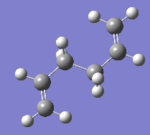
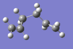
The clips on the right show the path taken by the molecules to the transition state structure, and it is possible to freeze the clips at the lowest energy points which correspond to this structure. The following table shows the ground state structures viewed down the central C-C bond from this IRC calculation and the Newman projections obtained from suitable rotation about this C-C single bond to determine the possible conformers which gave the products from the three lowest energy configurations derived earlier:
| Transition State | Structure of Transition State | Newman Projection of Possible Conformer | Identity of Conformer |
|---|---|---|---|
| Boat |  |
  |
Gauche 3, App 2 |
| Chair | 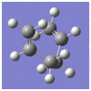 |
 |
App 1 |
For the boat conformation rotation about the central C-C bond of the diene by 60° gives the gauche 3 conformation discussed earlier, and rotation by 180° gives the antiperiplanar 2 conformer. Using the basis 6-31G* basis set it was found that the app 2 conformer was 0.24 kcalmol-1 lower in energy than the gauche conformer, therefore taking the lowest energy pathway it is likely that the antiperiplanar will be the starting conformer for the lowest energy reaction pathway. However, rotation through 180° means that the conformer has to pass over an energy maximum due to a anticlinal intermediate on the rotation reaction coordinate, whereas the gauche conformer only has to rotate 60° to form the low energy starting conformation shown in the table, with no energy maxima needed to be overcome on the rotation reaction coordinate and hence no unfavoured intermediates. It is therefore difficult to predict whether the reactant would be likely to start as the antiperiplanar form or the gauche form.
For the chair conformation only the antiperiplanar 1 conformer discussed earlier is a suitable low energy starting material for the reaction co-ordinate, and the starting material is generated by 180° rotation about the central C-C bond, again having to pass over an energy maximum on the rotation reaction coordinate.
To compare the activation energies the transition states next had to be optimised to a higher basis set for more accurate calculations. The chair and boat transition states were optimised to a transition state using the Berny job type, using the B3LYP/6-31G* method. From this the energies of the transition states and the ground state geometries could be compared. The following table shows the energies given:
| Chair TS | Boat TS | App - 2 | ||||
| HF/3-21G | DFT/B3LYP 6-31G | HF/3-21G | DFT/B3LYP 6-31G | HF/3-21G | DFT/B3LYP 6-31G | |
| Electronic Energy /Hartrees | -231.619323 | -234.556983 | -231.602802 | -234.543093 | -231.692535 | -234.611703 |
| Electronic + Zero Point Energy /Hartrees | -231.466703 | -234.414929 | -231.450932 | -234.402340 | -231.539539 | -234.469212 |
| Electronic + Thermal Energy /Hartrees | -231.461343 | -234.409008 | -231.445302 | -234.396006 | -231.532566 | -234.461856 |
| Structure | HF/3-21G | B3LYP/6-31G* |
|---|---|---|
| Boat | 2.14 | 2.20 |
| Chair | 2.02 | 1.97 |
From the comparison of geometries table it can be seen that optimisation to a higher basis set altered the structures of the transition states significantly. The higher basis set works by using more functions to carry out the calculation giving a better representation of the reactants and transition state, hence the results from the B3LYP/6-31G* should give a better representation of the transition state. It can be seen that the higher level basis set gave a boat structure with a greater interfragment distance than the HF/3-21G set (2.20 Å compared to 2.14 Å) whereas the chair transition state had a shorter interfragment distance for the B3LYP/6-31G* than the lower level basis set. This shows further that the chair transition state is the dominant pathway, as the shorter interfragment distance shows that there is more bonding character between the two fragments for the chair transition state than for the boat, and this additional C-C interaction may stabilise the molecule lowering the energy of the transition states.
From the energies it can be seen that the chair transitions state is the lowest energy of the two using both basis sets, hence this is the preferred pathway. 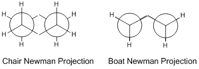 This is calculated by working out the difference in energy between the starting material and the transition state. When the values are converted to kcalmol-1 at 298K the difference in energy between the app-2 conformer and the chair transition state is +44.7 kcalmol-1 for the 3-21G basis set and +33.2 kcalmol-1 for the 6-31G* basis set. For the boat transition states these energy differences are much greater, with +54.8 kcalmol-1 for the 3-21G basis set and +41.1 kcalmol-1 for the higher level basis set. It can be seen for the higher level basis set that the energy differences between the reactants and transition states is lower; this is due to more accurate calculation due to more complex mathematical functions used. The reason why the boat transition state is higher in energy can be seen from the Newman projections on the left. For the chair transition state all of the C-H and C-C bonds are completely staggered looking down the interfragment C-C bonds, whereas for the boat all of the C-C and C-H bonds are completely eclipsed. This means that there are more steric clashes in the boat configuration, destabilising the transition state and hence increasing its energy. For the chair configuration these steric clashes are not present hence the structure is more stable and lower in energy.
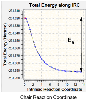
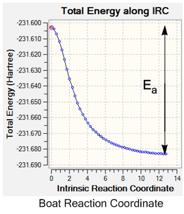
The activation energy during the reaction could also be determined from the IRC output, using the reaction co-ordinate graph. These plot the pathway taken from the transition state to the lowest energy reactant, hence by reading off the energy difference between the two and converting to kcalmol-1 the activation energy for the reaction can be determined.
In order to determine which of the transition states had the lowest activation energy and was therefore the dominant pathway in the Cope rearrangement it was necessary to run the optimisations at a higher basis set, and again run an IRC so that the difference in energy of the ground state reactants/products (as the system is symmetrical) and the energy of the transition state could be found.
| Structure | HF/3-21G | B3LYP/6-31G* | Experimental Value (B3LYP/6-31G*) |
|---|---|---|---|
| Boat Activation Energy /kcalmol-1 | +50.2 | +37.7 | 44.7 ± 0.2 [1] |
| Chair Activation Energy /kcalmol-1 | +45.8 | +33.8 | 33.5 ± 0.5 [1] |
From the IRCs the activation energy of the reactions could be determined by finding the difference in energy of the ground state molecule and the transition state, as is shown on the graphs above, and IRC calculations were ran at both basis sets. Again for the two different basis sets different values were found for the activation energy; the higher level B3LYP/6-31G* set gives a smaller value for both of the transition states. This may be due to the calculation containing more mathematical functions, hence overestimating the energy less to give a more accurate value. This increase in accuracy can be seen on comparison of the chair calculated value with the experimental value, which is within the error limit of the experimental data and hence is a good approximation. However, for both of the basis sets the calculated boat activation energy is inaccurate; both of the values are out by up to 8 kcalmol-1. This may be due to the requirement of rotation around the central C-C bond of the aap-2 structure into the correct confirmation for the boat transition state to be formed, whereas this is not necessary for the chair transition state, giving an experimental activation energy for the boat activation energy which is higher than the calculated value.
The Diels Alder Cycloaddition
The Diels Alder reaction is an example of a pericyclic cycloaddition reaction involving 6 π electrons; 4 from one molecule (the diene) and 2 from the other (the dienophile), where the π orbitals are used to form two new σ bonds between the two molecules and one new π bond. As there are 4n + 2 electrons involved in the concerted, cyclic reaction mechanism (n = 1) the reactions are thermally allowed using Hückel's rule. The reaction involves interaction of the HOMO/LUMO of the diene with the HOMO/LUMO of the dienophile so long as the molecules are of the correct symmetry. If the symmetry of the HOMO/LUMO of the two molecules is different there is no overlap between the two and therefore no interaction; a new σ bond cannot be formed. This section will look at two Diels Alder systems, one simple reaction between butadiene and ethene and a slightly more complex reaction between a substituted dienophile, maleic anhydride, and cyclohexa-1,3-diene, where the regioselectivity will be studied and rationalised by secondary orbital interactions. [2]
Butadiene and Ethylene
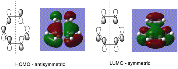
As there are 4 π electrons in the diene and 2 п electrons in the dienophile (4n+2 overall) the reaction is thermally allowed, going via Huckel topology with suprafacial components, hence it is an example of a [4s + 2s] cycloaddition reaction. To confirm that the reaction is allowed, and that the HOMO/LUMO overlap of the two reactants is of the same symmetry, it was necessary to compute the molecular orbitals of butadiene and of the butadiene-ethylene adduct.
To determine the symmetry of the HOMO and LUMO of butadiene the molecule first had to be optimised. The butadiene fragment was built in GaussView, and a calculation was ran under the job type 'optimisation'. The semi-empirical AM1 method was used to optimise the molecule to a minimum. The semi-empirical method uses quantum mechanical techniques and therefore can be used to model electronic interactions and molecular orbitals and hence is useful for the Diels Alder symmetry calculations. The HOMO and LUMO of the diene were then visualised from the checkpoint output file, giving the molecular orbitals shown on the left.
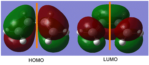
From this it can be seen that the HOMO is anti-symmetric with respect to the plane of symmetry (shown in orange) as reflection on this plane changes the phase of the orbitals. The LUMO can be seen to be symmetrical with respect to the plane, as reflection causes no change in phase. For successful reaction with ethylene it is essential that the ethylene LUMO is anti-symmetrical and the HOMO symmetrical, as the Diels Alder cycloaddition involves HOMO/LUMO interactions which must be of the same symmetry. [1]
The symmetry of the transition state structure had to be generated next to determine the structure of the HOMO and LUMO in the transition state and hence determine whether their overlap was successful. A guessed structure for the transition state was drawn using GuassView, with the ethene fragment over the plane of the butadiene fragment. The distance between the two fragments was set to 2.2Å as an approximation. The structure was then optimised using the 'opt+freq' job type on the semi-empirical AM1 method. The structure was optimised to a transition state (Berny) with the force constants calculated once, and the additional keywords 'opt=noeigen' were added so that the calculation would not crash during the frequency calculation if more than one negative frequency was found.
The output gave a structure with a slightly puckered butadiene fragment, and an imaginary frequency at 956cm1 confirming that a maximum on the reaction coordinate and hence the transition state geometry had been reached. Here the imaginary vibration frequency resembled the formation of the two new σ bonds between the π orbitals at the ends of the two fragments, as well as showing the lengthening of the ethene C=C bond, due to partial breaking of the π bond, and shortening of the C-C bond between the middle two carbon atoms of the butadiene fragment due to partial formation of a new π bond in the transition state.

It can be seen that the formation of the two new bonds is synchronous, proving that the reaction goes via a concerted mechanism with the two new σ bonds forming at the same time. Conversely, in the real frequency at 247cm-1 the bond formation step is asynchronous. However it is the imaginary frequency, not this positive frequency, which resembles the transition state, hence overall the step is synchronous and the mechanism concerted.
Next the HOMO and LUMO were visualised using the checkpoint output file. The resultant molecular orbitals are shown in the image below, with a sketch showing the 6 p orbitals involved in the formation of the two new σ bonds and the π bond. It can be seen that the HOMO is antisymmetrical with respect to the plane of symmetry and the LUMO symmetrical. As the HOMO of butadiene was determined to be antisymmetrical this shows that the LUMO of ethylene is antisymmetric, to give successful HOMO/LUMO overlap and likewise the HOMO of ethylene was symmetric to give successful overlap with the symmetrical butadiene LUMO to form the symmetrical antibonding orbital. This proves that the reaction goes by an allowed mechanism, as this requires orbitals to be of the same symmetry to overlap and form a new bonding orbital, and here two antisymmetrical orbitals overlapped to form the bonding orbital and two symmetrical orbitals overlapped to form the antibonding orbital. It also shows that this Diels Alder reaction goes by normal electron demand; the electrons are donated from the HOMO of the electron rich diene to the LUMO of the electron poor dienophile (ethylene) to form a new bonding orbital.
A summary of the geometry of the transition state is in the following table:
| Interfragment C-C Bond Length/Å | 2.12 |
| Ethene C-C Bond Length/Å | 1.38 |
| Butadiene C(1)-C(2)/C(3)-C(4) Bond Length/Å | 1.38 |
| Butadiene C(2)-C(3) Bond Length/Å | 1.40 |
As the interfragment C-C bond length is the same at each end of the two chains it can be confirmed that the reaction goes via a cyclic concerted mechanism; if the two C-C σ bonds did not form at the same time the two lengths would be different. The distance also confirms that new σ bonds are being formed. A typical value of the van der Waals radius for carbon is 1.70 Å. As the C-C interfragment distance of 2.2Å is much shorter than the sum of the van der Waals radii there is interaction between the two nuclei showing that bond formation is occurring between the two. Redistribution of the electrons around the butadiene fragment is also evident. A typical C=C length is 1.34 Å. In the transition state structure the two bonds which were originally double bonds have lengths of 1.38 Å, showing that these bonds have lengthened slightly, losing some of their double bond character. The same lengthening effect can also be seen in the ethene fragment. The C(2)-C(3) bond, conversely, experiences a degree of shortening. A typical C-C single bond length is 1.53 Å. However this C-C length has significantly reduced to 1.40 Å, showing that it has gained π bonding character. This geometry can be rationalised by the mechanism. Head on overlap between the p orbitals on the end carbon atoms on the diene with the p orbitals on the ethene fragment begins to form two new σ bonds between the fragments, reducing the distance between the fragments while reducing the π electron density in the original π bonds. The two remaining p orbitals on butadiene's middle two carbons are then able to overlap with one another in a side-on fashion and begin to form a new π bond, hence the C-C bond begins to shorten.[5]
TS IRC guessed transition state
Cyclohexa-1,3-diene and Maleic Anhydride
The Diels Alder reaction between substituted dienes and dienophiles are slightly more complex than the above example as regioselectively has to be taken into account, in terms of which way round the fragments join giving either exo or endo products. In this section the relative energies of the two products will be compared to determine which is more likely to form. The diene in this example will be cyclohexa-1,3-diene, where the ring system locks the diene into the cis configuration required for the Diels Alder reaction. The dienophile used will be maleic anhydride; here three electron withdrawing oxygen atoms pull electron density out of the C=C double bond, making it very electron deficient encouraging the reaction to occur.
First the two fragments had to be optimised. The maleic anhydride and the cyclohexa-1,3,-diene were built separately and on each an optimsation to a minimum was performed using the semi-empirical AM1 method to give the ground state reactant molecules. Then the guessed structures of the exo and endo transition states were built, as shown on the right.
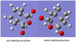
For the exo structure the double bond of the maleic anhydride was placed above the ends of the double bonds on the hexadiene structure with the oxygen atoms facing away from the double bonds, whereas in the endo structure the maleic anhydride was oriented with the oxygen atoms situated above the double bonds of the hexadiene molecule. The interfragment distances were frozen using the 'Redundant Coordinate' tool to approximately 2.2Å, and an optimoisation to a minimum job was ran using the semi-empirical AM1 method. This gave two ground molecules which were slightly puckered in the region where the new σ bonds would be formed. The coordinates were then unfrozen and an 'opt+freq' job was ran on each system, selecting the 'optimise to a TS (Berny)' job type on the semi-empirical AM 1 method, using the additional keywords 'opt=noeigen'.
For the exo transition state the output gave an imaginary frequency at 812 cm-1, showing that it was fully optimised to a transition state.
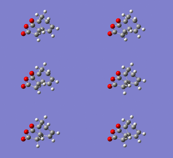
It can be seen from the image on the left that again the vibration resembled the σ bond formation between the two π systems. Again lengthening of the π bonds can be seen while the two new σ bonds are formed, and the shortening of the σ bond between the two π bonds on the hexadiene where the new bond will be formed in the product. The formation of the two bonds is again synchronous, showing that the mechanism ran in a concerted fashion with both bonds forming at the same time.
For the endo transition state the output gave an imaginary frequency at 806 cm-1, showing that this was also fully optimised to a transition state.
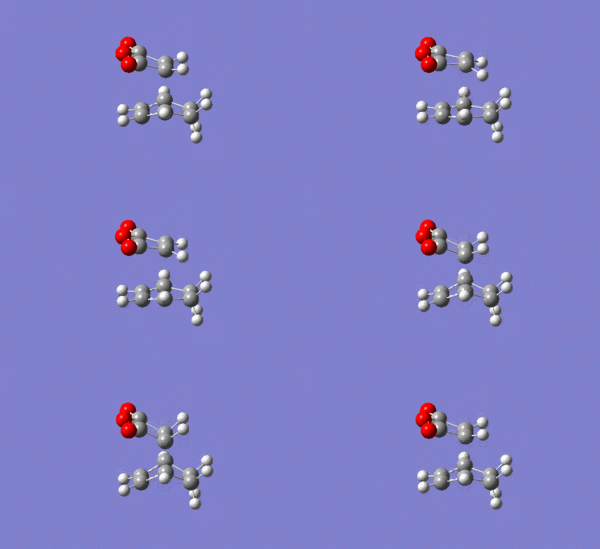
As shown on the right, again the vibration resembled the σ bond formation step between the two fragments with lengthening and shortening of appropriate bonds. Again the bond formation is synchronous, agreeing with the cyclic, concerted transition state of the Diels Alder pericyclic cycloaddition.
The geometric properties and the energies of the two transition states are summarised in the following table:
| Parameter | Endo | Exo |
|---|---|---|
| Energy /Hartree | -0.05150480 | -0.05041985 |
| Energy /kcalmol-1 | -32.3 | -31.6 |
| Maleic Acid C=C Length /Å | 1.41 | 1.41 |
| Hexadiene C(1)=C(2)/C(3)=C(4) Length /Å | 1.40 | 1.39 |
| Hexadiene C(2)-C(3) Length /Å | 1.40 | 1.40 |
| Interfragment distance | 2.16 | 2.17 |
From the table above it can be seen that the two transition states are very similar in their geometry; all bond distances are equal within ±0.01 Å and there is only a difference in the interfragment distance of 0.01 Å, hence only a very small difference in the extent of orbital overlap between the reactants. This accounts for the very small difference in the energy of the transition states; 0.7 kcalmol-1. However, the endo transition state can be seen to be the lower in energy and hence more stable of the two transition states, and the reasons for this can be seen by looking at the molecular orbitals and considering the additional overlap of the oxygen lone pairs with the carbon p orbitals, as will be discussed. However the activation energy must also be considered to see which route is kinetically favoured, which also depends on the ground state energy of the reactants.
To find out the activation energy of the reactions an IRC reaction was ran on both of the transition states. This was done by running the job type 'IRC' in both directions, with the force constants calculated 'always' and running 120 steps. The images on the right show the simulations of the exo- and endo- intrinsic reaction co-ordinates, and the activation energies and free energies of reaction were calculated from the graph which follow.

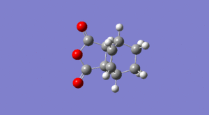
| Parameter | Endo | Exo |
|---|---|---|
| Activation Energy /kcalmol-1 | +26.7 | +28.2 |
| ΔG /kcalmol-1 | -41.5 | -40.5 |
From the table it can be seen that the activation energy for the endo- transition state is the lowest in energy, hence the kinetic barrier for this reaction route is lower and the endo- product is formed; this is the kinetic product. It can also be seen that the endo- product has the lowest energy as this reaction has the more negative change in Gibbs Free Energy, hence the endo- product is the thermodynamic product as well. One reason why the endo product forms more readily is due to secondary orbital overlap, where the p orbitals on the C=O carbon atoms from the maleic anhydride interact with the p orbitals on the C=C of the hexadiene, stabilising the transition state hence lowering its energy, and as the lowest energy reactive pathway is kinetically favoured this route is taken to give the endo product as the major kinetic product. This will be discussed further in the following section where the molecular orbitals will be generated. The reason why the endo product is also thermodynamically favoured is due to steric clashes in the exo product.
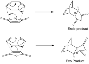
As can be seen from the image on the right, in the endo product cis addition to the bottom face of the diene causes the maleic anhydride to be pointing downwards, leaving two hydrogen atoms pointing upwards adjacent to the bridge. When the maleic anhydride is added the opposite way round (to give the exo product) the hydrogen atoms end up pointing 'down' with the maleic fragment pointing upwards adjacent to the CH2CH2 bridge. This generates a sterically crowded product, with the bulky group experiencing steric clashes with the bridge, destabilising the molecule so that the product is of higher energy. This explains why this pathway has a smaller magnitude of Gibbs free energy and hence the exo pathway is less favoured thermodynamically.
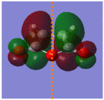
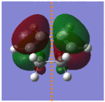
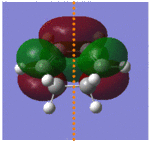
Again to see that the Diels Alder reaction went via an allowed pathway it was necessary to generate the HOMO and LUMO of the maleic anhydride and butadiene. This was done using the checkpoint outputs of the two optimised fragments, generating the molecular orbitals shown below:
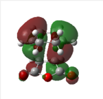
As discussed earlier it is necessary for the HOMO of the diene and the LUMO of the dienophile to have the same symmetry, and vice versa. From above it can be seen that this requirement is fulfilled for this system; the HOMO of the diene and the LUMO of the dienophile are both antisymmetrical. The maleic anhydride C=C is extremely electron deficient due to the electron withdrawing effects of the three oxygen atoms, meaning that this reaction will go by normal electron demand, with electrons donated from the HOMO of the diene to the LUMO of the maleic anhydride fragment. The overlap of two antisymmetric orbitals must give an antisymmetric bonding molecular orbital in both products; this is fulfilled and the antisymmetric HOMO of the exo and endo products can be seen in the table below. The table below shows interesting results for the LUMO, however. As the remaining HOMO of the maleic anhydride and the LUMO of the hexadiene are symmetrical these would be expected to overlap to form a symmetrical antibonding orbital. However, both the endo and exo transition states had antisymmetrical LUMOs. It can be seen from the table of reactant MOs above that due to the highly electron withdrawing effects of the oxygen atoms the HOMO is very low in energy, with an energy of -0.44187 Hartrees compared to the high energy of the hexadiene LUMO, which has an energy of 0.01692 Hartrees. The energy gap between these two orbitals is too large for successful interaction to occur and therefore the symmetrical bonding orbital cannot be formed between the two of them. Therefore HUMO/LUMO overlap is not responsible for the antisymmetric nature of the antibonding orbitals for the exo and endo transition states.
| Endo HOMO | Endo HOMO | Exo HOMO | Exo LUMO | |
|---|---|---|---|---|
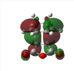 |
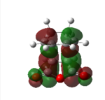 |
 |

| |
| Symmetry | Antisymmetrical | Antisymmetrical | Antisymmetrical | Antisymmetrical |
From analysis of the antisymmetrical bonding molecular orbital it is possible to see the reason for the kinetic stability of the endo product compared to the exo product
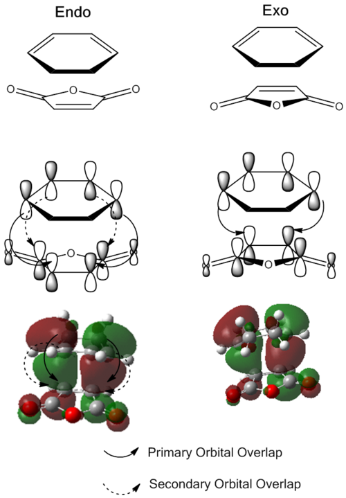
and this is more easily visualised in the following image. For both of the transition structures there is overlap between two carbon p orbitals on one fragment with two carbon p orbitals on the other fragment; these are involved in forming the new σ bond. However, for the endo transition state the p orbital on the carbonyl carbons in the maleic anhydride can interact with the remaining p orbitals on the hexadiene fragment, stabilising the transition state making this one the lower in energy of the two and therefore making the endo product the kinetically more stable product. There is no such interaction for the exo product as the carbonyl groups are pointing in the opposite direction and are therefore in the wrong orientation to overlap.
Endo opt+freq to a TS Endo IRC TS guess file Exo opt+freq to a TS exo IRC
Conclusion
In conclusion it is possible to use computational chemistry in order to find lowest energy reaction pathways and to determine the major product of a reaction if more than one product can be formed. It is also possible to compare transition state structures using quantum mechanical semi-empirical methods in order to visualise molecular orbitals involved in transition states, and then use these to rationalise results, such as the reasoning for the preference of the endo product in the Diels Alder reaction discussed. These simulations provide a good approximation comparable to experimental values and overall are a useful technique in rationalising chemical reactivity.
References
<references> [2] [3] [4] [5] [1] </reference>
- ↑ 1.0 1.1 1.2 1.3 1.4 M. Bearpark, https://wiki.ch.ic.ac.uk/wiki/index.php?title=Mod:phys3#Optimizing_the_.22Chair.22_and_.22Boat.22_Transition_Structures, 2012. Last date accessed: 07/12/2012.
- ↑ 2.0 2.1 2.2 H. Rzepa, Pericyclic Reactions, 2nd year Imperial College London lecture course, 2012.
- ↑ 3.0 3.1 P. Hunt, http://www.huntresearchgroup.org.uk/teaching/year3_lab_start.html, 2012. Last date accessed:07/12/2012.
- ↑ 4.0 4.1 IUPAC website http://old.iupac.org/reports/1999/7110minkin/h.html, 2012. Last date accessed 07/12/2012
- ↑ 5.0 5.1 5.2 5.3 W. M. Haynes, CRC Handboook of Chemistry and Physics, 2012-2013, 93th ed., p.9-48.

