Rep:Mod:hlj298
Study of the reaction profiles of the Cope Rearrangement and the Diels-Alder Cycloadditions
Y. L. J. Lam
Department of Chemistry, South Kensington Campus, Imperial College London, London SW7 2AZ, United Kingdom
Received 18 December, 2015
Abstract
The reactants, products and transition states of the Cope Rearrangement of 1,5-hexadiene were investigated by GaussView 5.0 at the HF/3-21G and B3LYP/6-31G*levels of theories respectively. With that, the point groups, vibrational frequencies and different energies at different temperatures of the reactants, products and transition states were calculated. Also, by optimizing the transition structures with different methods, i.e. computing the force constants at the beginning of the calculations, using the redundant coordinate editor and QST2, at the HF/3-21G level of theory, closer views of the geometries of the transition states can be observed. Furthermore, by using the IRC method, the reaction profiles can be obtained and the activation energies can therefore be calculated. Plus, using IRC method, all reaction intermediates can now be observed, which helps us to understand the mechanism of the Cope Rearrangement. Similarly, for Diels-Alder Cycloadditions between ethene and butadiene and Diels-Alder Cycloadditions between cyclohexa-1,3-diene and maleic anhydride, the reactants, products and transition states were optimized and their respective energies were calculated at AM1 semi-empirical molecular orbital method. Furthermore, the symmetries of the molecular orbitals were visualized and the reaction profiles calculated by IRC method were obtained.
Introduction
Chemical reactions are happening around the world in every second. Some reactions are fast, whilst some are slow. The most common and general reason for that is on the kinetic and thermodynamic aspects. On the kinetic aspect, we might argue that the energy barrier(s) form the reactant(s) to the product(s) is/are huge, and therefore, the reactant(s) cannot overcome the barrier(s) and the reaction is slow or does not proceed. The transformation between crude carbon and diamond is a good example. The energy difference between crude carbon and diamond is just few kcal/mol, however, the energy barrier for the transformation is huge. Hence, the transformation is extremely slow, or even does not proceed. With that, diamond symbolizes eternity. On the other hand, on the thermodynamic aspect, we might argue that the reaction is endothermic, i.e. absorbing/requiring heat from the surroundings in order to proceed. In fact, these two aspects just provide us with a little bit of the story and therefore, chemists, or scientists in general, study the mechanism of the reactions to find out the full story. Unfortunately, some reactions are spontaneous, such as the thiocyanation of the iron complex. Also, some intermediates of the reactions are unstable, which cannot be separated or detected even using very advanced analytical instruments, such as nuclear magnetic resonance (NMR) spectromenter. Therefore, scientists devised some programs and computational methods to find out the mechanism of the reactions. Here we use GaussView 5.0 for our investigation.
Nf710 (talk) 19:30, 17 January 2016 (UTC)Very nice intro using real world examples
Computational Theory
In GaussView 5.0, there are numerous methods for calculation, such as HF/3-21G, B3LYP/6-31G*, semiempirical AM1, MP4 and MP2. Here, the first two calculation method, namely, HF/3-21G and B3LYP/6-31G* were applied for calculation of the Cope Rearrangement Reaction, while semiempirical AM1 was used for the investigation of the two Diels-Alder reactions.
N.B. No matter which method applied, the RMS Gradient Norm in hartress would also be computed. This is a measure of how well does the optimisation go during the calculation of the structure drawn. The closer to zero, the better the structure is optimised.
Hartree-Fock (HF) Method
Hartree-Fock theory (HF) is the fundamentals of electronic structure theory. It gives a good starting point for more elaborate theoretical methods which can approximate the electronic Schrödinger equation better. It is the basis of the molecular orbital (MO) theory that assumes the motion of each electron can be described by a single-particle function/orbital and it does not depend on/interact with the instantaneous motions of the other electrons.[1]
Becke, 3-parameter, Lee-Yeang-Parr (B3LYP) Method
Beeke, 3-parameter, Lee-Yang-Parr (B3LYP) is one of the most commonly used hybrid functionals. Hybrid functionals are a class of approximation of the exchange-correlation energy functional in density functional theory.[2] B3LYP contains an HF exchange with the weight of 0.2, which can be regarded as a uniform screening of exchange by 80 %.[3] B3LYP also takes a set of atomization and ionization energies, proton affinities and total atomic energies into account.[4]
Semiempirical Austin Model 1 (AM1)
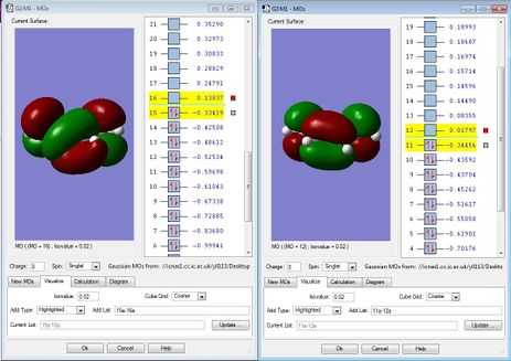
Semiempirical Austin Model 1 (AM1) based on the Neglect of Differential Diatomic Overlap (NDDO) integral approximation.[5] Therefore, when taking the same molecule for AM1 and HF/3-21G, you would find that the numbers of HOMO and LUMO are different, which AM1 gives smaller numbers as shown in Figure 1. This is due to the neglect of the low-lying orbitals overlapping. With that, AM1 proceeds much faster than HF/3-21G for the sake of time.
Nf710 (talk) 19:41, 17 January 2016 (UTC) You have a shown a very high level of understanding here well done.
The Cope Rearrangement
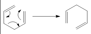
The Cope Rearrangement is an organic reaction involving [3,3]-sigmatropic rearrangement of 1,5-dienes, which resembles the Claisen Rearrangement.[6] The mechanism of the Rearrangement has sparked a controversy – whether it is concerted, dissociative or stepwise.[7] With that, first, each conformer of the reactant, 1,5-hexadiene, was optimised by HF/3-21G. The lowest energy conformer of 1,5-hexadiene was found. Then, as we know, the Rearrangement undergoes either a chair or boat transition state. So, each transition state was optimised by HF/3-21G as well. By looking into the energy difference between the transition states and the reactant, the activation energy of the Cope Rearrangement with 1,5-hexadiene was found. In order to find the reaction profile and see how the 1,5-diene rearranges, i.e. the mechanism, the transition state was optimised again with mainly two methods. The coordinate of the chair transition state was first frozen, with the bond to be made set as 2.20000 Å. 2.20000 Å is a good bond length for partially C-C bond as suggested by the chemists’ observations in the literature. [8] Then, after the optimization of the frozen coordinate, the partly form 2.20000 Å can be relaxed and the structure was then reoptimised. This methods skips the process of computing the whole force constant matrix i.e. Hessian, which saves time and costs. Furthermore, the boat transition state was optimised by QST2. QST2 has a higher constrains in which requires a more accurate transition state structure to be put in. In this case, the dihedral angle plays an important role in order to be calculated by GaussView 5.0. Hence, this method is more expensive and time-consuming. From the optimised transition states, an IRC can be run for the optimised structure to see the full reaction profile. Also, the intermediates of the reaction can be observed. And finally, the reactant and two transition states were optimised with B3LYP/6-31G* similarly. Hence, the two calculation methods can be compared by looking into the numbers obtained. Also, the numbers can be compared against the experimental values. As explained above, B3LYP takes a more in-depth consideration, the numbers got from this method should be closer to the reality.
The Diels-Alder Cycloaddition
The Diels-Alder cycloaddition is a [4+2] cycloaddition between a dienophile and a conjugated alkene to give a cyclohexane system. Here, calculations on two Diels-Alder cycloaddition reactions are reported. They are (1) ethylene and butadiene and (2) cyclohexa-1,3-diene and maleic anhydride.
For Diels-Alder cycloaddition reaction, it is well-known that the reaction gives exo and/or endo product. Exo product implies the reaction pathway is thermodynamically controlled to give more stable product; endo product implies the reaction pathway is kinetically controlled to give a relatively less stable product. In other words, the activation energy to form the exo product is higher than that of endo, however, the endo product is higher in energy than exo. This can usually be explained by the secondary orbital effects. In our cases, both the exo and endo products were investigated undoubtedly. This time, as you may notice, the molecule is more large in size and there are two reactants instead of just one reactant in the Cope Rearrangement, a simpler method of calculation was implemented, which is AM1. Also, the electronic distributions and orbitals of the HOMO and LUMO of the transition states were computed and visualised.
Computational Method
All calculations were performed by GaussView 5.0. Relevant JSmol files were uploaded here, however, due to some technique glitches, some bonds, especially double bonds, might not come up properly. Yet, the structures of the molecules are generally correctly shown.
The Cope Rearrangement
An anti and gauche conformation of the 1,5-hexadiene were drawn respectively. The drawn structures were first optimised by a not very accurate technique, i.e. Clean. Then, the cleaned structure were optimised by HF/3-21G. The point group and the energy of each conformer were found and compared to locate the low-energy minima. The optimised structures from HF/3-21G were then reoptimised by B3LYP/6-31G*. The point group of each conformer was checked and confirmed. Also, the comparison of the same conformer under different calculation method HF/3-21G and B3LYP/6-31G was carried out by looking into energy, bond lengths and bond angles. Furthermore, the Thermochemistry using job type Frequency was found in both HF/3-21G and B3LYP/6-31G* optimised anti conformers.
The boat and chair transition structures were also drawn and cleaned. The point group of each transition state was found.
Firstly, the chair transition structure was optimised to TS (Berny) in Opt + Freq using the basis of HF/3-21G. Force constant was calculated once. The frequency of vibration was checked to make sure there is one imaginary vibrational frequency. Then, freeze coordinate of the molecule by freezing the carbon-carbon bond to be made as 2.20000 Å. After that, the frozen coordinate was relaxed so the carbon-carbon bond to be made no longer be restricted to 2.20000 Å. The geometry of the transition state was then compared.
Secondly, at the same time, the boat transition structure was optimised by QST2 method by specifying the reactants and products of the reaction under the basis of HF/3-21G. Labelling the atoms in the reactant and product, and adjusting the central C-C-C-C dihedral angle to 0o plus the two inside C-C-C angles to 100o, the reactant and product could now be optimised by QST2 method.
Comparing the optimised chair and boat transition structures, the connecting conformer of 1,5-hexadiene was found. The reaction energy profile was then calculated by IRC under HF/3-21G with 50 points and force constant as always for every small steps. With that, the mechanism of the reaction, as well as the whole reaction energy profile, could be observed clearly. Take the last point on the IRC and run a normal optimisation under HF/3-21G to obtain a minimized geometry.
Eventually, reoptimise the structures of the two transition states with Opt + Freq under the basis of B3LYP/6-31G*. The geometries and energies of the transition structure under two different basis were compared. With that, these computed values were also compared against experimental values.
The Diels-Alder Cycloadditions

Ethylene and butadiene
The structure of cis-butadiene was first optimised under the basis of semiempirical AM1. The HOMO and LUMO of cis butadiene were visualised and its symmetry was determined.
The transition state of the reaction was drawn and optimised under the basis of semiempirical AM1. The IRC was carried out in order to confirm the transition structure postulated is of the correct one. Furthermore, the HOMO of the transition structure was visualised and the nodal planes and properties of the system were interpreted.
Cyclohexa-1,3-diene and maleic anhydride
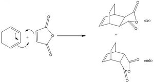
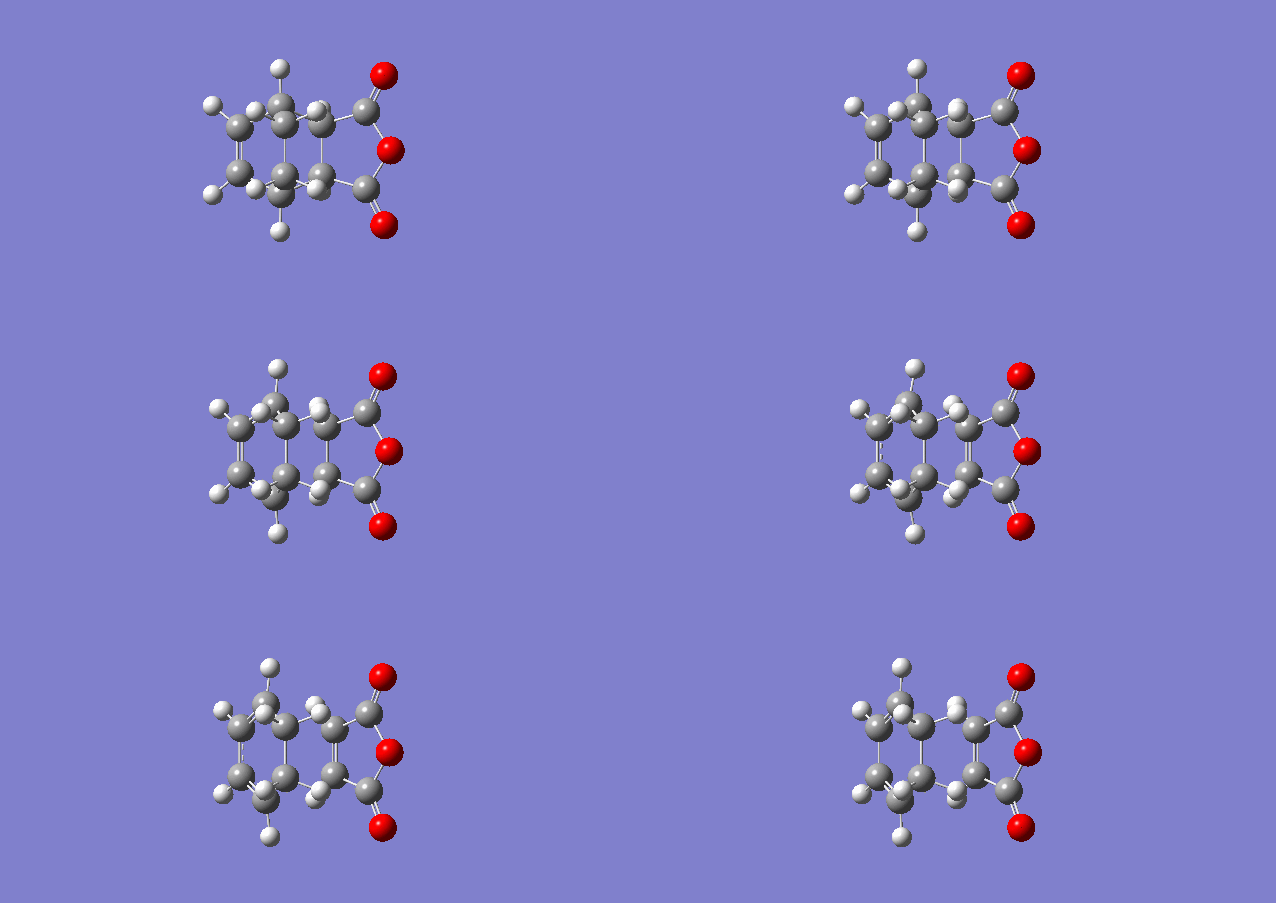
The transition states of the exo and endo products were drawn and optimised under the basis of semiempirical AM1. The IRC was carried out in order to confirm the transition structure postulated is of the correct one. For the number of points, 21 points were used for exo transition states and 24 for endo. This is because the energy was too shallow and the slopes tend to zero after the number of points specified above and GaussView 5.0 cannot predict which direction should it goes on to calculate. Furthermore, the bond lengths, orientation and the HOMO of the transition structures were investigated.
Results and Discussion
The Cope Rearrangement
Optimisation of Reactant
1,5-hexadiene has three free rotating carbon-carbon bonds. Each of them has three rotational minima. This gives 27 conformations of the 1,5-hexadiene molecule. Yet, only ten of them were energetically distinct due to symmetry and enantiomeric relationships.[9] Two of them, the Ci anti and C1 gauche structure in here were drawn and optimizied as shown in Figure A and B and their energies were calculated as shown in Table 1.
*1 hartree = 627.509 kcal/mol
#The difference in energy between the conformer and the lowest energy conformer, in here, which is Gauche3. Then convert Hartree to kcal/mol by *
Table 1. Conformational analysis of anti2 and gauche3 of 1,5-hexadiene
As shown in Table 1, the energy of Gauche3 is surprisingly lower than the anti2 conformation of 1,5-hexadiene. In most cases, the antiperiplanar conformation of a molecule, such as anti2, is more favourable as it has the least steric clashes. Therefore, usually the antiperiplanar conformation is of the lowest energy. However, here, apart from sterics, the stereoelectroncs concept has also been taken into account. The vinyl proton, in a through space manner, can interact with the π or π* orbital on the sp2 carbon which is separated by four bonds from it.[10] This is so-called CH-π interaction. The Newman Projection in Figure 5 gives us a closer look on how they are close in space and interact; and the Newman projection in Figure 6 tells us why the vinyl proton cannot interact with the π or π* system through space. Therefore, the gauche3 conformation is more stable than anti2 and of lower energy in 1,5-hexadiene.
Nf710 (talk) 19:57, 17 January 2016 (UTC) The reference that you got that from is out dated. you could have showns the secondary orbital overlap yourself form the .chk file.
Focusing on anti2 conformer of the 1,5-hexadiene, the HF/3-21G optimised molecule was reoptimised by B3LYP/6-31G. The energies and the geometries of the anti2 1,5-hexadiene under two basis of calculation method were compared and shown in Table 2.

| Calculation Method | Point Group | Energy/ Hartrees | RMS Gradient Norm/Hartrees | Bond length between/ Å | Bond length between/ Å | Bond length between/ Å | Bond angle between | Bond angle between |
|---|---|---|---|---|---|---|---|---|
| C14-C12 and C4-C1 | C12-C9 and C6-C4 | C6-C9 | C14-C12-C9 and
C1-C4-C6 |
C12-C9-C6 and
C4-C6-C9 | ||||
| HF/3-21G | Ci | -231.69253528 | 0.00001891 | 1.31613 | 1.50891 | 1.55275 | 124.80579o | 111.34878o |
| B3LYP/6-31G* | Ci | -234.61171063 | 0.00001249 | 1.33350 | 1.50419 | 1.54816 | 125.29968o | 112.67081o |
Table 2. Comparison with the anti2 conformer of 1,5-hexadiene with two calculation method basis (HF/3-21G and B3LYP/6-31G*)
As seen in Table 2, the point group of the same conformer does not change no matter which method of calculation was carried out. The energy of the conformer with B3LYP/6-31G* is lower than that of HF/3-21G. Also, the bond lengths and bond angles changed with a certain amount as shown.
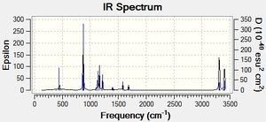
Furthermore, by submitting job type as Frequency in the optimised structure of anti2 conformer of 1,5-hexadiene under both calculation basis HF/3-21G and B3LYP/6-31G*, the electronic energy, sum of electronic and zero-point energies at 0 K and sum of electronic and thermal energies at 298.15 K could be determined as shown in Table 3.
| HF/3-21G a | B3LYP/6-31G* b | |||||||
|---|---|---|---|---|---|---|---|---|
| Electronic energy | Sum of electronic and zero-point energies | Sum of electronic and thermal energies | IR spectrum | Electronic energy | Sum of electronic and zero-point energies | Sum of electronic and thermal energies | IR spectrum | |
| at 0 K | at 298.15 K | at 0 K | at 298.15 K | |||||
| Reactant (anti2) | -231.692534 | -231.539539 | -231.532565 |  |
-234.611703 | -234.469213 | -234.461857 | 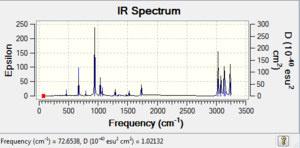 |
Table 3. Summary of energies (in hartree) of the reactant (anti2)
Comparing Figure 8 and 9, both IR spectra are similar which shows that they have similar stretching/bending mode even under different methods of calculations. However, the strongest peak in Figure 8 is at 1112 cm-1 and that in Figure 9 is 940 cm-1. Yet, they correspond to the same mode of vibration, which is the =C-H bending. Therefore, according to the equation, the wavenumber of absorbance, ν can be calculated:
where μ is the reduced mass, k is the spring constant for the bond and c is the light speed,
we can therefore know that the spring constant of the molecule under B3LYP/6-31G* basis reduced.
Now, focusing on gauche3 conformer of the 1,5-hexadiene, similarly, the HF/3-21G optimised molecule was reoptimised by B3LYP/6-31G. The energies and the geometries of the gauche3 1,5-hexadiene under two basis of calculation method were compared and shown in Table 4.

| Calculation Method | Point Group | Energy/ Hartrees | RMS Gradient Norm/Hartrees | Bond length between/ Å | Bond angle between | |||
|---|---|---|---|---|---|---|---|---|
| C14-C12 and C4-C1 | C12-C9 and C6-C4 | C6-C9 | C14-C12-C9 and
C1-C4-C6 |
C12-C9-C6 and
C4-C6-C9 | ||||
| HF/3-21G | C1 | -231.69266120 | 0.00001555 | 1.31646 | 1.50929 | 1.55314 | 125.02428o | 111.80728o |
| B3LYP/6-31G* | C1 | -234.61132605 | 0.00000360 | 1.33382 | 1.50491 | 1.55007 | 125.49464o | 113.46225o |
Table 4. Comparison with the anti2 conformer of 1,5-hexadiene with two calculation method basis (HF/3-21G and B3LYP/6-31G*)
As seen in Table 4, the point group of the same conformer, again, does not change no matter which method of calculation was carried out. The energy of the conformer with B3LYP/6-31G* is lower than that of HF/3-21G. Also, the bond lengths and bond angles changed with a certain amount as shown.
Furthermore, by submitting job type as Frequency in the optimised structure of gauche3 conformer of 1,5-hexadiene under both calculation basis HF/3-21G and B3LYP/6-31G*, the electronic energy, sum of electronic and zero-point energies at 0 K and sum of electronic and thermal energies at 298.15 K could be determined as shown in Table 5.
| HF/3-21G c | B3LYP/6-31G* d | |||||||
|---|---|---|---|---|---|---|---|---|
| Electronic energy | Sum of electronic and zero-point energies | Sum of electronic and thermal energies | IR spectrum | Electronic energy | Sum of electronic and zero-point energies | Sum of electronic and thermal energies | IR spectrum | |
| at 0 K | at 298.15 K | at 0 K | at 298.15 K | |||||
| Reactant (Gauche 3) | -231.692692 | -231.539486 | -231.532646 | 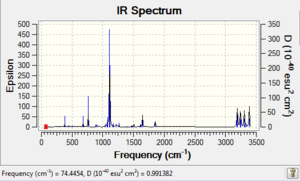 |
-234.611326 | -234.468719 | -234.461477 | 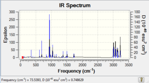 |
Table 5. Summary of energies (in hartree) of the reactant (Gauche3)
Comparing Figure 11 and 12, both IR spectra are similar which shows that they have similar stretching/bending mode even under different methods of calculations. However, the strongest peak in Figure 12 is at 939 cm-1 and that in Figure 11 is 1111 cm-1. Yet, they correspond to the same mode of vibration, which is also the =C-H bending. Therefore, similar to the anti2 conformer's case as mentioned above, we can therefore know that the spring constant of the molecule under B3LYP/6-31G* basis reduced.
Nf710 (talk) 20:36, 17 January 2016 (UTC) Your energies are correct but typically we only do frequency calculations on things that arnt TS to check they are not TSs so we arnt concerned about the frequencies.
Optimisation of transition state
Assuming that the Cope Rearrangement is a concerted reaction, we can therefore say that the reaction will go through the chair and/or boat transition structure. This is important for further calculations and analysis. After optimising the reactants, the chair and boat transition states were optimised accordingly using mainly two different methods. But before that, an allyl fragment (CH2CHCH2) was optimised using HF/3-21G level of theory for the sake of convenience in constructing the chair and boat transition states. A brief summary was shown in Table 6.
| Molecule | Point Group | Energy/Hartree | RMS Gradient Norm/ Hartrees | |||||
|---|---|---|---|---|---|---|---|---|
| Allyl fragment
CH2CHCH2 |
|
 |
C2v | -115.82304010 | 0.00002945 | |||
Table 6. Summary of the optimised allyl fragment
Then, both chair and boat transition state were drawn and optimised using the optimisation to TS (Berny) under HF/3-21G. Figure 14 and Figure C show the optimized structure of the chair transition state while Figure 15 and Figure D show the optimized structure of the boat transition state. Table 7 shows the summary of results.
| Molecule | Point Group | Energy/ Hartree | RMS Gradient Norm/Hartrees | Partial C-C bond length between/ Å | ||||||||||
|---|---|---|---|---|---|---|---|---|---|---|---|---|---|---|
| C14-C6 | C11-C3 | C14-C9 | C6-C1 | C9-C11 | C1-C3 | |||||||||
| Optimised Chair Transition State |
|
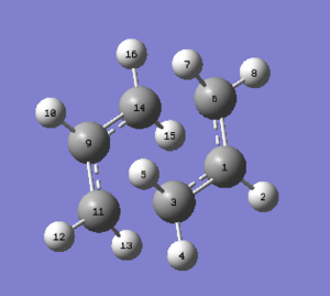 |
C2h | -231.61932238 | 0.00002645 | 2.02016 | 2.02016 | 1.38929 | 1.38930 | 1.38930 | 1.38929 | |||
| Optimised Boat Transition State |
|
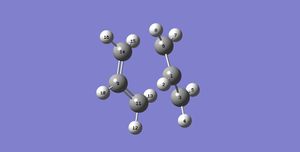 |
C2v | -231.60280235 | 0.00003872 | 2.14060 | 2.14060 | 1.38138 | 1.38138 | 1.38138 | 1.38138 | |||
Table 7. Summary of the optimised chair and boat transition states by optimisation to TS (Berny) under HF/3-21G basis
Furthermore, the transition structures’ Frequencies were calculated as shown in Table 8.
| Molecule | IR spectrum | Imaginary Frequency/ cm-1 | |
|---|---|---|---|
| Boat Transition State | 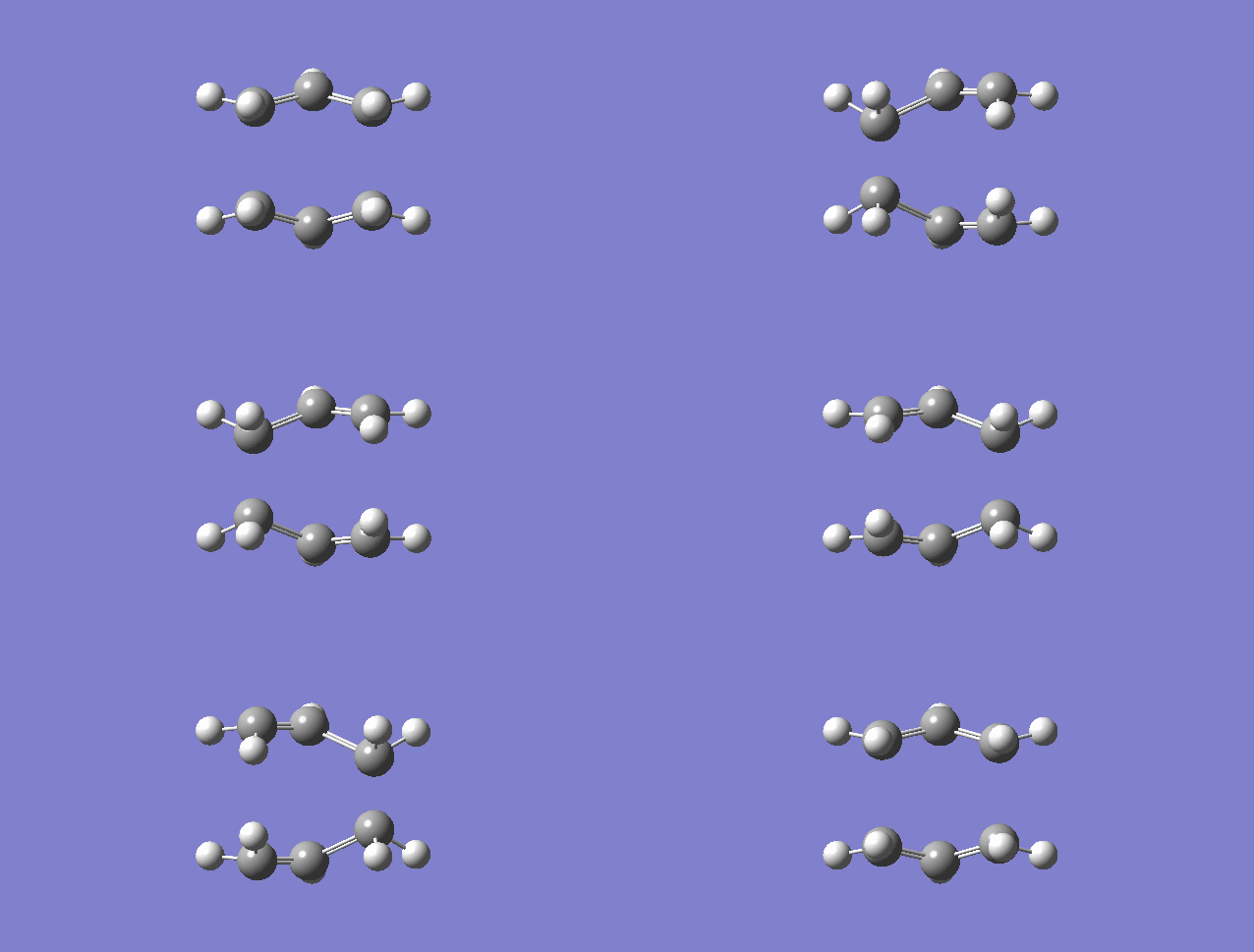
|
 |
-840 |
| Chair Transition State | 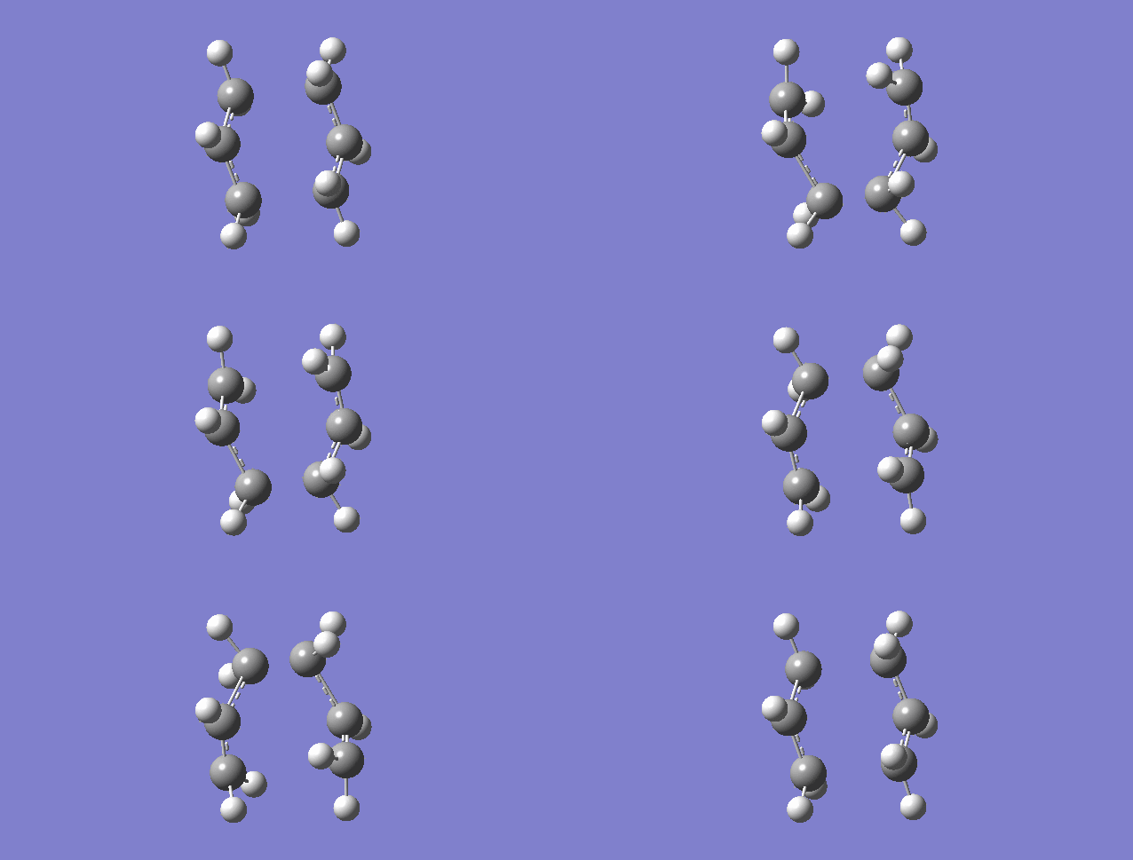
|
 |
-818 |
Table 8. IR spectra and imaginary frequencies of the boat and chair transition states
As you may notice that, the imaginary frequency comes up when calculating with the transition states. This is common, in other words, this should appear to let us know the transition structure we postulated is correct.
A transition state is the first order saddle point on the potential energy surface. Therefore, the force applied to the saddle point against to the displacement. As force and displacement are vectors, the force constant will be a negative number.Therefore, according to
where μ is the reduced mass, k is the spring constant for the bond and c is the light speed,
the square root of a negative force constant k gives an imaginary wave number/frequency v. In other words, the appearance of an imaginary frequency tells us that the structure is a saddle point of the reaction pathway.
The chair transition state was followed by first 'frozen' then 'relaxed'. The boat transition structure was followed by QST2 calculation method.
Chair Transition State
After the above optimisation, the chair transition state was reoptimised again with another method. This method first freezes the coordinate of the molecule, in this case, freeze the bond to be made in the Cope Rearrangement of 1,5-hexadiene as 2.20000 Å. The molecule then optimised with the frozen coordinate. Details of this optimisation was summarized in Table 9.
| Molecule | Point Group |
|
RMS Gradient Norm/ Hartree | Bond length between/ Å | Imaginary Frequency/ cm-1 | IR Spectrum | ||||||||
|---|---|---|---|---|---|---|---|---|---|---|---|---|---|---|
| C6-C14 and C3-11 | C1-C3 and C9-C14 | C1-C6 and C9-C11 | ||||||||||||
| Optimised Chair Transition Structure with frozen coordinate |
|
 |
|
-231.61518510 | 0.00325573 | 2.20000 | 1.38135 | 1.38128 | -765 |  | ||||
Table 9. Summary of the optimisation of the chair transition structure with frozen coordinate(s)
From Table 9, we may notice that the RMS Gradient Norm value is quite far off from zero. Also, the imaginary frequency becomes much higher than -818 cm-1 (Shown in Table 8). With these two pieces of information, we can deduce that the frozen coordinate(s) affect(s) the force constant of the transition state which does not give a good optimisation of transition structure. With that, after applying the frozen coordinate to the molecule, the molecule was reoptimised again with a degree of Derivative to the Bond. Details of the reoptimisation were presented in Table 10.
| Molecule | Point Group | Energy/ Hartree | RMS Gradient Norm/ Hartree | Bond length between/ Å | Imaginary Frequency/ cm-1 |
| ||||||||
|---|---|---|---|---|---|---|---|---|---|---|---|---|---|---|
| C14-C6 | C11-C3 | C14-C9 and C6-C1 | C9-C11 and C1-C3 | |||||||||||
| Optimised Chair Transition
Structure with a degree of Derivative to the Bond |
|
 |
C2h | -231.61932233 | 0.00002127 | 2.02075 | 2.02071 | 1.38929 | 1.38930 | -818 |  | |||
Table 10. Summary of the reoptimisation of the chair transition structure with a degree of Derivative to the Bond
Now, in Table 10, the RMS Gradient Norm value is close to zero. Also, the imaginary frequency goes back to -818 cm-1, indicating that the coordinates no longer be frozen and the stretching/bending mode of the transition state is able to undergo freely.
Comparing the bond lengths in Table 7 and 10, we can see that the difference between bond lengths of the single bond to be made/ broken calculated in two methods is just less than 0.0006 Å. And also, there is no difference in bond length of the double bond to be make/broken ‘inside’ the system. This tells us that the two optimisation methods are rather similar under the consideration on the Cope Rearrangement Reaction.
Boat Transition State
Instead of using the frozen coordinate method as for the chair transition state above, another method, QST2, was applied to the boat transition state under the HF/3-21G basis. In order to use this method, without any ‘Link died’, the reactant and product have to be drawn and labelled carefully. QST2 is a method which interpolates the reactant and product to give a transition state. Therefore, it will fall if the structure of the reactant and product are not close to the transition state. And therefore, all molecules have to be carefully labelled and adjusted.

Figure 22. The drawings and adjustments of angles of the reactant (left) and product (right) for QST2 Method, i.e. the central C-C-C-C dihedral angle was changed to 0o and inside C-C-C were reduced to 100o
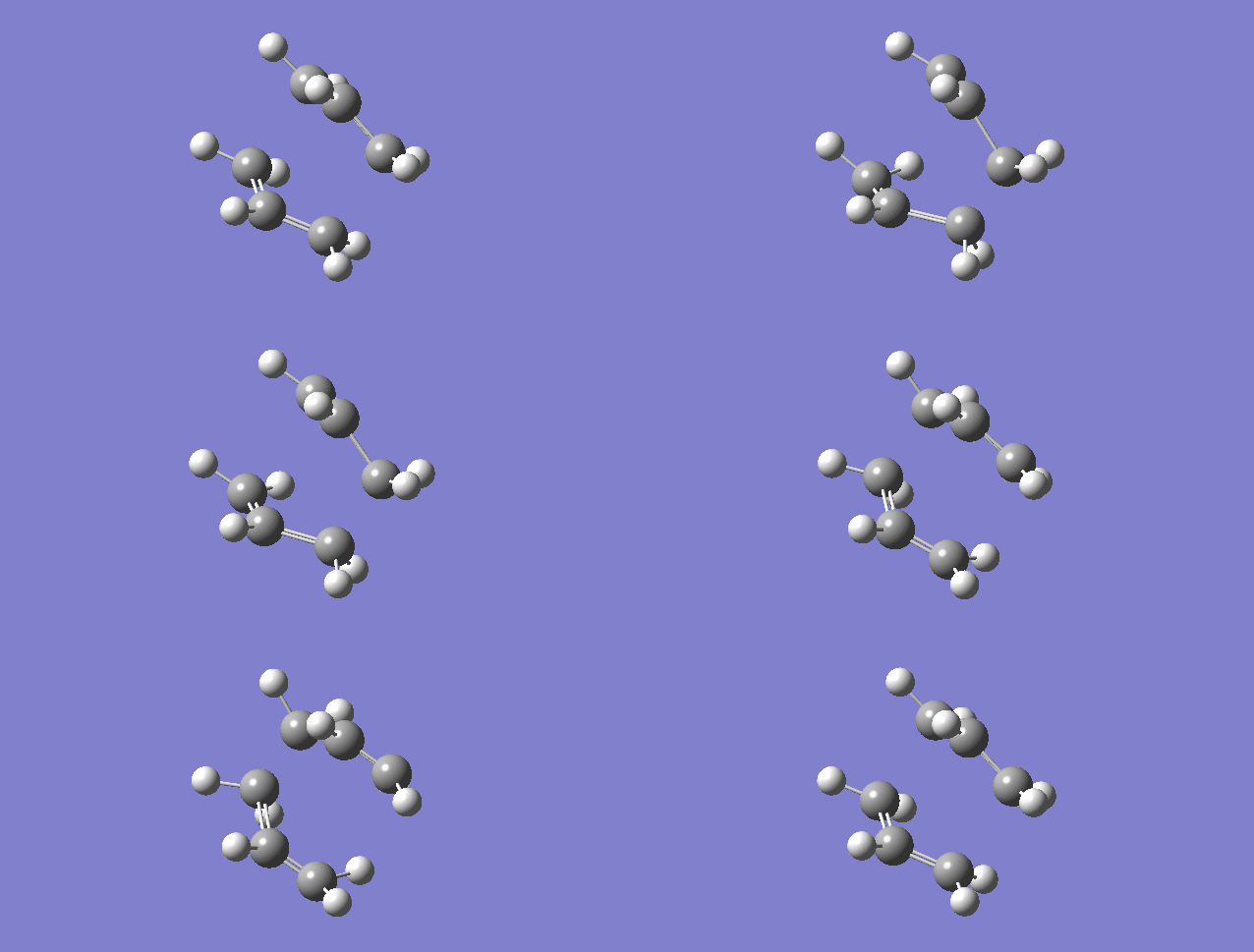
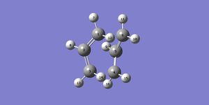
After the adjustment, the job was run and the optimized molecule converge to the boat transition structure. Summary was shown in Table 11.
| Molecule | Point Group | Energy/Hartree | RMS Gradient Norm/ Hartree | Bond length between/ Å | Imaginary Frequency/ cm-1 | IR spectrum | ||||
|---|---|---|---|---|---|---|---|---|---|---|
| C1-C6 | C3-C4 | C5-C6, C4-C5, C3-C2 and C1-C2 | ||||||||
| Boat transition structure
under QST2 method |
|
 |
C2v | -231.60280241 | 0.00002436 | 2.13994 | 2.14019 | 1.38149 | -840 | 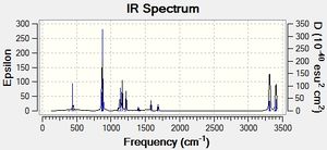 |
Table 11. Summary of the boat transition structure under QST2 method
Intrinsic Reaction Coordinate (IRC)
In order to confirm that our transition state is of the correct one, Intrinsic Reaction Coordinate (IRC) will be carried out.
As mentioned above, transition state is the first order saddle point of the reaction pathway. Therefore, it will start to go to the product or back to the reactant with it falls off. It resembles that a ball is at the tip of the mountain, which starts to roll off the mountain on the side with the steepest slope. Also, when we are doing IRC, we can determine whether the reaction goes forward, backward or both sides. Also, the number of points, which means the number of little steps that the geometry of the molecule changes, can be adjusted. A low number of points will just give us a very rough idea that tell us a little bit about our transition state. Also, the last point on the IRC is far from the minimum geometry. A high number of points gives us more accurate results, however two problems could be raised. First, the time for calculation will be long and Most importantly, as it goes down the slope and reaches the minimum geometry, i.e. the plateau of energy, the slope will become very small or even zero again. However, as the energy difference of the next or previous geometry compared to the geometry of itself is too small, GaussView 5.0 may not able to know which direction the molecule should proceed to. And this, therefore, results in ‘Link died’. Therefore, the most common technique is to have a good number of points, then take the last point on the IRC and run it with a normal optimisation.
Here, as we know that the Cope Rearrangement has a symmetric reaction pathway, taking the chair transition structure, we will run IRC on it with 50 points.
 |
 |
|
|---|
Figure 27. The product of the Cope Rearrangement after optimisation
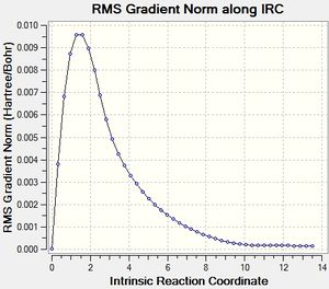
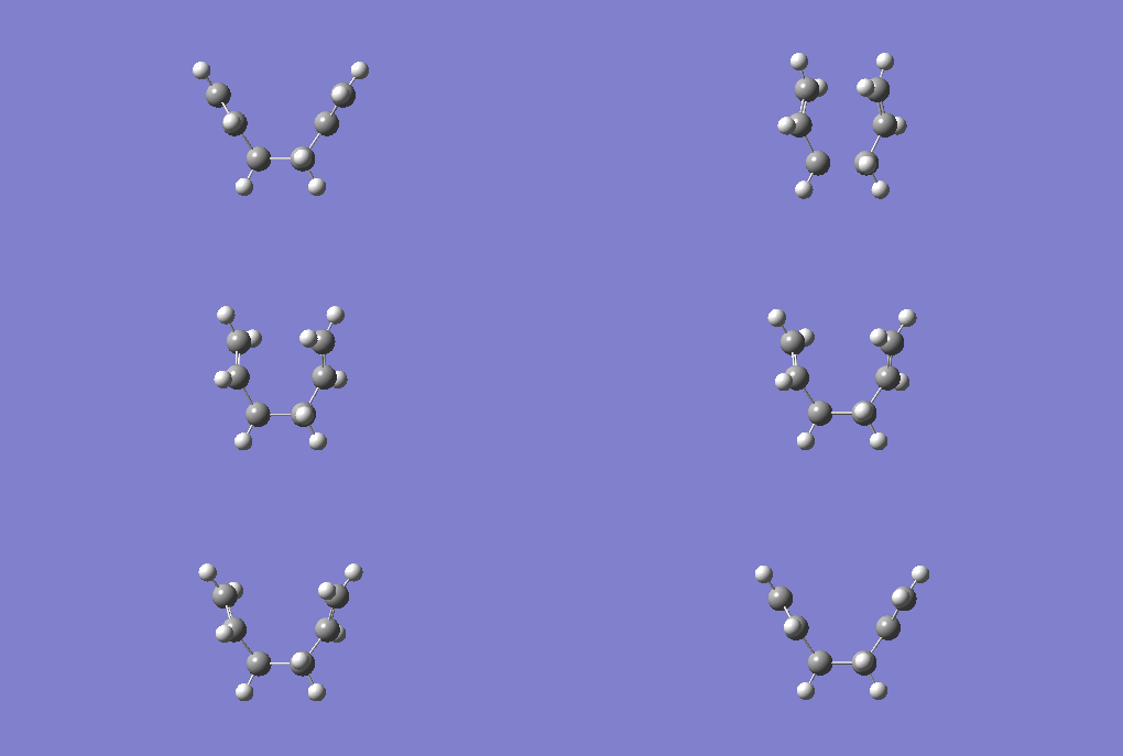
The first point on Figure 25 is -231.61932233 Hartree and the last point is -231.69157881 Hartree. Then, we take the last point and optimise it, we get the structure shown in Figure 27.
The structure is of C2 symmetry and the energy calculated is -231.69166702 Hartree. This matches with Gauche2 C2 on Appendix 1. And therefore, this is how the conformer of 1,5-hexadiene connects with the chair transition structure.
====== Activation Energy of the Cope Rearrangement ======
Finally, we optimise the chair and boat transition states we got from above, reoptimise it with job Opt + Freq under a more advanced calculation B3LYP/6-31G*. And from that, the thermochemistry data were given and we can know the activation energy of the reaction by comparing to Table 3, which anti2 is used as a local minimum rather than gauche3 as a global minimum.
| HF/3-21G | B3LYP/6-31G* | |||||
|---|---|---|---|---|---|---|
| Electronic energy | Sum of electronic and zero-point energies | Sum of electronic and thermal energies | Electronic energy | Sum of electronic and zero-point energies | Sum of electronic and thermal energies | |
| at 0 K | at 298.15 K | at 0 K | at 298.15 K | |||
| Chair TSText[1][2] | -231.619323 | -231.466698 | -231.461339 | -234.556983 | -234.414929 | -234.409009 |
| Boat TS[3][4] | -231.602803 | -231.450932 | -231.445303 | -234.543094 | -234.402342 | -234.396008 |
| Reactant (anti2) | -231.692534 | -231.539539 | -231.532565 | -234.611703 | -234.469213 | -234.461857 |
Table 11. Summary of energies of chair, boat and reactant (anti2) structure
| HF/3-21G | HF/3-21G | B3LYP/6-31G* | B3LYP/6-31G* | Expt. | |
| at 0 K | at 298.15 K | at 0 K | at 298.15 K | at 0 K | |
| ΔE (Chair) | 45.71 | 44.69 | 34.06 | 33.16 | 33.5 ± 0.5 |
| ΔE (Boat) | 55.60 | 54.76 | 41.96 | 41.32 | 44.7 ± 2.0 |
Table 12. Summary of activation energies in kcal/mol
Nf710 (talk) 21:27, 17 January 2016 (UTC) In general you have done a very thorough report here. perhaps in future try to keep the report more concise. You have shown a good understanding the theory and shown some understanding of the computational models. You could have included dihedrals in your geometry comparisons. Well done for identifying the correct conformer which the IRC connects.
The Diels-Alder Cycloadditions
Ethylene and Cis-Butadiene
First, the structures of the reactants, ethylene and cis-butadiene, were optimised to minimum under semiempirical AM1 method. For the butadiene, in order to be in the cis conformer, the dihedral angle was adjusted to be 0o. Details are listed in Table 13.
| Molecule | Point Group | HOMO | LUMO | Energy/Hartree | RMS Gradient Norm/ Hartree | IR spectrum | ||||
|---|---|---|---|---|---|---|---|---|---|---|
| Ethylene |
|
D2h |  |
 |
0.02619029 | 0.00008755 |  | |||
| Cis-Butadiene |
|
C2v | 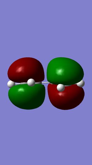 |
 |
0.04878534 | 0.00000087 |  |
Table 13. Summary of optimised ethylene and cis-butadiene
(You are displaying incorrect models with Jmol. You need to include script to fix this. Additionally, a few words of code will allow you to use Jmol to display vibrations Tam10 (talk) 10:19, 7 January 2016 (UTC))
Looking into Figure 30-33, as we know that the plane is perpendicular to the molecule, the HOMO of Ethylene is symmetric while that of LUMO is antisymmetric.
Also, the HOMO of cis-butadiene is antisymmetric and that of LUMO is symmetric.
Then, the transition state of the reaction was able to constructed using the optimised structure of the reactants made above. By making the bond lengths of the bonds to be made in Diels-Alder [4+2] cycloaddition to 2.20000 Å in the transition state, which is the 'dash bond', the transition structure was optimized to Opt + Freq minimisation to TS (Berny) under the same method of calculation - semiempitical AM1. Details are listed in Table 14.
| Molecule | Point Group | HOMO | LUMO | Energy/Hartree | RMS Gradient Norm/ Hartree | Imaginary Frequency/ cm-1 | IR spectrum | |||||
|---|---|---|---|---|---|---|---|---|---|---|---|---|
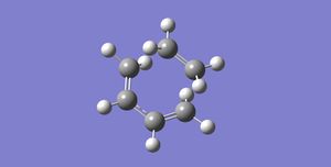
| Transition state |
|
 |
C1 |  |
 |
0.11165467 | 0.00002792 | -956 |  | |||
Table 14. Summary of optimised transition state
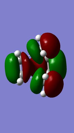
From Figure 36, we can see that the HOMO of the transition state is antisymmetric whilst the LUMO of the transition state is symmetric. By making very careful comparison between Figure 36, Figure 37 and Figure 30-33, we can see that the HOMO of the transition state in Figure 36 is a combination of Figure 32 and 30; the LUMO of the transition state in Figure 37 is a combination of Figure 31 and 33. We can clearly see that the HOMO and LUMO of the transition state have a complementary combination of HOMO and LUMO of the reactants.
Taking a closer look to HOMO of the transition state. Recalling Woodward Hoffmann’s Rule, (4q+2)s+(4r)a = odd for thermally allowed reaction, we have both π2s and π4s. Therefore, the reaction is thermally allowed by letting q = 0, which gives the value of 1 which is odd.
Furthermore, from Table 14, we notice that there is an imaginary frequency reported at -956 cm-1. As explained above, the transition state should have one imaginary frequency to account for the negative force constant. With that, this imaginary frequency confirms that the transition structure we postulated from the optimised reactants is valid, i.e. it is really a transition state. The animation of where the imaginary frequency originates from, which shows the motion of the transition state - how the two reactants approach to each other and bonds are formed, is shown below.
From the above figure, we can see that the bond formation from the reactant to the product happens at the same time, i.e. synchronous, on both sides of the transition structure. Therefore, we can say that this Diels-Alder cycloaddition is a concerted [4+2] pericyclic cycloaddition, which matches with what we learnt in Pericyclic Reaction course.
On top of that, the geometry of the transition structure was investigated by looking into the optimised bond lengths between carbon atoms Details are shown in Figure 38 and Table 15.

| Bond length/ Å | |
|---|---|
| C7-C9 | 2.11938 |
| C12-C5 | 2.11944 |
| C12-C9 | 1.38284 |
| C3-C7 | 1.38187 |
| C3-C1 | 1.39750 |
| C5-C1 | 1.38175 |
Table 15. Geometry analysis of the transition state
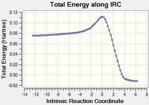
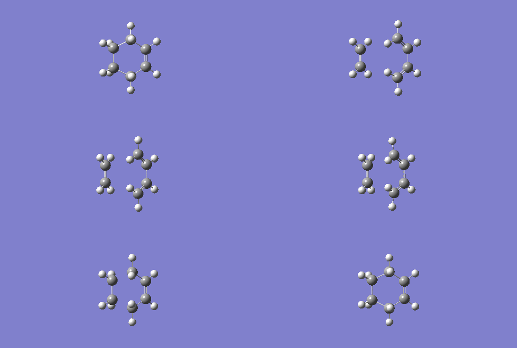
According to the literature [11], C-C carbon-carbon single bond is 1.54 Å, and C=C carbon-carbon double bond is 1.34 Å. Also, the Van der Waals radius of carbon is 1.70 Å,[12] According to the reaction scheme shown in Figure 3, a single bond is forming between C7 and C9, also another single bond is forming between C12-C5. Comparing the data in Table 15 with the literature, we can see that the bond length of two bonds to be made is longer than C-C, but shorter than the twice of carbon's Van der Waals radius. This tells us some hints that the terminal carbons between two reactants are attracting with each other to a certain degree. Furthermore, taking a look to other carbon-carbon bonds within the system, we notice that they are somewhere between C-C and C=C. This tells us that either C-C is becoming C=C or C=C is becoming C-C in the transition state. After that, the IRC of the above optimised transition state was carried out with both direction and force constant calculated always for 50 points to see the reaction profile.
 |
 |
|
In Figure 39, we can clearly see that the reactants was first passed through the energy barrier to get the transition state and it went down the slope to give the product. The last geometry point of the IRC was taken to run a normal optimisation as shown in Figure K. The energy has become -0.01619492 Hartrees and RMS Gradient Norm is 0.00000954 Hartrees, which is very close zero. In other words, the geometry now is now really optimized to minimum.
Figure K: Optimised last point of IRC of Cis-butadiene and Ethylene |
Finally, the activation energy for this reaction was calculated in Table 16.
| Ethylene | Cis-butadiene | Transition state | Activation Energy | |
|---|---|---|---|---|
| Energy/Hartree | 0.02619029 | 0.04878534 | 0.11165467 | 0.03667904
(23.02 kcal/mol) |
Table 16. Activation energy analysis of Diels-Alder Reaction between ethylene and cis-butadiene
Cyclohexa-1,3-diene and Maleic Anhydride
First, the structures of the reactants, ethylene and cis-butadiene, were optimised to minimum under semiempirical AM1 method. Details are listed in Table 17.
| Optimised Structure | Molecule | Point Group | Energy/Hartree |
|---|---|---|---|
| Cyclohexa-1,3-diene | 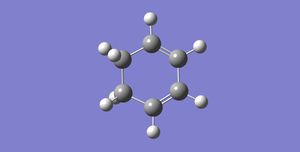 |
C2 | 0.02771130 |
| Maleic Anhydride |  |
Cs | -0.12182418 |
Table 17. Summary of the optimized reactant
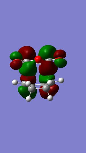
Then, the two transition states, exo and endo, of the reaction were able to construct. By making the bond lengths of the bonds to be made in Diels-Alder [4+2] cycloaddition to 2.20000 Å in the transition state, which is the 'dash bond', the transition structure was optimized to Opt + Freq minimisation to TS (Berny) under the same method of calculation - semiempitical AM1. Details are listed in Table 18.
| Transition Structure | Molecule | Point Group | HOMO | LUMO | Energy/Hartree | RMS Gradient Norm/ Hartree | Imaginary Frequency/ cm-1 | IR spectrum |
|---|---|---|---|---|---|---|---|---|
| Exo |  |
C1 | 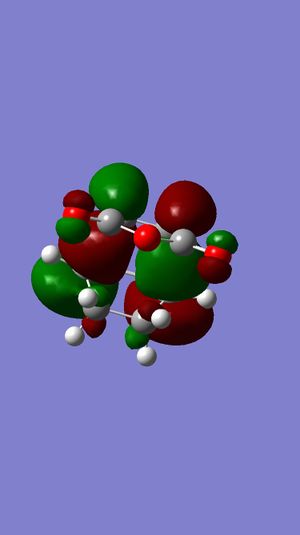 |
 |
-0.05041984 | 0.00000883 | -812 | 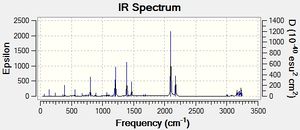 |
| Endo | 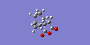 |
C1 |  |
 |
-0.05150469 | 0.00004308 | -807 | 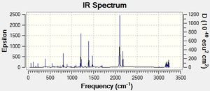 |
Table 18. Summary of the optimized transition structures
In Table 18, we can see that both HOMO and LUMO of the exo transition state are antisymmetric with respect to the plane. Also, both HOMO and LUMO of the endo transition state are antisymmetric as well.
Also, we notice that the energy of exo is higher than that of endo. This can be explained by the poorer overlap between the C=C π and C=O π* compared to that of endo. This is called secondary orbital effect, which will be further discussed below.
There is one imaginary frequency in both transition structure. This confirms that both of them are valid postulated transition structures.
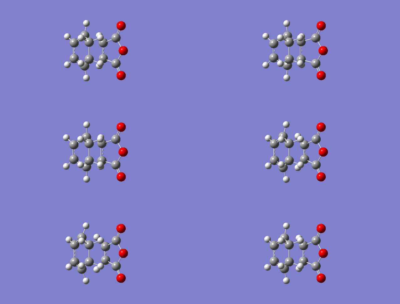
Imaginary frequency of exo transition state animation |
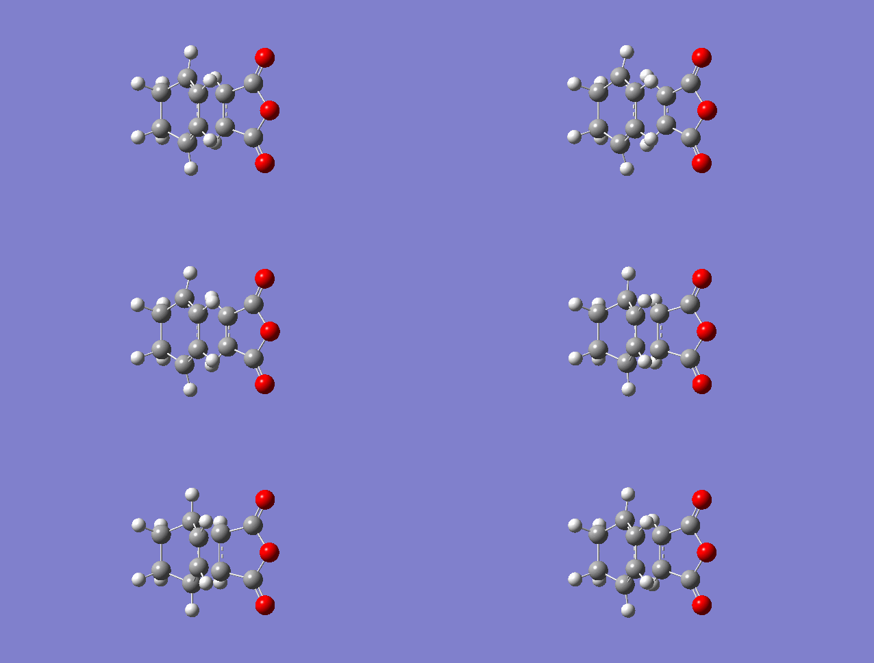
Imaginary frequency of endo transition state animation |
Again, from the above animations, we can see that the bonds are formed in a synchronous fashion, which means the Diels-Alder Cycloaddition reaction is concerted.
Furthermore, the geometries of both transition states were examined carefully in Table 19.
| Geometry summary of Exo Transition State (Please refer to Figure 43 for atom labelling) | Geometry summary of Endo Transition State (Please refer to Figure 44 for atom labelling) | ||||||||||||||||||||||||||||||||||||||||||||||||||||||||||||||||||||
|---|---|---|---|---|---|---|---|---|---|---|---|---|---|---|---|---|---|---|---|---|---|---|---|---|---|---|---|---|---|---|---|---|---|---|---|---|---|---|---|---|---|---|---|---|---|---|---|---|---|---|---|---|---|---|---|---|---|---|---|---|---|---|---|---|---|---|---|---|---|
|
| ||||||||||||||||||||||||||||||||||||||||||||||||||||||||||||||||||||
Table 19. Geometry analysis of exo and endo transition states
(This section below needs a look over - some spelling and grammar issues making it difficult to read Tam10 (talk) 10:14, 7 January 2016 (UTC))
According to the reaction scheme shown in Figure 4, a single bond is forming between C5 and C13, also another single bond is forming between C6-C14 for exo; C15 and C7 plus C16 and C5 for endo, which is what the first row in the two tables in the left and right in Table 19 shows. the single bond to be made Comparing these values with literature, we find that they are longer than C-C but shorter than twice of carbon's Van der Waals' radius. This tells us some hints that these pairs of carbons between two reactants are attracting with each other to a certain degree. Furthermore, taking a look to other carbon-carbon bonds within the system, i.e. except row 1 and those labelled with (through space), we notice that they are somewhere between C-C and C=C. This tells us that either C-C is becoming C=C or C=C is becoming C-C in the transition state.
Now, looking at the through space bond length. In the exo transition structure, the through space distance -(C=O)-O-(C=O)- fragment of the maleic anhydride and the C atoms of the “opposite” -CH2-CH2- is smaller than the twice of the Van der Waals radius but larger than C-C which gives us a hint that they might interact. In the endo transition structure, the through space distance -(C=O)-O-(C=O)- fragment of the maleic anhydride and the C atoms of the “opposite” -CH=CH- is smaller than the twice of the Van der Waals radius but larger than C-C which gives us a hint that they might interact. However, according to the definition of secondary orbital effect, it is looking for the interaction between the C=C π of the diene and C=O π* of the dienophile. Endo clearly shows that as explained, but exo seems to just demonstrate the sterics clash between the -(C=O)-O-(C=O)- fragment of the maleic anhydride and the C atoms of the “opposite” -CH2-CH2- fragment of diene. In order to further confirm that exo has no secondary orbital effect, a measurement of bond length was carried out between -(C=O)-O-(C=O)- fragment of the maleic anhydride and the -CH=CH- in diene in the exo transition state. The result was shown in the last row on the left table in Table 19. This shows that they are too far away which means they are not possible to interact.
(Avoid repeating yourself. "is smaller than the twice of the Van der Waals radius but larger than C-C which gives us a hint that they might interact" is used twice Tam10 (talk) 10:14, 7 January 2016 (UTC))
Now, looking back to the HOMO of exo and endo transition states in Figure 45 and 46 respectively. We can definitely see that the overlap between the two reactants is relatively smaller in exo. From these two pieces of information, we can conclude that the endo is kinetically controlled, while exo is thermodynamically controlled.
(Did you calculate the reaction energies to confirm that exo is thermodynamically controlled? Tam10 (talk) 10:14, 7 January 2016 (UTC))
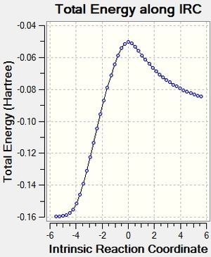
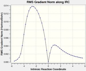
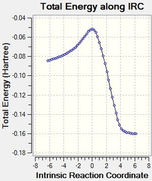
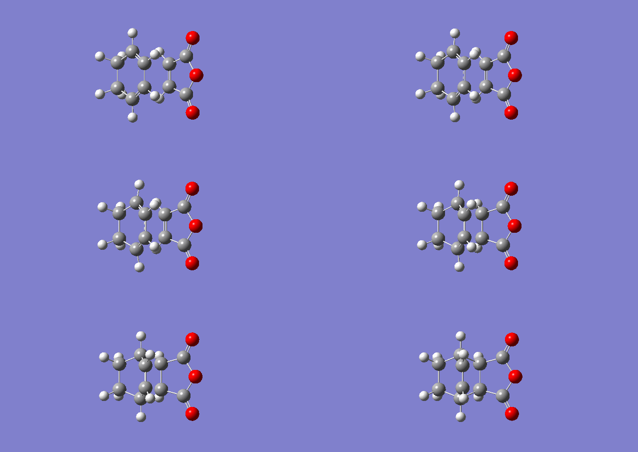
After that, the IRC of the both optimised transition state was carried out with both direction and force constant calculated always for the reaction profile. 21 points were used for exo transition states and 24 for endo (reasons explained under Introduction) to see the reaction profiles.
| Exo Transition State | Endo Transition State | ||||
|---|---|---|---|---|---|
 |
 |
|
 |
 |
|
And eventually, the activation energies of the reaction via different transition structures were summarised in Table 20.
| Cyclohexa-1,3-diene | Maleic Anhydride | Endo Transition State | ExoTransition State | Activation Energy via endo | Activation Energy via exo | |
|---|---|---|---|---|---|---|
| Energy/Hartree | 0.02771130 | -0.12182418 | -0.05150469 | -0.05041984 | 0.04260819
(26.74 kcal/mol) |
0.04369304
(27.42 kcal/mol) |
Table 20. Activation energy analysis
Conclusion
Three reactions, namely the Cope Rearrangement of 1,5-hexadiene, the Diels-Alder cycloadditions of ethylene and cis-butadiene and cyclohexa-1,3-diene and maleic anhydride, were investigated by different computational methods by GaussView 5.0. For the Cope Rearrangement, mainly two modes of calculation methods were applied, i.e. HF/3-21G and B3LYP/6-31G*. The later one gives a more accurate result close to the experimental value. Also, from the computation, the chair conformation was found to be lower in energy than boat conformer and the activation energy of the reaction was calculated. For the Diels-Alder cycloadditions, only one method, semiempirical AM1, was employed. This is a simpler technique as it ignore the core overlap integral (NDDO). HOMO and LUMO were visualised and the secondary orbital effect was viewed clearly. With that, endo transition state pathway is more favourable although the endo product is less stable than the exo product. Apart from NDDO in AM1, there are quite a few limitations in this computational experiment. When we are adjusting the bond to be formed while constructing transition state, we usually make that bond be 2.20000 Å. Sometimes it is hard to do so, therefore, the molecule has to be loosen. This may also need to some effects to our computational experimental data. Further efforts can be devoted on using a more substitutred 1,5-diene in the Cope Rearrangement, or even investigating on the Claisen Rearrangement. The idea of the Cope Rearrangement originally stemmed from the Claisen Rearrangement. Also, Claisen Rearrangement involves ‘O’ as an heteroatom. This might be interesting. Also, for the Diels-Alder cycloadditions, more different kinds of dienophiles can be applied and the energies and reaction pathway of the cycloaddition reactions can be compared.
Reference
- ↑ C. D. Sherrill, An Introduction to Hartree-Fock Molecular Orbital Theory, 2000
- ↑ What is B3LYP?, https://www.quora.com/What-is-B3LYP (accessed December 2015)
- ↑ C. H. Patterson, International Journal of Quantum Chemistry, 2006, 106 (15), 3383
- ↑ A. D. Becke, The Journal of Chemical Physics, 1993, 98, 5648
- ↑ M. J. S. Dewar, E. G. Zoebisch, E. F. Healy and J. J. P. Stewart, J. Am. Chem. Soc., 1985, 107 (13), 3902
- ↑ A. C. Cope and E. M. Hardy, J. Am. Chem. Soc., 1940, 62 (2), 441
- ↑ O. Wiest, K. A. Black and K. N. Houk, J. Am. Chem. Soc., 1994, 116, 10336
- ↑ N. H. Kendall, Y. Li and J. D. Evanseck, Angew. Chem. Int. Ed. Engl., 1992, 31 (6), 682
- ↑ B. G. Rocque, J. M. Gonzales and H. F. Schaefer, Molecular Physics, 2002, 100 (4), 441
- ↑ M. Nishio and M. Hirota, Tetrahedron, 1989, 45 (23), 7201
- ↑ M. A. Fox and J. K. Whitesell, Organische Chemie: Grundlagen, Mechanismen, Bioorganische Anwendungen, Springer, 1995
- ↑ A. Bondi,(1964), J. Phys. Chem., 1964, 68 (3), 441


