Rep:Mod:fs1309module 3
3rd year computational lab Module 3 Transition states and reactivity.
Abstract:
This module aims to characterize transition structures on potential energy surfaces for the Cope rearrangement and Diels Alder cycloaddition reactions. This can be achieved by applying molecular orbital-based methods, solving the Schrodinger equation numerically, and locating transition structures based on the local shape of a potential energy surface. Together with showing what transition structures look like, reaction paths and barrier heights can also be calculated.
Part 1:
The Cope Rearrangement Tutorial

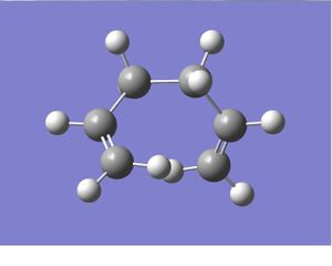
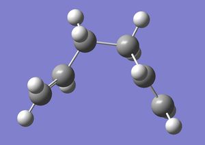
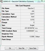
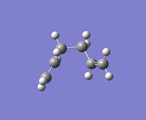
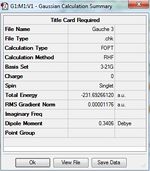
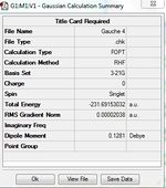
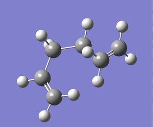
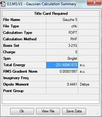
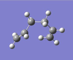
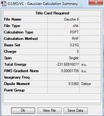
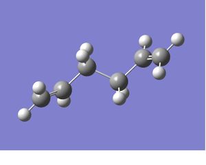
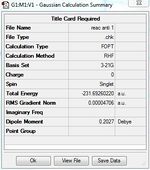
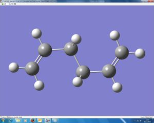
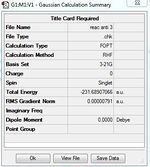
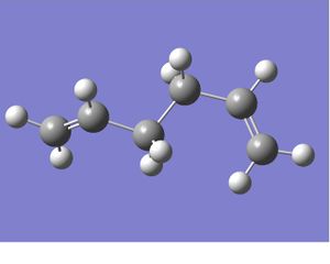
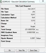
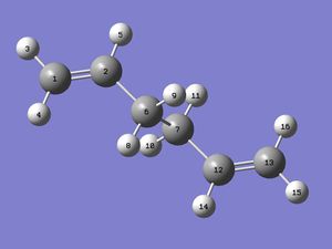
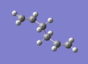
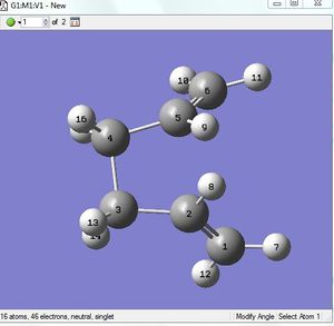
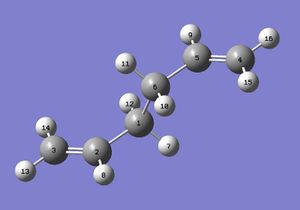
1)Optimizing the Reactants at HF/3-21G level theory. The energy of different conformers can be found in the summary table after optimization, and the symmetry is determined using Symmetrize under Edit menu. The table below shows the structures of optimized conformers and their energies.
Reoptimization and frequency analysis of Anti 2 conformer at B3LYP/6-31G* level after optimization at HF/6-31G level of theory.
Section 1 Optimization
Change in structure:

The two structure are very similar, the small differences is found after comparing their total energies and geometric parameters such as bond angle, dihedral angle and bone length data obtained for the identical molecule but with different level of theory. It is noted that: 1)The total energy predicted at HF/6-31G level is much lower than what was obtained at B3LYP/6-31G* level, the relative energy is 2) The bond lengths obtained at HF/3-21G level are in general slightly shorter than those obtained at B3LYP/6-31G* level; 3) The most significant differences are found in the dihedral angle between central atoms and alkene carbon atoms, e.g: H(9)-C(6)-C(2)-C(1) C(7)-C(6)-C(2)-C(1). The maximum difference in dihedral angle is around 4°.
Section 2 Frequency analysis
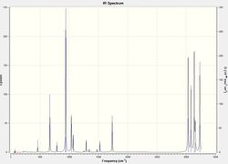
No imaginary frequencies are found after checking the vibration results and spectrum, this means the optimized structure is not a transition structure. The thermochemistry data below are obtained from the output file.
Sum of electronic and zero-point Energies(E=Eelec+ZPE)= -234.469231
Sum of electronic and thermal Energies(E=E+Evib+Erot+Etrans)=-234.461865
Sum of electronic and thermal Enthalpies(E=E+RT)=-234.460920
Sum of electronic and thermal Free Energies(G=H-TS)=-234.500877
2) Optimizing the "Chair" and "Boat" Transition Structures
Section 1. Single allyl fragment optimization using the HF/3-21G level of theory.
| Structure of allyl fragement | Summary table | Comparison to transition structure |
|---|---|---|
 |
 |
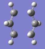 |
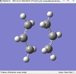
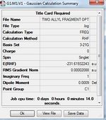
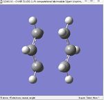
The structure of single allyl fragment look like one half of the transition structures shown.
Section 2. Chair two allyl fragments optimization
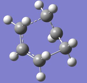
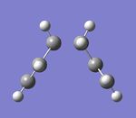
This animation of imaginary frequency at -817.87cm-1 (as shown on the right) corresponds to the Cope rearrangement as it shows both bond forming and breaking at different ends of two allyl fragments in the transition structure .
Section 3 Optimization of the boat transition structure using QST2 method
The reactant and product were firstly numbered using atom list under edit menu, the first QST2 trial failed. After modification by changing the central C-C-C-C (C2-C3-C4-C5) dihedral angle to 0o, followed by reduce the inside angle (C2-C3-C4 and C3-C4-C5) to 100o, a more reasonable boat transition structure was obtained.
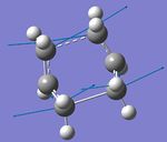
The imaginary frequency was found at -840.01 cm-1. The corresponding motion is shown on the right.
f) Optimization of chair transition structure using IRC method
IRC method is used here to predict which conformer the reaction paths from the transitions structures will lead to.
Method 1: take the last point on the IRC and run a normal minimization; Method 2: restart the IRC and specify a larger number of points until it reaches a minimum; Method 3: redo the IRC specifying that you want to compute the force constants at every step. There are advantages and disadvantages to each of these approaches.
Similar conformers are obtained from method 1 and 3, which indicates the transition structures connect to the Gauche 2 conformer.
Activation energy analysis.
| Transition structure | HF/3-21G at 0K /(kcal/mol) | HF/3-21G at 298.15K/(kcal/mol) | B3LYP/6-31G* at 0K/(kcal/mol) | B3LYP/6-31G* at 298.15K/(kcal/mol) | Expt. /(kcal/mol) |
|---|---|---|---|---|---|
| Chair | 45.71 (45.70) | 44.69(44.69) | 34.09(34.06) | 33.23(33.17) | 33.5±0.5 |
| Boat | 55.60 (55.60) | 55.12(54.76) | 41.98(41.96) | (41.32) | 44.7±2.0 |
The numbers in bracket are literature values in appendix 2.
Comment on the results: The electronic energy and the sum of electronic and zero point energies both match the literature values very well, but the actual calculated values of the sum of electronic and thermal energies show a small difference with data given in appendix 2. This could only due to errors introduced during the calculation, as overall activation energies still match the literature value very well.
Part 2 Exercise AM1 semi empirical orbital method is used here for initial calculation, followed by calculation at HF/3-21G theory level for further transition structure optimization.
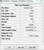
Section 1 Optimization of cis butadiene and determination of the symmetry of corresponding HOMO and LUMO
Section 2 Computation of the Transition State geometry for the prototype reaction and an examination of the nature of the reaction path.
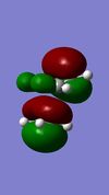
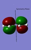
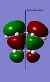
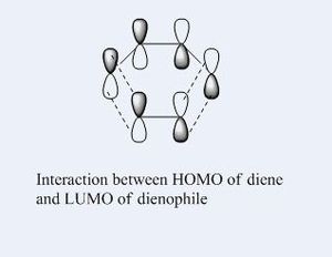
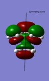
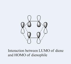
The Diels Alder reaction here, which involves two new α bonds forming due to the interaction between the diene's HOMO/LUMO and dienophile's LUMO/HOMO interaction, is a class of pericyclic reactions. Such reaction can only proceed if the π/π* orbitals involved have correct symmetry. According to the selection rules in pericyclic reaction, such 6 electrons system can interact if the stereochemistry of two interacting orbitals are supra facial or two anti-facial. The HOMO and LUMO obtained from the transition structures both are consistent with the stereochemistry in the selection rules, as the HOMO show suprafacial interaction between diene and dienophile's interacting orbitals (HOMO of diene and LUMO of dieneophile), and LUMO show suprafacial interaction between diene and dienophile's interacting orbitals (LUMO of diene and HOMO of dieneophile).
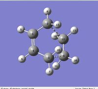
| Level of theory | Bonding between (n)C and (n')C | Bond length/Å | Bonding between (n)C and (n')C | Bond length/Å | Bonding between (n)C and (n')C | Bond length/Å | Bonding between (n)C and (n')C | Bond length/Å |
|---|---|---|---|---|---|---|---|---|
| Semi-empirical AM1 | (2)C --(12)C and (3)C --(9)C | 2.12 | (2)C --(1)C and (3)C --(4)C | 1.38 | (1)C and (4)C | 1.40 | (1)C and (4)C | 1.38 |
| HF/3-21G | (2)C --(12)C and (3)C --(9)C | 2.21 | (2)C --(1)C and (3)C --(4)C | 1.37 | (1)C and (4)C | 1.39 | (1)C and (4)C | 1.38 |
n and n' here are used to indicate the bonding carbon atoms. The 6 electrons system can interact when stereochemistry of two interacting orbitals are supra facial or two anti-facial.
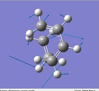
Similar structures were obtained for AM1 and HF/3-21G method, the only difference is the distance between diene and dienophile. According to the literature, the typical bond lengths of sp3 and sp2 C-C bond are 1.54Å and 1.34Å respectively, the van der waal's radius of carbon is 1.70Å. The newly form α bonds origin from 1) breaking of C-C double, 2) two partly formed α bonds between diene and dienophile. The first cases can be proven as the double bonds in dienophile and diene are longer than the typical carbon carbon double bond length, but shorter than the typical C-C α bond;

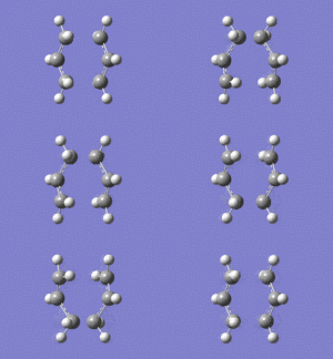
and the α bond length in the cie-butadiene has shortened significantly. As the diene and dienophile are two separate components before the Diels Alder reaction, a typical carbon van der waal's radius can be used here to approximate the distance between these carbons before the reaction, which is around 3.40Å (=2*1.70Å). While in the transition structure, this distance has been shortened significantly to 2.12Å. This can be further proven by looking at the animation of imaginary frequency at -955.87cm-1, the ends of dienophile and diene are getting closer to each other. This also proves the fact that two new α bonds are partly forming in the transition structure. The diene and dienophile do not approach to each other to form α bonds between them in the animation of the lowest positive frequency(as shown in the left).
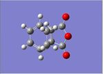
Section 3 Diels Alder reaction between cyclohexa-1,3-diene reaction with maleic anhydride:
This reaction can proceed as the π/π* orbitals involved have correct symmetry.
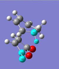
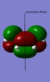
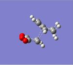
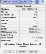
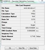
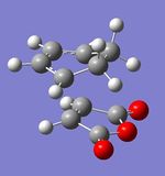
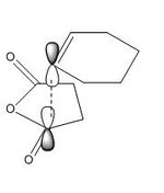
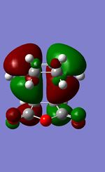
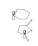
The endo transition structure is lower in energy than the exo structure by 0.71kcal/mol if calculation is done with semi-empirical AM1 method, but opposite results were obtained for HF/3-21G method. The structural different between the endo and exo is due to the different orientations of maleic anhydride. A possible reason for exo form is more strained is due to the electronic repulsion between electrons in C-H α orbital (atom 1 and 2) and C=O π orbital (atom 3 and 4) in the exo form (as shown on the right). This results in an increase in energy of the transition structure. Such interaction does not happen in the endo form as the C-H α orbitals are now very far apart from each other.
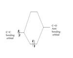
The secondary orbital interaction is a class of electronic effect which can be rationalized here as the interactions between C=C π orbital and the C=O π* orbital as they have both correct symmetry and orientation. The resultant effect can stabilize the system by trading off the weakening the C=O double bond.
The secondary orbital overlap effect had been neglected in the AM1 calculation because the endo transition structure is higher in energy than than of exo transition structure, which contradicts with the experimental observations. As in reality, the endo product predominate over hermodynamically more stable exo productthe as it is the kinetically favorable product unless thermodynamical condition is applied. This is due to the secondary orbital overlap effect in the endo form transition state, such effect can stabilize the endo transition structure and provide a lower energy pathway for the reaction to proceed despite the fact that the exo product is thermodynamically more stable as it has less strain compare the to the endo product.
Reference:
- Yi Li, K. N. Houk J. Am. Chem. Soc., 1993, 115 (16), pp 7478–7485
- Shogo SakaiJ. Phys. Chem. A, 2000, 104 (5), pp 922–927
- Fleming, Ian Pericyclic reactions : Oxford University Press 1998

