Rep:Mod:clc09mod3
Year 3 Computational Chemistry: Chew Chee Leong
Module 3
Introduction
In this module, we learn to characterise transition structures on potential energy surfaces for the Cope rearrangement and Diels Alder cycloaddition reactions. Since the focus is on the transition structures of larger molecules, there are no longer suitable formulae for the energy, and the molecular mechanics / force field methods that work well for structure determination cannot be used as they do not describe bonds being made and broken, and changes in bonding type / electron distribution. Therefore, the new solution involves molecular orbital-based methods, numerically solving the Schrödinger equation, and locating transition structures based on the local shape of a potential energy surface. In addition to transition structures, reaction paths and barrier heights are also calculated.
Part 1: The Cope Rearrangement Tutorial
In this tutorial we will use the Cope rearrangement of 1,5-hexadiene as an example of how to study a chemical reactivity problem. The objectives are to locate the low-energy minima and transition structures on the C6H10 potential energy surface, to determine the preferred reaction mechanism.
Diagram 1: Cope Rearrangement
Optimizing the Reactants and Products
Ten possible conformers of 1,5-hexadiene were subjected to optimisation via the HF/3-21G method, followed by re-optimisation using the B3LYP/6-31G(d) method. At the same level of theory, a frequency calculation was performed. In addition to that, the corresponding energies of conformers were determined. Note that the conformers readily inter-convert at room temperature by means of C-C sigma bond rotation.
| Conformer | Structure | Point Group | HF/3-21G Optimisation | B3LYP/6-31G(d) Re-optimisation | Σ (Eelec + ZPE) | Σ (Eelec + Etherm) | Σ (Helec + Htherm) | Σ (Gelec + Gtherm) |
|---|---|---|---|---|---|---|---|---|
| Gauche 1 | C2 | -231.68771604 | -234.60787891 | -234.465253 | -234.458119 | -234.457175 | -234.495483 | |
| Gauche 2 | C2 | -231.69166700 | -234.61070757 | -234.468206 | -234.460939 | -234.459995 | -234.499103 | |
| Gauche 3 | C1 | -231.69266120 | -234.61132934 | -234.468693 | -234.461464 | -234.460520 | -234.500105 | |
| Gauche 4 | C2 | -231.69153030 | -234.61048196 | -234.467784 | -234.460521 | -234.459577 | -234.498690 | |
| Gauche 5 | C1 | -231.68961572 | -234.60911048 | -234.466369 | -234.459214 | -234.458270 | -234.497439 | |
| Gauche 6 | C1 | -231.68916017 | -234.60888834 | -234.466281 | -234.459103 | -234.458159 | -234.497369 | |
| Anti 1 | C2 | -231.69260236 | -234.61180037 | -234.469286 | -234.461965 | -234.461021 | -234.500162 | |
| Anti 2 | Ci | -231.69253528 | -234.61170280 | -234.469212 | -234.461856 | -234.460912 | -234.500821 | |
| Anti 3 | C2h | -231.68907065 | -234.60964388 | -234.466992 | -234.459816 | -234.458872 | -234.497337 | |
| Anti 4 | C1 | -231.69097055 | -234.61078875 | -234.468193 | -234.460941 | -234.459997 | -234.499482 |
Note
Σ (Eelec + ZPE): denotes potential energy at 0 K including the zero-point vibrational energy.
Σ (Eelec + Etherm): denotes energy at 298.15 K and 1 atm of pressure, including contributions from translational, rotational & vibrational energy modes
Σ (Helec + Htherm): denotes additional correction for RT (H = E + RT).
Σ (Gelec + Gtherm): denotes entropic contributions to the free energy (G = H - TS)
| Conformer | DOI [HF/3-21G] | DOI [B3LYP/6-31G(d)] | DOI [Freq] |
|---|---|---|---|
| Gauche 1 | DOI:10042/to-12368 | DOI:10042/to-12373 | DOI:10042/to-12379 |
| Gauche 2 | DOI:10042/to-12361 | DOI:10042/to-12374 | DOI:10042/to-12380 |
| Gauche 3 | DOI:10042/to-12360 | DOI:10042/to-12375 | DOI:10042/to-12381 |
| Gauche 4 | DOI:10042/to-12362 | DOI:10042/to-12376 | DOI:10042/to-12382 |
| Gauche 5 | DOI:10042/to-12363 | DOI:10042/to-12377 | DOI:10042/to-12383 |
| Gauche 6 | DOI:10042/to-12364 | DOI:10042/to-12378 | DOI:10042/to-12384 |
| Anti 1 | DOI:10042/to-12365 | DOI:10042/to-12369 | DOI:10042/to-12385 |
| Anti 2 | DOI:10042/to-12359 | DOI:10042/to-12370 | DOI:10042/to-12386 |
| Anti 3 | DOI:10042/to-12366 | DOI:10042/to-12371 | DOI:10042/to-12387 |
| Anti 4 | DOI:10042/to-12367 | DOI:10042/to-12372 | DOI:10042/to-12388 |
In terms of energy, the HF/3-21G method predicted Gauche 3 to be the most stable conformer whereas the B3LYP/6-31G(d) method suggested otherwise; Anti 1 is found to be most stable. Since the B3LYP/6-31G(d) method is more sophisticated than the 'primitive' HF/3-21G, Anti 1 is overall the most stable conformer at room temperature.
Optimizing the "Chair" and "Boat" Transition Structures
In this section, the "chair" and "boat" transition structures for the Cope rearrangement were optimised by computing the force constants at the beginning of the calculation, (2) using the redundant coordinate editor, and also (3) QST2. In addition, we attempt to visualize the reaction coordinate, run the IRC (Intrinsic Reaction Coordinate) and compute the activation energies for the Cope rearrangement via the "chair" and "boat" transition structures.
Chair TS: Optimization to a TS (Berny)
The allyl fragments of the guess structure were positioned 2.20075Å apart. The optimisation process was successful; an imaginary vibrational frequency at -818.02cm-1 was found and its vibrational mode can be observed HEREDOI:10042/to-12389 . After optimisation, the distance between the terminals has decreased to 2.02029Å and the fragments appeared slightly bent.
Chair TS: Optimization via Frozen coordinate method
This method was unique in the sense that the terminal ends were "frozen" at a distance of 2.20075Å using the Redundant Coord Editor and optimised. When the job is done, the fragments were "unfrozen" and optimised again. The separation between the two terminal ends was 2.19999Å for the frozen structure and 2.02037Å for the unfrozen structure. The final conformations were nearly identical, suggesting both methods were in good agreement with each other. ( DOI:10042/to-12390 ; DOI:10042/to-12391 )
Boat TS : QST2 Method
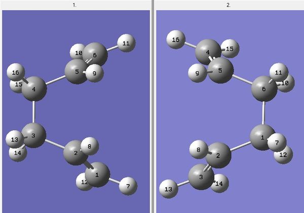
Using an optimised Anti 2 conformer, a pair of Reactant and Product conformers were modelled. All the atomic labels have been changed. For the boat transition state to be located, the central C-C-C-C dihedral angle was changed to 0o, while the central C-C-C were reduced to 100o.
Diagram 2: 1 = Reactant, 2 = Product
After arranging the atoms in a specific way, the structures were optimised using the method below:
opt=qst2 freq hf/3-21g geom=connectivity
Another imaginary vibrational frequency at -839.98cm-1 was found and its vibrational mode is animated HEREDOI:10042/to-12402 . The distance between the two terminal ends was 2.15000Å, which is slightly longer than the chair transition state.
Intrinsic Reaction Coordinate (IRC) Analysis
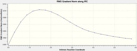
To verify whether the above transition states were fully optimised, the IRC method is helpful where it uses the imaginary vibrational mode found in the frequency analysis above to determine energetic stability in steps. This gives a good indication on whether the transition state is at the maximum of an energy diagram.
Optimized chair transition structure
| Final Conformation of Chair TS | Total Energy | RMS Gradient |
|---|---|---|
 |
 |
Optimized boat transition structure
| Final Conformation of Boat TS | Total Energy | RMS Gradient |
|---|---|---|
 |
 |
Activation energies
The activation energies were solved by taking the difference in energy, ΔE, between the energies of the transition state (the maximum) and the energies of anti 2 (the minimum). Σ (Eelec + ZPE) gave the energy difference, i.e. the activation energy, at 0 K and Σ (Eelec + Etherm) gave the energy difference at 298.15 K.
| HF/3-21G: ChairDOI:10042/to-12418 and BoatDOI:10042/to-12417 TS | DFT B3LYP/6-31G(d): ChairDOI:10042/to-12415 and BoatDOI:10042/to-12416 TS | |||||
|---|---|---|---|---|---|---|
| Transition State | Electronic Energy | Σ (Eelec + ZPE) | Σ (Eelec + Etherm) | Electronic Energy | Σ (Eelec + ZPE) | Σ (Eelec + Etherm) |
| Chair TS | -231.61952 | -231.46570 | -231.46234 | -234.55697 | -234.41483 | -234.39901 |
| Boat TS | -231.60280 | -231.45093 | -231.44530 | -234.56309 | -234.40241 | -234.39601 |
| Anti 2 conformer | -231.69254 | -231.53954 | -231.53257 | -234.61174 | -234.46931 | -234.46086 |
Activation Energies /kcalmol-1
| HF/3-21G | DFT B3LYP/6-31G(d) | |||
|---|---|---|---|---|
| @ 0 K | @ 298.15 K | @ 0 K | @ 298.15 K | |
| ΔE Chair | 46.68 | 44.66 | 34.56 | 33.49 |
| ΔE Boat | 57.09 | 54.88 | 42.74 | 41.97 |
Part 2: The Diels Alder Cycloaddition
Optimisation of cis-butadiene and molecular orbitals
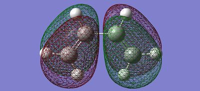
Using Gaussview, a cis-butadiene molecule was drawn and then optimised using the AM1 Semi-empirical method. Its molecular orbitals in the HOMO-LUMO region and symmetry were also elucidated.
| Molecular Orbital | Front View | Bird's eye View | Symmetry in Horizontal Plane | Symmetry in Vertical Plane |
|---|---|---|---|---|
| LUMO | 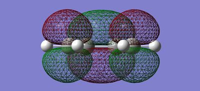 |
 |
Antisymmetric | Symmetric |
| HOMO |  |
 |
Antisymmetric | Antisymmetric |
Optimisation of transition state of cis-butadiene and ethene
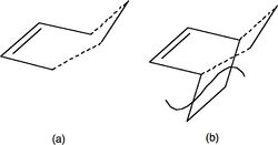
In order to construct a transition state model between the reaction of cis-butadiene and ethene, we have to build a starting geometry. This is done by building a bicyclo system (b) and then remove the -CH2-CH2- fragment. The inter-fragment distance (dashed lines) was initially guessed to be 2.50000Å prior to optimisation. The starting geometry was then optimised via the following command:
# opt=(calc,ts) freq rb31yp/6-31g(d) geom=connectivity
Diagram 3: Constructing the starting geometry
Result
HOMO and LUMO Sketch
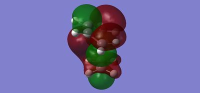
| Molecular Orbital | Front View | Side View | Symmetry in Horizontal Plane | Symmetry in Vertical Plane |
|---|---|---|---|---|
| LUMO | 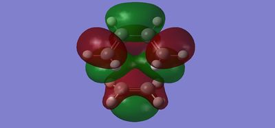 |
 |
Antisymmetric | Symmetric |
| HOMO |  |
 |
Antisymmetric | Antisymmetric |
The HOMO of the Transition State is a combination of the HOMO of cis-butadiene and the LUMO of ethene whereas the LUMO of the Transition State consists of the LUMO of cis-butadiene and the HOMO of ethene. This finding is consistent with the symmetries observed; the HOMO of TS is antisymmetric since it is made from two antisymmetric MO's, while the LUMO of TS is symmetric due to two symmetric MO's[1].
Geometry of the transition structure
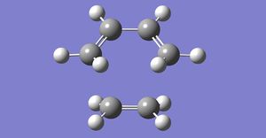
| Optimised Transition State |
|---|
|
After optimisation DOI:10042/to-12546 , the bond-lengths of the partly formed σ C-C bonds were found to be 2.27251Å. The typical sp3 and sp2 C-C bond lengths are 1.50Å [2]. while the Van der Waals radius of a carbon atom is 1.70Å. The partly formed σ C-C bond in the TS is longer than the typical sp3 and sp2 C-C bond by 0.77251Å, suggesting the bond formation is still on its way to completion.
Frequency analysis
An imaginary frequency was found at -524.81cm-1, which corresponded to the reaction path at the transition state. Reaction proceeded in a Syn fashion. Click HERE to view the vibrational mode. The lowest positive frequency (135.84cm-1) displayed wagging, which had little to do with the reaction pathway. However, the vibrational mode at 284.48cm-1 bore some resemblance to the reaction pathway.
The regioselectivity of the Diels Alder Reaction
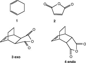
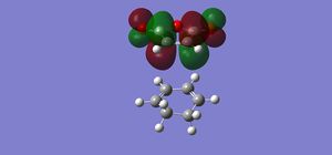
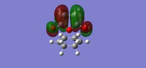
The cycloaddition reaction between cyclohexa-1,3-diene and maleic anhydride produces two isomers; endo and exo. The major product is the endo adduct. Assuming the reaction is under kinetic control, the exo transition state will therefore be higher in energy.
Optimisation of transition states
The transition states were optimised via the semi-empirical AM1 method:
Molecular Orbitals
| Conformation | HOMO | LUMO |
|---|---|---|
| Endo | 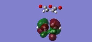 |
|
| Exo |  |
|
Vibrational analysis
| Conformation | Imaginary Frequency (cm-1) | Vibrational Mode | DOI |
|---|---|---|---|
| Endo | -19.92 | Animate | DOI:10042/to-12547 |
| Exo | -29.52 | Animate | DOI:10042/to-12548 |
Intrincsic Reaction Coordinate analysis
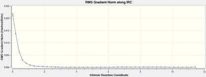
The IRC method (forward) was performed to verify the complete optimisation of the transition states.
| Isomer | Total Energy | RMS Gradient | Final Conformation |
|---|---|---|---|
| Endo DOI:10042/to-12555 |  |
 |
|
| Exo DOI:10042/to-12554 |  |
 |
The transition states were well optimised, given the RMS gradient graphs of both endo and exo isomer displayed an asymptote.
Relative Energies of the transition states
The relative energies of the transition states were as follows:
| Isomer | Relative Energy (AM1)/Eh | Final Isomer | Relative Energy (AM1)/Eh |
|---|---|---|---|
| Endo | -0.051867 | IRC Forward: Step 46 | -0.160631 |
| Exo | -0.050577 | IRC Forward: Step 39 | -0.156809 |
The endo transition state was lower in energy than the exo transition state; meaning it is the thermodynamically more stable product.
References
- ↑ Fernando. Bernardi, Andrea. Bottoni, Martin JField, Martin F. Guest, Ian H. Hillier, Michael A. Robb, Alessandro. Venturini J. Am. Chem. Soc., 1988, 110 (10), pp 3050–3055Template:DOI10.1021/ja00218a009
- ↑ Fox, Marye Anne; Whitesell, James K. (1995). Organische Chemie: Grundlagen, Mechanismen, Bioorganische Anwendungen. Springer. ISBN 9783860252499


