Rep:Mod:boulty3
Module Three - Transition States and Reactivity - The Cope Rearrangement
This module will consider the characterization of transition structures on potential energy surfaces for the Cope rearrangement. The reaction in question will be the [3,3] sigmatropic shift reaction of 1,5-hexadiene shown below. Molecular mechanics do not work well and we can no longer use fitted functions and formulae for the energy calculations in the system. These methods do not describe bonds being made or bonds being broken and changes in bonding type or electron distribution. This module uses MO based methods and in doing so numerically solves the Schrodinger equation. The transition states within the structure are located based on the local shape of a potential energy surface. The MO based method also allows reaction paths and barrier heights to be calculated. The objectives for this experiment are as follows:
- locate low energy minima and transition structures on 1,5-hexadiene potential energy surface
- determine the preferred reaction mechanism

The mechanism of the Cope Rearrangement was a subject of deep controversy but it is now accepted that the method is a concerted process which can proceed through one of two different transition type structures: the boat or chair transition structure. Both of these transition structures will be fully investigated to decide which is the most favourable for this reaction to proceed through. It is generally accepted that the boat structure lies several kcal/mol higher in energy than the chair transition structure. To analyse these structures the B3LYP/6-31G method and basis set is sufficient to provide good results which are in agreement with that obtained experimentally.

Optimising the Structures
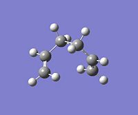
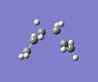
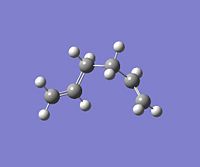
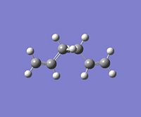
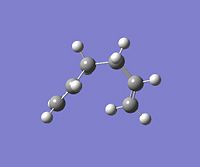
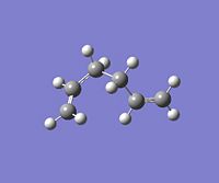
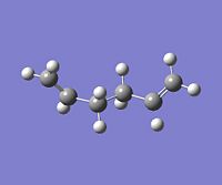
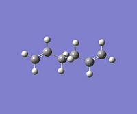
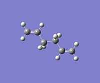
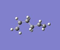
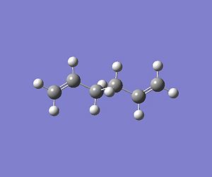
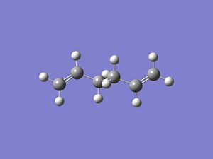
Using GaussView, a moleucle of 1,5-hexadiene was drawn with an "anti" linkage, whereby all the bonds are trans to each other. The structure was first cleaned using the option in the toolbar of GaussView and then optimised at the HF (Hartree Fock)/3-21G level. The resulting energy of the optimization was -231.68540 a.u., with the symmetry of the molecule being assigned to the C2h point group.DOI:10042/to-4702 . From Appendix 1[1], this conformer was assigned to be "anti-3". All of the other conformations were then found and optimised using the same method and basis set. NB: Relative energies were calculated in kcal/mol by the conversion factor of 1 Hartree = 627.51 kcal/mol
| Conformer | Structure | Point Group | Energy/Hartrees HF/3-21G | Relative Energy to gauche-3 /kcal/mol | DOI |
|---|---|---|---|---|---|
gauche-1 |
C2h |
-231.68772 |
3.10 |
||
gauche-2 |
C2 |
-231.69167 |
0.62 |
||
gauche-3 |
C1 |
-231.69266 |
0.00 |
||
gauche-4 |
C2 |
-231.69153 |
0.71 |
||
gauche-5 |
C1 |
-231.68962 |
1.91 |
||
gauche-6 |
C1 |
-231.68916 |
2.20 |
||
anti-1 |
C2 |
-231.69260 |
0.04 |
||
anti-2 |
Ci |
-231.69253 |
0.08 |
||
anti-3 |
C2h |
-231.68540 |
4.56 |
||
anti-4 |
C1 |
-231.69097 |
1.06 |
As the anti-2 structure matched that in Appendix 1[2] in terms of energy and symmetry, the conformer was optimised to a more in depth basis set using a different method. The DFT B3LYP/ 6-31G(d) level was used with the resulting energy output being -234.61171 a.u DOI:10042/to-4718 . The energies computed from both methods cannot be compared as two different methods with two different basis sets were used. However, we can compare the geometry ouptut from both methods.
| Optimised Geometry HF/3-21G | Optimised Geometry DFT B3LYP/6-31G | Experimental | |
|---|---|---|---|
C=C bond length /A |
1.32 |
1.33 |
1.34[1]
|
C-H bond length /A |
1.07 |
1.09 |
1.09[2]
|
C-C bond length /A |
1.51 |
1.50 |
1.52[3]
|
From the table above, it is clear to see that the geometry of the anti-2 conformer using both levels of optmisation produces the same geometry for the conformer. This shows that the level of optimisation required for thse calculations is very low, and a higher level basis set does not need to be used to reproduce experimental data. This is shown by the measured bond lengths in both optimisations being very similar to that obtained experimentally.
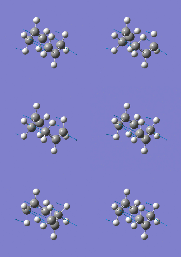
The energies given in the output filees for each optimisation represent the energy of the conformer on a bar potential energy surface. To compare experimentally measured quantities, more terms in the calculation must be included. A frequency calculation will be undertaken with the ouput of this calculation being used to characterise critical points within the transition state structure i.e. to confirm that it is a minimum in this case: that all vibrational frequencies are real and positive. The frequency calculations were run at the same level of theory as the higher optimisation of the "anti-2" strucure - DFT B3LYP/6-31G method . For the "anti-2" structure, the frequency analysis was undertaken which resulted in no imaginary frequencies of vibration being calculated DOI:10042/to-4719 . This shows that a valid minimum has been found. The resulting IR spectrum is shown below, with the three most intense vibrations animated:
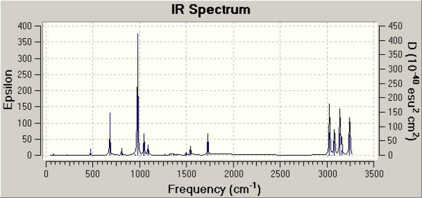
| Vibration Number | Animated Vibration | Frequency of Vibration / cm-1 | Intensity |
|---|---|---|---|
14 |
977 |
164
| |
34 |
3139 |
60
| |
38 |
3028 |
60
|
The log file for the calculation was then opened and the section considering the thermochemistry of the optimisation located. Under the vibrational temperatures a list of energies were present which are as follows:
- the sum of electronic and zero-point energies = -234.41624 a.u. This energy is the potential energy at 0 K including the zero-point vibrational energy (E = Eelec + ZPE)
- the sum of electronic and thermal energies = -234.40895 a.u. This is the energy at 298.15 K and 1 atm of pressure which includes contributions from the translational, rotational, and vibrational energy modes at this temperature (E = E + Evib + Erot + Etrans)
- the sum of electronic and thermal enthalpies = -234.40801 a.u. This energy contains an additional correction for RT (H = E + RT)
- the sum of electronic and thermal free energies = -234.44784 a.u. This energy includes the entropic contribution to the free energy (G = H - TS)
The first and second quantities on the list above will be used later on to quantify the transition state barrier (activation energy) for the "chair" and "boat" transition state structures.
Optimising the "Chair" and "Boat" Transition Structures
The aim of this part of the experiment is as follows:
- set up transition state structure optimizations and compute force constants
- use the redundant co-ordinate editor and the QST2 method
- visualize the reaction co-ordinate and run the IRC
- calculate activation energies for the Cope Rearrangement via the "chair" and "boat" transition structures
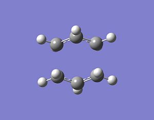
Theoretically, the chair and boat structures of the transition states consist of two C3H5 allyl fragments. Therefore, two fragments will be used to model these transition states. and will be placed approximately 2.2A apart from each other in the desired conformation. The chair transition structure has C2h symmetry whereas the boat structure has C2v symmetry. A C3H5 fragment was drawn into GaussView and optimised using HF/3-21G level of theroy which resulted in the fragment being optimised to an energy of -115.82304 a.u DOI:10042/to-4711 . This optimised structure was then copied into a new window to give two optimised C3H5 allyl fragments. These optimised fragments were then arranged into a chair like transition state with the central carbon of each fragment pointing in opposite directions making sure the distance between each terminal carbon of oposite fragments being approximately equal to 2.2A. In general, transition state optimisations are more difficult to undertake than minimizations because the calculation needs to be where the negative direction of the reaction co-ordinate is, otherwise the incorrect structure could be located. With a reasonable guess of the transtion state, the force constants for the optimisation process can be computed. With the computation of these force constants, GaussView can easily identify whether it is moving in the correct direction to locate the correct optimised transition state structure. With the two fragments being arranged in a chair like transition structure, they were optimised at the HF/3-21G level of theory with accompanying frequency calculations (Opt+Freq). This time the optimisation was not to a minimum structure but a TS(Berry) which can be selected as an option in Gaussview. The optimisation resulted in the transition state shown below, with the frequency output only showing one imaginary frequency of -817.93cm-1DOI:10042/to-4714 . The imaginary frequency and transition state structure obtained are consistent with those shown in Appendix 2 [3]. The vibration is also animated below.
The transition state structure can also be optimised using a frozen co-ordinate method. The guess structure for the "chair" transition stae was used again but instead of doing a normal optimisation, the redundant co-ordinate editor was used. The redundant co-ordinate editor aloows us to fix the distances between the terminal carbons which are involved in the transition state bond making process. Bonds between terminal carbons were set to be 2.2A and a normal calculation was set up using the HF/3-21G level of theory DOI:10042/to-4715 . The resulting .chk file was accessed after the calculation had finished and these bond lengths had been optimised to approximately 2.2A. The redundant method was used again to optimise the structure that has just been optimised. The two sets of bond forming/breaking carbons were set to derivatives with the same calculation set up. This time the force constants were not calculated DOI:10042/to-4716 . Comparing this further optimised structure to the HF/3-21G optimised chair structure, the main difference is the symmetry of both structures. The HF/3-21G structure has a point group of C2h and this is reduced to Ci in the redundant co-ordinate editor method. The bond lengths between termianl carbons is approximately the same at around 2.02A with the energy of the system also remaining constant at -231.61932 a.u. This shows that both methods can allow us to assess the energetics of the system in question but they have contrasting results concerning the overall symmetry of the system.
The "boat" structure was based on the structure obtained for "anti-2" (from the B3LYP/6-31G level optimised structure) and optimised using the QST2 level of theory. The QST2 method allows you to input structures for your reactant and your product, which are the same molecule in this Cope Rearrangement, but the numbering of the systems will be different. The QST2 method will locate the transition state by moving between these two structures. It is important that the products and reactants were numbered in the same way (i.e. the carbon number on the reactant matching the same carbon number on the product). This process was carried out numerous times due to this labelling not being correct. Manual editing using the atom list editor took place to ensure that all labeling in the reactants and products were identical (shown below). A TS(QST2) calculation was set up using the HF/3-21G level of theory. However this job did not converge to the correct transition structure. The transition structure obtained is just a rotation of one of the allyl fragments with respect to the other fragment. Even at higher levels of theory (HF/6-31G and DFT B3LYP/6-31G), the QST2 method did not converge to the correct structure. Therefore the reactant and product geometries were modified so that they had more of a ressemblence of the boat transition structure. To achieve this, the dihedral angles were optimised in both product and reactant geometries. The dihedral angle for the central four carbons in each molecule were optimised from 180 degrees to 0 degrees, with the internal angle of the resulting structure being optimised from around 113 degrees down to 100 degrees. This resulted in the reactant and product geometries as follows:
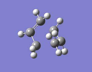
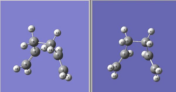
This geometrically optimsed structure was then set for Opt+Freq analysis using the QST2 method and the HF/3-21G level of theory. This converged to the desired boat structure with one imaginary frequency at around -840cm-1, which is animated below:DOI:10042/to-4723 . The QST3 method can also be used to achieve more reliable results which allows you to input the geometry of the guess transition state. This will not be shown however due to time constraints.
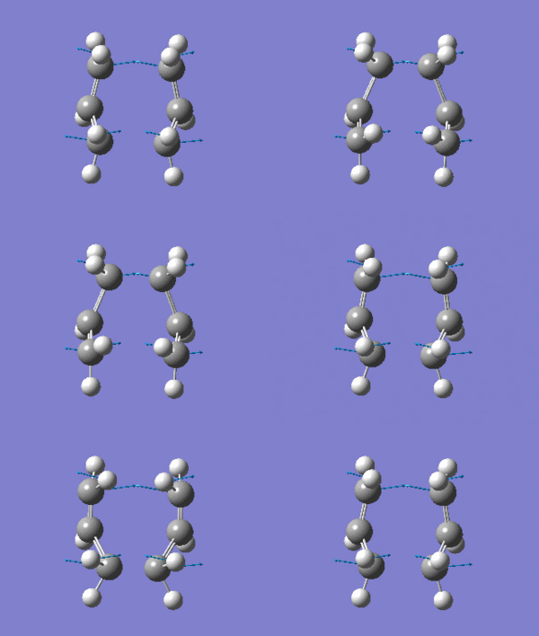
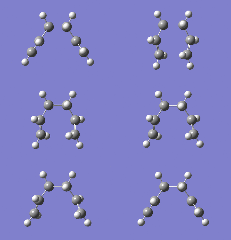
The "boat" and "chair" transition states have been succesfully found but we do not know which one the reaction proceeds through. The intrinsic reaction co-ordinate (IRC) creates a series of points by taking small geometry steps in the direction where the energy gradient is steepest. The IRC calculation will be performed on both transition state structures, calculating the force consants once. The IRC was only computed in the forward direction to the symmetrical nature of the reaction. The higher level optimisation of the "chair" structure was taken (DFT B3LYP/6-31G) and the IRC calculation was set up calculating the force consatnts once. From the results, the molecule hasn't reached a minimum geometry so the calulcation procedure can be changed in the followung three ways to enahnce the minimsation.
- take the last point on the IRC and run a normal minimization
- specify a larger number of points until it reaches a minimum
- compute the force constants at every step
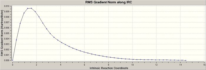
There are advantages and disadvantages to using each of these methods. I decided to specify a larger number of points in the input file until it reached a minimum. The script suggested trying 50, but I decided to use 100 points in the calculation to make sure a minimum was achieved DOI:10042/to-4736 . The risk in this method is using too many points with the calculation veering off in the wrong direction, not locating the minima. The resultant RMS Gradient along the IRC path and the Total Energy plots for the chair transition strucutre are shown below, where the structure converged in 47 steps. The two plots show that the IRC reached a minimum energy, with little change in the geometry of the optimised species in comparison with the other previously used optimisation processses. The IRC convergance looks very similar to the gauche-2 conformer that has already been established in earlier calculations.

The activation energy to reach each transition structure can alos be considered. Calculations were run on the HF/3-21G transition state structures up to a higher level of theory of B3LYP/6-31G*, running an optimisation and frequency calculation. The sum of the electronic and thermal energies represents the energy at 298.15K and the sum of the electronic and zero point energies represents the energy at 0K. To find the activation energy for the boat and chair transition structures, the difference was calculated between the "anti-2" conformation and the "boat/chair" conformations at 0K and 298.15K, with the results shown below in the Summary of Results section of the report. The calculated activation energies are in very good agreement with those given by Appendix 2. Comparing the two different calculation methods, it is clear to see that both methods give a good estimate on the activation energy for each transition state with the higher level basis set giving a higher degree of precision than the lower level basis set. However it must be noted that is better to calculate the energy a a lower level basis set first (HF/3-21G), then recalculate it using a higher level basis set (B3LYP/6-31G). The results show experimentally, that the chair transition state has a lower activation energy compared to the boat transition state which was expected. The calculated energy difference between the two conformers at 0K is 7.89 kcal/mol which is in average agreement with the value obtained experimentally 5.5 kcal/mol. The conclusions that can be drawn from this are that the B3LYP model can be used to good effect to model the transition state structures and vibrations, but the activation energy may require a more in depth basis set.
Summary of Results
Summary of energies (in hartree)
HF/3-21G |
B3LYP/6-31G*
| |||||
Electronic Energy |
Sum of Electronic and Thermal Energies at 298.15K |
Sum of Electronic and Zero Point Energies at 0K |
Electronic Energy |
Sum of Electronic and Thermal Energies at 298.15K |
Sum of Electronic and Zero Point Energies at 0K
| |
-231.61932 |
-231.46134 |
-231.46670 |
-234.55698 |
-234.40901 |
-234.41493
| |
-231.60280 |
-231.44530 |
-231.45093 |
-234.54309 |
-234.39601 |
-234.40235
| |
-231.69254 |
-231.53257 |
-231.53954 |
-234.61171 |
-234.46186 |
-234.46920
| |
*1 hartree = 627.509 kcal/mol
Summary of activation energies (in kcal/mol)
HF/3-21G at 0K |
HF/3-21G at 298.15K |
B3LYP/6-31G* at 0K |
B3LYP/6-31G* at 298.15K |
Experimental at 0K
| |
ΔE chair |
45.70 |
44.69 |
34.05 |
33.16 |
33.5 ± 0.5
|
ΔE boat |
55.60 |
54.76 |
41.95 |
41.32 |
44.7 ± 2.0
|

