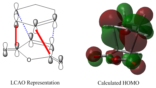
Rep:Mod:asartor111physical
Cope Rearrangement
This section studies the Cope rearrangement of 1,5-hexadiene. The Cope rearrangement, first reported in 1940[1], is a pericylic reaction often observed in systems that have a 1,5-diene motif. In the example studied, the system is completely symmetric, resulting in a product identical to the reactant:

|
However, if there are substituents present on the system, the reactants and products will not be the same, and thermodynamic effects must be considered in determining which would be the major component of an equilibrium system.
As shown by the mechanism above, the reaction is expected to proceed via an aromatic transition state involving 6 electrons. It thus matches the '4n+2' rule and will proceed via a Hückel transition state when initiated under thermal conditions, as per the Woodward-Hoffman rules[2].
Initial Reactant Optimisations
| Anti 1,5-hexadiene | |
|---|---|
|
|
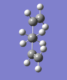
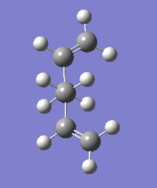
| Starting geometry for anti conformer | Optimised geometry (HF 3-21G) |
A conformer of 1,5-hexadiene was drawn in GaussView by placing an ethyl fragment and then replacing two hydrogen atoms with vinyl fragments, and then performing a 'Clean' operation. This structure was optimised using the HF method to the 3-21G level. The calculated energy was -231.69260235 a.u.. The 'Symmetrize' functionality assigned the C2 point group. The pictures below show the starting and final geometries, viewed along the C3-C4 bond.
| Gauche 1,5-hexadiene | |
|---|---|

|

|
| Starting geometry for gauche conformer | Optimised geometry (HF 3-21G) |
The starting geometry of the anti arrangement was turned into a gauche arrangement by editing the dihedral angle of the central four carbon atoms and then performing a 'Clean' operation. The same optimisation was performed. The energy was expected to be higher, because the gauche conformer has the two more bulky vinyl groups closer to each other in space, allowing unfavourable steric interactions. This was indeed the case; the calculated energy was -231.69166701 a.u., higher than the anti conformer by 0.00093534 a.u. or 2.5 kJmol-1. The 'Symmetrize' functionality assigned the same C2 point group.
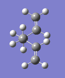
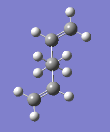
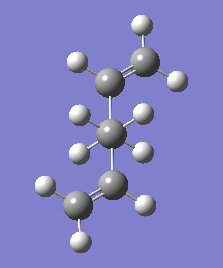
Visual inspection of the two conformers above shows that both have the vinyl groups pointing towards each other in the plane of the page. It is possible that the structures would be more stable with them pointing away from each other, as this would result in lessened steric interactions. The anti-conformer with them pointing away from each other (anti-opp) was assumed to be the most stable, but just in case, the gauche-opp conformer was calculated as well.
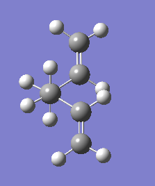
The new starting geometries for the 'opp' (opposing vinyl groups) conformers were created by opening the optimised structures from the above conformers and rotating the vinyl groups through the dihedral angle setting.
| Gauche-opp 1,5-hexadiene | |
|---|---|
|
|
| Starting geometry for gauche-opp conformer | Optimised geometry (HF 3-21G) |
The gauche-opp conformer had a calculated energy of -231.69153035 a.u., which is actually higher in energy than the gauche conformer calculated previously. Its assigned point group is C2.
| Anti-opp 1,5-hexadiene | |
|---|---|
|
|
| Starting geometry for gauche-opp conformer | Optimised geometry (HF 3-21G) |
The anti-opp conformer's energy is -231.69253516 a.u., which is also higher than the previous conformer. It seems that the initial conformer is actually the most stable of the structure. This conformer has the Ci point group.
These results meant that the hypothesis of the anti-opp conformer being the most stable conformer was incorrect. So far, the most stable conformer is the anti conformer, but one of the five obvious structures remained to be tested.
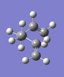
The gauche conformer has been tested with both vinyl groups pointing towards the 'middle' of the picture (with the molecule oriented such that it is viewed along the C3-C4 bond), and with both pointing outwards. One more attempt at finding a more stable conformer was made in the final combination of one vinyl group pointing 'in' and the other pointing 'out'. This conformer was dubbed 'gauche-face', as the vinyl groups face in the same direction.
| Gauche-face 1,5-hexadiene | |
|---|---|

|
 |
| Starting geometry for gauche-opp conformer | Optimised geometry (HF 3-21G) |
Like before, this starting geometry was constructed by opening the optimised gauche-opp conformer and rotating one of the vinyl groups by changing the dihedral angle setting. The optimised structure has an energy of -231.69266121 a.u., which somewhat surprisingly is actually more stable than both of the anti conformers. It is more stable than the anti conformer by -0.00005886 a.u. or 0.15 kJmol-1.
Visual inspection of the geometry (which is possible by pressing 'Load' on the Jmol applet above) shows that the vinyl groups have found an arrangement where the vinyl groups point away from the plane of the page. This does break the symmetry of the conformer, resulting in a C1 point group.
Through the testing of these five immediately obvious candidates for low-energy conformers, it was determined that the most stable form of 1,5-hexadiene is the gauche-face conformer with an energy of -231.69266121 a.u., adopting the C1 point group. The fact that this structure is the most stable can not only be attributed by the lack of steric clash between the vinyl groups, as this is the case to an even greater case in the anti-opp structure. It must be that orbital interactions stabilise this conformer to a greater extent; the orientation is optimal for interactions between the high energy C=C π orbital and the C-H σ* orbital. Several such interactions are possible in the gauche arrangement.
Energy Comparisons
The lab script provided a table containing a range of possible conformers, including all those found above. The following table shows the provided names and energies and compares them to the energies calculated.
| Calculated Conformer | Provided Conformer[3] | Agreement? | ||||
|---|---|---|---|---|---|---|
| Name | Point Group | Energy (a.u.) | Name | Point Group | Energy (a.u.) | |
| Anti | C2 | -231.69260 | anti1 | C2 | -231.69260 | Yes |
| Gauche | C2 | -231.69167 | gauche2 | C2 | -231.69167 | Yes |
| Gauche-opp | C2 | -231.69153 | gauche4 | C2 | -231.69153 | Yes |
| Anti-opp | Ci | -231.69254 | anti2 | Ci | -231.69254 | Yes |
| Gauche-face | C1 | -231.69266 | gauche3 | C1 | -231.69266 | Yes |
All five conformers identified are in perfect agreement in terms of energy (to the number of decimal points used in the provided data) and point group.
Not all possible low-energy conformers provided in the Appendix table were identified above, but those identified were indeed the five lowest-energy ones.
The Anti2 Conformer
Further Optimisation
The anti2 conformer (previously referred to as the 'anti-opp' conformer; the name is adapted from the provided data to make the comparisons easier to follow) was calculated above at the HF/3-21G level to have an energy of -231.69254 a.u., matching the provided energy value. This structure was then optimised further using the B3LYP method and the 6-31G(d) basis set.
This structure's calculated energy at the 6-31G(d) level was -234.61170686 a.u., however, this energy cannot be directly compared to that calculated to HF/3-21G, as energies are dependent on the choice of basis set. The reoptimised structure's point group was still Ci.
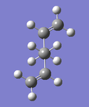
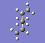
| Anti2 1,5-hexadiene | |
|---|---|
 |
 |
| Optimised to HF 3-21G | Optimised to B3LYP 6-31G(d) |
Both the structure optimised to HF/3-21G and that optimised to B3LYP/6-31G(d) are linked as Jmol applets above. Examination of some key bond lengths and angles (shown in the applet) gives the following data (with C numbering according to IUPAC convention):
| Optimisation Level | Bond Lengths (Å) | Bond Angles (°) | |||
|---|---|---|---|---|---|
| C1-C2 | C2-C3 | C3-C4 | C1-C2-C3 | C2-C3-C4 | |
| HF 3-21G | 1.32 | 1.51 | 1.55 | 124.8 | 111.3 |
| B3LYP 6-31G(d) | 1.33 | 1.50 | 1.55 | 125.3 | 112.7 |
The geometry does not undergo any hugely significant changes upon reoptimisations. The bond lengths remain within 0.01 Å of the initial values. The change is more significant when looking at the C-C-C bond angles; both the C-C-C angle around the sp2 carbon, and that around the sp3 carbon, expand, if only slightly (1.4° and 0.5°, respectively).
Frequency Analysis
To ensure that the structure found in this optimisation step does indeed represent a minimum on the energy surface, a frequency analysis was performed. If the optimisation found a minimum, the frequency analysis run to the same level of theory should contain only real and positive vibrational frequencies.
The two key lines of the .log output file are pasted below:
 Low frequencies ---  -23.2792   -6.7528    0.0005    0.0007    0.0012    2.7446
 Low frequencies ---   72.6092   79.0575  121.6502
The first line represents the translational and rotational modes of the molecule (these should be zero, and come closer to zero for higher levels of theory). The second line represents the lowest vibrational modes; none of these are negative, indicating that the optimised structure is in fact a minimum.
The thermochemical data contained in the .log output file is as follows:
 Sum of electronic and zero-point Energies=           -234.469202
 Sum of electronic and thermal Energies=              -234.461845
 Sum of electronic and thermal Enthalpies=            -234.460901
 Sum of electronic and thermal Free Energies=         -234.500816
The first value is E = Eelec + ZPE (at 0K), and the second is E + Evib + Erot + Etrans, meaning the difference between these two values is the sum of the contributions from the translational, rotational, and vibrational energy modes: 0.007357 a.u..
The difference between the last two terms is -TS = -0.039915 a.u., and so S = 351.5 Jmol-1K-1.
The calculation was run a second time, this time setting the temperature to be 0K. However, examining the .log file revealed that the software still seemed to be using a temperature of 298.15K. After testing different aspects of the input file, this was found to be a function of setting the temperature to be exactly zero - in this case the input was ignored. Setting the temperature to a very low value, here 0.01K, however, resulted in successful calculation at near-zero temperatures. The thermochemical data output at 0.01K was as follows:
 Sum of electronic and zero-point Energies=           -234.469202
 Sum of electronic and thermal Energies=              -234.469202
 Sum of electronic and thermal Enthalpies=            -234.469202
 Sum of electronic and thermal Free Energies=         -234.469202
As expected, there is no variation between the different energies; the temperature is effectively 0 and thus there are no necessary temperature-related corrections.
The low frequencies from this output file are:
 Low frequencies ---  -23.2792   -6.7528    0.0003    0.0004    0.0006    2.7446
 Low frequencies ---   72.6092   79.0575  121.6502
These are as above.
Transition Structures
In a new GaussView window, an allyl group was drawn by placing a vinyl group (giving ethene), replacing one of the hydrogen atoms with a carbon atom, and using the 'add valence' functionality twice to add two hydrogen atoms to this carbon. Finally, the bonds were turned into 'aromatic' bonds (bond order ~1.5, this is mostly for the sake of visualisation). This structure was then optimised to the HF/3-21G level.
The bond lengths had not been changed to being equal in the setup of the geometry. After optimisation, they were, as expected, equivalent, at 1.39 Å. The C-C-C bond angle is 124.3°.
This allyl structure was then used as a building block for the transition state geometries.
Chair Structure
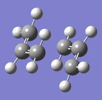
A guess for the chair transition state structure was constructed by pasting the allyl group twice into a new MolGroup file, and then manually rotating and translating one group to create a chair-like structure where the terminal allyl groups were 2.19 Å apart on both sides.
This geometry was used as the starting point for an Opt+Freq calculation using HF/3-21G. The Opt=NoEigen keyword was added to the input file to prevent the calculation from crashing in response to imaginary frequencies. The software was set to optimise to a transition state and calculate the force constants once.
| Chair TS (Hessian Method) | |
|---|---|
 |
|
| Chair transition state geometry | Imaginary frequency, magnitude 818cm-1 |
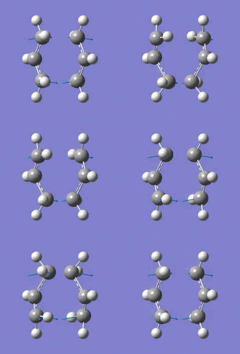
The Jmol applet above shows the resulting structure of the calculation. The optimised structure shows the terminal alkyl groups at a separation of 2.02 Å. The animation shows the vibrational mode associated with the imaginary frequency of magnitude 818cm-1. It does seem to correspond to the Cope rearrangement; the vibration moves between structures where a chain of six carbon atoms is formed across each of the two terminals, where bonds are broken/formed.
The same process was then attempted with a different method. First, the same guess structure was pasted into a new MolGroup file. Two frozen coordinates were defined using the 'Redundant Coordinate Editor' functionality: for each terminal of bond formation/breaking, the two carbon atoms were selected, and the options set to 'Bond'->'Freeze Coordinate'. The structure was then optimised to a minimum, resulting in a chair-like structure with the terminal separations fixed at the initial values. This structure is shown below for reference.
This output .chk file was then edited further by once again using the Redundant Coordinate Editor. The same pairs of carbon atoms were chosen and set to 'Bond'->'Derivative'. This was optimised to a transition state. Again, the Opt=NoEigen keyword was included. This time, the software was set to never calculate the force constants (as this is the point of the frozen coordinate method). When attempting to open the .chk file, this error message was shown. This seemed to be a bug with the software that consistently happened when performing this series of operation. The .log output file opened without issues, and this contained all necessary information.
| Chair TS (Frozen Coordinate Method) | |
|---|---|
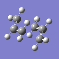 |
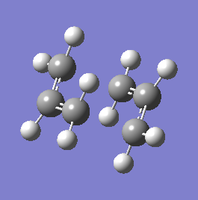 |
| Intermediate geometry (fixed terminal separations) | Optimised geometry |
The two different methods resulted in very similar geometries, with separations of 2.02 Å between the terminal carbon atoms. In both structures, the H-C-C-H dihedral angle between the carbon termini is 56.5°, and the C-C-C bond angle is 120.5° within each allyl fragment and 101.9° at the terminal carbons.
Boat Structure
To find the boat transition structure, a different method was used.
First, the anti2 1,5-hexadiene structure that had previously been optimised to B3LYP/6-31G(d) was copied into a new MolGroup. The 'Add to Molecule Group' functionality was used to paste in a second, separate, identical molecule. The atom number tags were edited so that the numbering matched what would be expected from the reactant and product molecules of the cope rearrangement according to the following scheme:
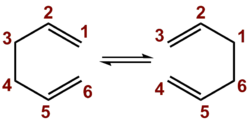
The edited structure looked like this. This was then used to create an input file with the software set to optimise to a transition state. The method chosen was TS(QST2), which uses the two structures from the input and tries to find the transition state between them.
| Boat TS (QST2) |
|---|
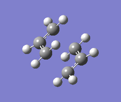 |
| Output from crashed QST2 calculation |
The calculation crashed. Opening the .log output file in GaussView revealed the above structure (click 'Load' to see the 3D representation) which seems to closely resemble the chair transition state found earlier. To encourage the software to instead find the boat transition state, the input was edited to represent a more appropriate geometry for the reaction such that both the reactant and the product are in a similar geometry to the boat-like transition state. The C-C-C-C dihedral angle along the middle C-C bond was set to 0°, and both C-C-C angles were set to 100°. Running this calculation then gave the following result (click 'Load' for 3D representation):
| Boat TS (QST2) | |
|---|---|
 |

|
| Boat transition state geometry | Imaginary frequency, magnitude 840cm-1 |
The animation represents the only imaginary frequency, which has a magnitude of 840cm-1. Again, it visibly corresponds to the Cope rearrangement, with bonds being broken/formed between carbon pairs 1/6 and 3/4. The terminal carbons are 2.14 Å apart, which is a larger separation than in the chair structure case - this makes sense as the boat structure suffers from greater steric clash through eclipsed groups.
IRC
It is very difficult to figure out which conformers of 1,5-hexadiene the transition structures calculated above correspond to by simply looking at them. This prediction was thus performed for the lower-energy chair transition state using the IRC (Intrinsic Reaction Coordinate) method.
As a starting point, the chair geometry previously found by the Hessian method to HF/3-21G was used. The IRC calculation was then set up to run forward (i.e. from the given transition state to the products), calculating the force constants at every step, for a maximum of 50 steps. At first, the run was unsuccessful, giving an error message relating to an error in reading a checkpoint file - the software seemed to have automatically added in unwanted keywords telling the program to search for a checkpoint file to read input data from. These keywords were deleted and the run was repeated successfully.
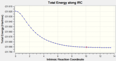
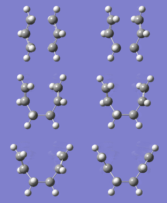
The following shows the energy plot along the reaction coordinate, as well as an animation of the reaction. The list of energies for each step can be found here.
| IRC N=50 | ||
|---|---|---|
 |
| |
As the plot shows, the conformation reached represents an energy minimum - the energy plot is flat at the final step. Of the maximum 50 steps, only 44 were needed to reach the minimum.
| Chair IRC |
|---|
 |
| Minimum found by optimising last step from IRC N=50 |
For the sake of comparison, the minimum was also located by simply copying the geometry of the final step of the IRC calculation, pasting it into a new MolGroup file, and running a normal optimisation to a minimum. This was a quick process, running in less than 2 minutes, and resulted in a geometry resembling the gauche conformer found above. While this is not the most stable conformer of the system, it is low in energy and a local minimum on the energy surface.
B3LYP/6-31G(d) Calculations
One aim of this exercise is to calculate the activation energies of the reaction paths leading through the two transition states, that is, the energy difference between the transition state and the reactant. To allow this comparison, all structures must be optimised and their energies calculated using exactly the same method and basis set. For this reason, the output files of the HF/3-21G-optimised transition states were used as the starting point for optimisations to the B3LYP/6-31G(d) level, which had previously been used to optimise anti2 1,5-hexadiene.
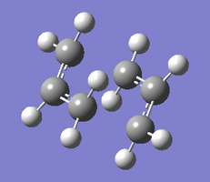
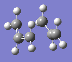
| 6-31G(d) Transition Structures | |
|---|---|
 |
 |
| Chair TS | Boat TS |
The re-optimised structures are linked as Jmol applets above. They are similar in shape to the HF/3-21G approximations, but the terminal carbons are slightly closer together in the case of the chair structure (1.97 vs. 2.02 Å) and slightly further apart in the case of the boat structure (2.21 vs. 2.14 Å).
At the HF/3-21G level, the energy of the anti2 reactant was -231.69253516 a.u., that of the chair transition state -231.61932231 a.u., and that of the boat transition state -231.60280229 a.u.. This suggests activation energies of 46.0 kcal/mol for the chair TS and 56.4 kcal/mol for the boat TS.
At the B3LYP/6-31G(d) level, the energy of the anti2 reactant was -234.61170686 a.u. , that of the chair transition state -234.55698303 a.u. , and that of the boat transition state -234.54309307 a.u.. This suggests activation energies of 34.4 kcal/mol for the chair TS and 43.1 kcal/mol for the boat TS.
The experimental values provided in the script[4] are 33.5 ± 0.5 kcal/mol for the chair transition state and 44.7 ± 2.0 kcal/mol for the boat transition state. This is in much better agreement with the B3LYP/6-31G(d) calculations, suggesting that these are significantly more accurate.
Comparison to experiment may be improved by incorporating solvation into the calculations, and using experimental data observed in the same solvent.
Results Tables
| HF/3-21G | B3LYP/6-31G* | |||||
|---|---|---|---|---|---|---|
| Electronic energy | Sum of electronic and zero-point energies | Sum of electronic and thermal energies | Electronic energy | Sum of electronic and zero-point energies | Sum of electronic and thermal energies | |
| at 0 K | at 298.15 K | at 0 K | at 298.15 K | |||
| Chair TS | -231.6193 | -231.4667 | -231.4613 | -234.5570 | -234.4149 | -234.4090 |
| Boat TS | -231.6027 | -231.4507 | -231.4451 | -234.5431 | -234.4023 | -234.3960 |
| Reactant (anti2) | -231.6925 | -231.5395 | -231.5326 | -234.6117 | -234.4692 | -234.4618 |
Within 3 decimal places, these results agree perfectly with the values provided in the lab script.
| HF/3-21G | B3LYP/6-31G* | Expt. | |||
|---|---|---|---|---|---|
| at 0 K | at 298.15 K | at 0 K | at 298.15 K | at 0 K | |
| ΔE (Chair) | 45.707 | 44.694 | 34.057 | 33.155 | 33.5 ± 0.5 |
| ΔE (Boat) | 55.725 | 54.857 | 41.955 | 41.313 | 44.7 ± 2.0 |
The experimental column is the data provided by the script.
Diels Alder Cycloaddition
This section studies a [2+4] cycloaddition. First the 'prototype' reaction between two unsubstituted reagents is studied, and subsequently a more realistic system involving an electron poor dienophile and a conformationally locked diene (as a key aspect of the Diels Alder reaction is that the diene must be in the s-cis conformation to react).
Prototype reaction: cis-butadiene and ethylene
cis-butadiene
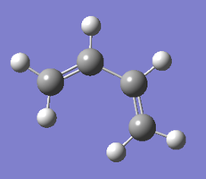
One of the reagents in the cycloaddition reaction to be analysed is cis-butadiene. Its geometry was first drawn in GaussView by inserting a vinyl fragment, replacing one of the hyrdogen atoms with another vinyl fragments, and then changing the C-C-C-C dihedral angle to 0°. This geometry was then optimised using the semi-empirical AM1 method, giving the following structure. It showed C=C bond lengths of 1.34 Å, a C-C bond length of 1.45 Å, and a C-C-C bond angle of 125.7°.
| cis-butadiene (AM1) |
|---|
 |
| Optimised structure |
To further optimise the structure, the B3LYP/6-31G(d) method and basis set were applied (this was the most accurate method used in the above section). This optimisation resulted in a structure with C=C lengths of 1.34 Å, a C-C length of 1.47 Å, and a C-C bond angle of 127.3°. This is in good agreement with reported literature values[5] of 1.337 and 1.46 Å respectively. However, it is not really in better agreement than the AM1 calculation. There is a lack of crystallographic data on the molecule as it polymerises readily, making it difficult to provide more extensive literature comparison including values such as the bond angles. The B3LYP/6-31G(d) was considered as the improved optimisation based on the results of the above section, where this method gave good results of calculated energies for similar molecules.
The structure is planar, which can be explained by the conjugation across the carbon atoms' p orbitals, as shown by the molecular orbitals below.
| cis-butadiene (AM1) |
|---|
 |
| Optimised structure |
The .chk output file of this second optimisation was then used to visualize a few of the molecular orbitals of the structure: the HOMO-1, HOMO, LUMO, and LUMO+1. The diagram below is a simple LCAO representation of these molecular orbitals, built from the π and π* orbitals of the two C=C double bonds.
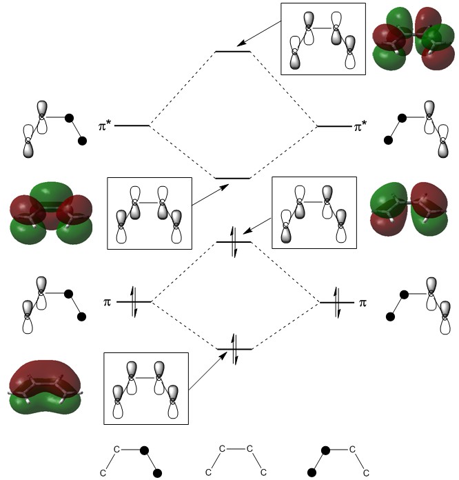
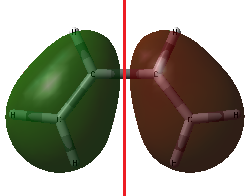
Typically, it is the HOMO and/or the LUMO that are most relevant for a molecule's reactivity, as they dictate its behaviour as an electron donor or acceptor, respectively. These two MOs are shown from a 'top-down' view below.
| cis-butadiene MOs | |
|---|---|
|

|
| HOMO of cis-butadiene | LUMO of cis-butadiene |
The HOMO is antisymmetric about the plane of symmetry of the molecule (drawn in red). It has one node, which is on this plane of symmetry. The LUMO, meanwhile, is symmetric about this plane of symmetry (red) and has two nodes (blue).
Ethylene
Next, the second reagent, ethylene, was considered. This is a very simple structure and so instead of starting off with a simple basis set, the an Opt+Freq calculation was run to the 6-31G(d) level straight away. The main goal was to visualise the molecule's MOs in order to then see their contributions to the reaction's transition state below.
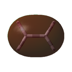
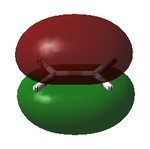
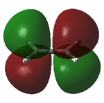
The optimised structure showed a C=C bond length of 1.33 Å and, as expected, had the D2h point group. The MOs are shown below:
| Ethylene MOs | |
|---|---|
|
|
| HOMO of ethylene | LUMO of ethylene |
Unlike cis-butadiene, where the HOMO was antisymmetric but the LUMO symmetric about the central C-C bond, this HOMO is symmetric while the LUMO is antisymmetric. This is already a good indicator that the molecules are likely to react with each other; the HOMO of one and the LUMO of the other are of the same symmetry and thus able to interact readily.
Transition state
The next goal was to find the structure of the transition state of the Diels-Alder cycloaddition of the cis-butadiene and ethylene structures optimised above.
In the first attempt, a guess for the transition state was drawn by placing a bicyclo[2.2.2]octane fragment from GaussView's library, deleting the two briding carbons, changing the valency of one end of the ring to match the starting material and product, and move the 'ethylene' group away by a distance of 2.0 Å for an initial guess. The 'Clean' functionality was then applied. The structure was optimised by the TS(Berny) method using the AM1 semi-empirical method.
This reaction did not converge. Examining the output file showed that the molecules seemed to be moving apart from each other, as shown below.
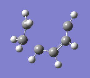
|
| Diverging structure of cis-butadiene/ethylene DA reaction |
Another guess was constructed with a separation of 2.5 Å in case this was closer to the transition state, but this was equally unsuccessful.
As a final attempt using the TS(Berny) method, the B3LYP/3-21G method was utilised, as this previously provided more accurate results. Again, however, the calculation did not converge. This time the output file showed a structure deviating significantly from the desired one, involving a cyclopropyl group, as below.

|
| Cyclopropyl-containing output of crashed calculation |
The decision was made that the TS(Berny) method was unsuitable for this goal as the simple guess seemed insufficient in locating the transition state. Instead, the reaction was set up for the QST3 method, which takes input in the form of the reactants, the products, and a guess for the transition state.
First, the product of the reaction, cyclohexene, was optimised using the same set of steps as previously used for cis-butadiene (AM1, then B3LYP/6-31G(d)). This gave the following structure:
| Cyclohexene (B3LYP/6-31G(d)) |
|---|
 |
| Optimised cyclohexene product structure |
This optimised structure was copied into the relevant product molecule group. In the reactant molecule group, the optimised cis-butadiene structure was copied, and an ethylene molecule was drawn with its plane parallel to that of the cis-butadiene molecule, but translated further away from this structure. Finally, the guess transition state was also built from cis-butadiene and an ethylene molecule, but with a close distance between the ethylene and the terminal cis-butadiene carbon atoms (2.0 Å). The numbering of the atoms was consistent between the molecule groups. The input was thus as shown here.
This calculation was successful in the first attempt, giving the following transition state structure.
| cis-butdiene/ethylene DA (AM1) |
|---|
 |
| Optimised transition state |
As indicated on the Jmol applet above, the separation of the terminal carbon atoms in this structure is 2.21 Å. Carbon atoms have a covalent radius of 0.76 Å[6] for single bonds, indicating that the typical length of a C-C single bond should be 1.52 Å. This is significantly longer, indicating that the interaction cannot be classes as a bond. However, the van der Waals' radius of carbon atoms is 1.70 Å[7]. Because the separation is significantly shorter than twice this distance (3.40 Å), there is a degree of interaction between the groups. From this it can be concluded that, as expected, the transition state represents a point along the reaction coordinate where the bond has begun to form but not yet completely formed.
The literature suggests a value of 2.27 Å[8], which lies within 3% of the value calculated here. This extent of agreement is encouraging, particularly given the relative simplicity of the computational method used.
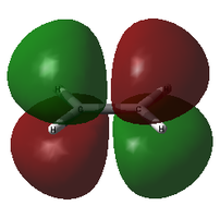
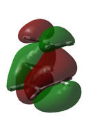
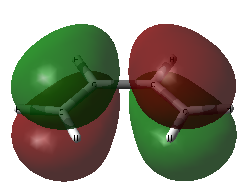
The structure was then optimised to the B3LYP/6-31G(d) level to facilitate comparison to the reactant molecules optimised to the same level. Due to a bug in the software, the checkpoint file could not be opened. The .log file could be, but this does not contain the MO surfaces. The problem persisted after running the calculation on HPC in order to get a .fchk file. In an attempt to deal with this issue, the Edit MOs window was accessed from the .log file, and then under the 'New MOs' tabs surfaces were generated using a 6-31G(d) basis set. This essentially took the geometry as input and calculated new approximate MOs. Because these are just approximate, there is a chance that the energies and shapes differ somewhat from those found in the actual Opt+Freq calculation. The HOMO and HOMO-1 energies of the MOs seemed to be quite close (-0.36407 and -0.36550 a.u., respectively) and so there was a risk that these HOMOs were reordered. Just in case, both were thus visualised, and the decision on which was the 'true' HOMO made by visually comparing them to the HOMO of the diene and the LUMO of the dienophile. It is these two MOs that contribute to the reaction because they are close in energy and of the same symmetry. They need to be of the same symmetry for the reaction to be allowed as this is a necessary condition for orbital mixing; the electrons can then transfer.
For this visual comparison, both candidates for the HOMO are shown below, alongside the ethylene LUMO and the cis-butadiene HOMO.
| Transition State MOs and their components | |||
|---|---|---|---|
 |
 |
 |
|
| Ethylene LUMO | TS HOMO-1 | TS HOMO | cis-butadiene HOMO |
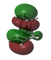
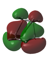
It seems that the order is correct; the approximated HOMO matches the combination of the ethylene LUMO and the cis-butadiene HOMO, but the HOMO-1 does not. Just to check, the transition state HOMO and HOMO-1 were also taken from the initial AM1 calculation. The comparison is shown below:
| HOMO Comparison | ||
|---|---|---|
 |
 |
|
| B3LYP/6-31G(d) HOMO (approx.) | AM1 HOMO | AM1 HOMO-1 |
It seems that the ordering was wrong not in the approximated 6-31G(d) case, but in the initial AM1 calculation; it is the HOMO-1 that matches the LCAO prediction, not the HOMO.
The LCAO-predicted HOMO is constructed of two antisymmetric orbitals (the ethylene LUMO and the cis-butadiene HOMO), giving an orbital antisymmetric across the plane of symmetry that goes through the transition state.
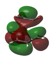
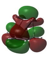
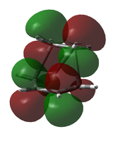
Due to this uncertainty, the possible LUMO orbitals were examined also. From an LCAO standpoint, the LUMO would be expected to be the out-of-phase combination of the two involved molecular orbitals (ethylene LUMO and cis-butadiene HOMO). The table below shows the LUMO and LUMO+1 candidates for both calculations.
| LUMO Comparison | |||
|---|---|---|---|
 |
 |
 |
|
| B3LYP/6-31G(d) LUMO (approx.) | B3LYP/6-31G(d) LUMO+1 (approx.) | AM1 LUMO | AM1 LUMO+1 |
It is apparent that, in both cases, it is not the LUMO but the LUMO+1 that matches the LCAO prediction.
While the LUMO predicted by LCAO theory is antisymmetric across the plane, the calculated LUMO is symmetric.
This leads to an interesting point that must be kept in mind when performing computational chemistry calculations. The above disagreement between LCAO prediction and calculated results can be explained in two ways. Either the simple LCAO prediction is wrong, and those predicted HOMOs and LUMOs do not actually match reality because the approach is overly simplified (as it does not consider the other orbitals present in the system). The other possibility is that the LCAO approach does match reality, but the computations don't. In the HOMO case, there was a disagreement between the two different computational methods chosen; this makes it clear that there is a strong dependence on the choice of method and basis set for computations and so it is difficult to tell what is the 'right' answer. The structures are not necessarily the most ideal, they are simply ideal within that method. It is difficult to prove that a computational result is the 'true' answer.
Confirmation of Transition State
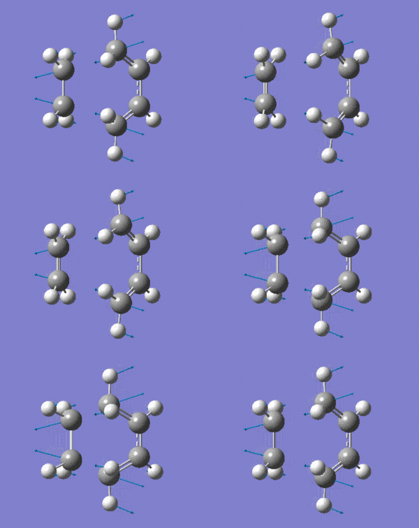
The optimised transition state has one vibrational mode with an imaginary frequency. Using the B3LYP/6-31G(d) calculation, the magnitude of this frequency is 525cm-1. The vibrational mode is shown below:
| Prototype DA TS Imaginary Vibration |
|---|
|
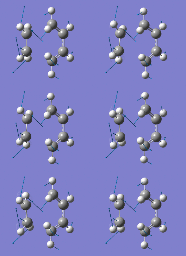
The vibrational mode matches the symmetric approach of the carbon termini while the C-C bonds are being broken/formed. The very symmetrical form of the vibration suggests synchronous bond formation.
Examining the lowest positive frequency vibrational mode at 135cm-1 reveals asynchronous bond formation character. Realistically, the molecules' reaction would be a combination of these two components.
| Prototype DA TS Lowest Positive Vibration |
|---|
|
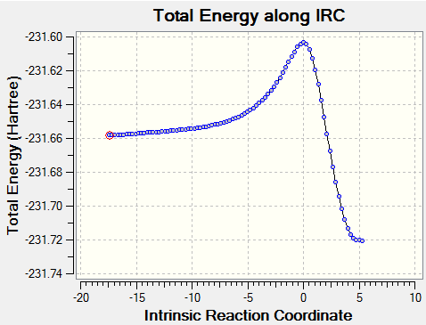
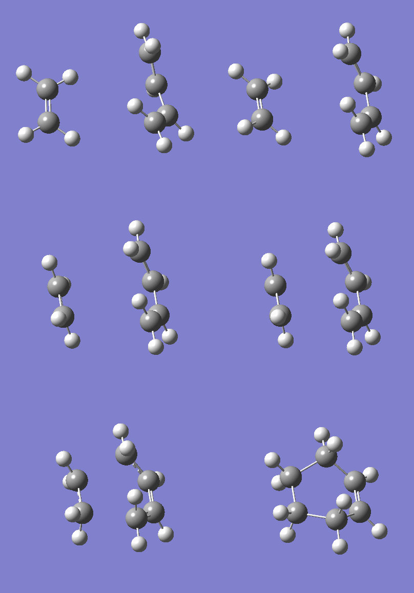
For further confirmation, an IRC calculation was run in both directions in order to visualise the progression from reactants to products. N, the maximum number of steps, was set to 150, and the force constants were set to be calculated for each step. Below is the energy plot along the reaction coordinate, as well as an animation of the steps. The total number of steps is 87, lower than the maximum set, indicating that the minima of the reactants and products were found comfortably within the constraints.
| Prototype DA IRC | |
|---|---|
|
|
As expected, the products are lower in energy than the reactants. The reaction passes through the calculated transition state in a concerted manner as expected for a pericyclic reaction. The animation shows the molecules aligning to each other, with the cis-butadiene becoming planar (s-cis), before the bond formation occurs.
Maleic Anhydride + cyclohexa-1,3-diene
The next aim was to calculate a more realistic example of a Diels Alder reaction. The reagents are maleic anhydride, as a very electron deficient dienophile, and cyclohexa-1,3-diene, which is comparatively electron rich and, more importantly, locked into the s-cis conformation. The fact that the dienophile is electron deficient lowers the energy of its LUMO, aiding reactivity because, as shown above, it is the dienophile's LUMO that reacts in a typical Diels Alder reaction. Similarly the diene's electron rich HOMO is slightly elevated in energy and thus the electrons are more likely to transfer to the dienophile's HOMO. The conformational lock makes it far more likely that two colliding molecules will have their orbitals in an arrangement facilitating reaction.
Maleic Anhydride
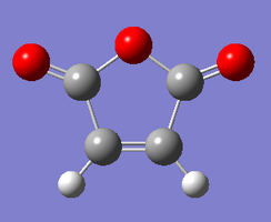
The first reagent, maleic anhyrdide, was first optimised using the semi-empirical AM1 method. The B3LYP/6-31G(d) method was then chosen for further optimisation. This DFT method uses polarised basis orbitals, and so can be expected to yield more realistic MO surfaces. The optimised structure is as shown:
| Maleic Anhydride (B3LYP/6-31G(d)) |
|---|
 |
| Optimised structure |
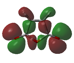
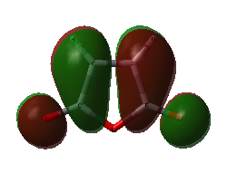
A frequency calculation was run in order to find the MO surfaces. The HOMO and the LUMO are shown below.
| Maleic Anhydride | |
|---|---|
|
|
| HOMO of maleic anhydride | LUMO of maleic anhydride |
Cyclohexa-1,3-diene
The same procedure was performed on the other reactant, cyclohexa-1,3-diene. The structure optimised to B3LYP/6-31G(d) is below:
| Cyclohexa-1,3-diene (B3LYP/6-31G(d)) |
|---|
 |
| Optimised structure |
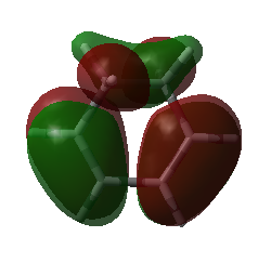
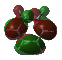
Again, a frequency calculation was performed using the same B3LYP/6-31G(d) method in order to visualise the MOs. The HOMO and LUMO are shown below.
| Cyclohexa-1,3-diene | |
|---|---|
|
|
| HOMO of cyclohexa-1,3-diene | LUMO of cyclohexa-1,3-diene |
Transition State Method
Locating the transition states for this reaction proved to be quite a challenge. With many attempts, the calculation diverged and crashed, and examination of the produced output files showed that the reactant molecules were 'flying apart' instead of coming together to form a transition structure. The picture below shows a representative example of such an output file:
| Representative Crashed Output (Diverged) |
|---|

|
The initial attempt was made using the method most simple to set up - a direct optimisation to a TS(Berny). This was attempted first with the AM1 method, then HF/3-21G and B3LYP/6-31G. None of the runs were successful, despite attempting a range of starting geometries (varying the separations between carbon termini, and the orientation between the molecules, being either parallel, at an angle, or twisted in such a way that the six-membered ring around which the electrons were expected to flow during the pericyclic step was planar).
In search for a more robust method, the QST3 method was chosen. For this, the expected product was first optimised separately and then pasted into a set of three molecule groups alongside the reactants and a guess for the transition state. The numbering was set to be consistent. Even with this method, the reactants flew apart. A representative input file can be seen here. The same issue also occurred when attempting a QST2 calculation, and using both the AM1 and HF/3-21G methods.
Finally, the frozen coordinate method was attempted. For this, a guess transition state was corrected by placing the two molecules parallel to each other, with the carbon termini frozen at equal distances. At first the guess separation was set to 2.6 Å, which again caused a diverged run. Another guess was then set to 2.27 Å, which is the literature value for the prototype reaction[8]. This finally resulted in a successful calculation using the HF/3-21G method. The same method worked for both the endo and exo geometries.
Both geometries were then optimised further to the B3LYP/6-31G(d) method, and frequency calculations were performed to find the MOs. Once again the bug appeared where the .chk output could not be opened. However, re-running the calculations on HPC and thus obtaining a .fchk output solved the issue.
Exo Transition State
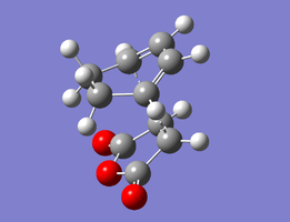
The structures optimised to HF/3-21G and that to B3LYP/6-31G(d) are below. Relevant bond lengths are embedded in the Jmol applet.
| Exo Transition State | |
|---|---|
 |
 |
| HF/3-21G | B3LYP/6-31G(d) |
In this structure, which has been shown experimentally to be less stable[9], the maleic anhydride (O=C)-O-(C=O) bridge points towards the H2C−CH2 bridge of the cyclohexene ring. The separation between the carboxyl oxygen and the closest alkyl bridge hydrogen atoms is 2.69 Å.
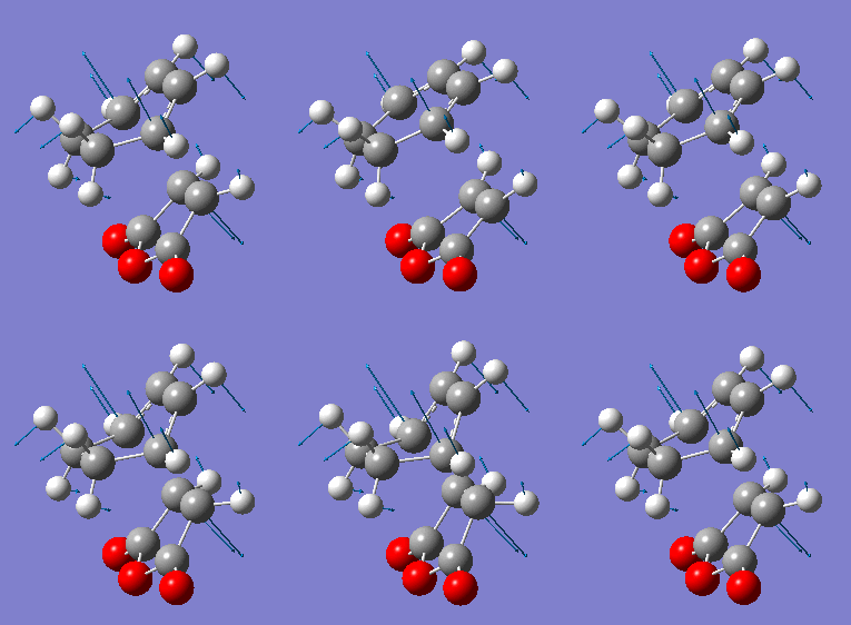
As before, to confirm the transition state, the imaginary frequency vibrational mode was examined, an an IRC calculation was run.
The imaginary frequency has a magnitude of 448cm-1. It shows synchronous bond formation between the two reactants.
| Exo Imaginary Frequency |
|---|
|
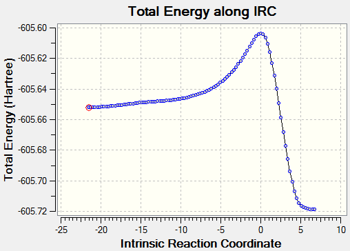
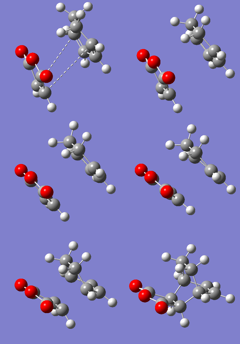
To confirm the transition state, an IRC was run in both directions. It was set to calculate the force constants in each step for a maximum of 150 steps. 102 steps were taken by the program, indicating it reached the necessary minima on both sides.
| Exo IRC | |
|---|---|
|
|
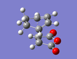
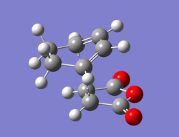
Endo Transition State
The structures optimised to HF/3-21G and that to B3LYP/6-31G(d) are below. Relevant bond lengths and are embedded in the Jmol applet.
| Endo Transition State | |
|---|---|
 |
 |
| HF/3-21G | B3LYP/6-31G(d) |
In this structure, the maleic anhydride (O=C)-O-(C=O) bridge points towards the HC=CH bridge of the cyclohexene ring. The separation between the carboxyl oxygen and the closest alkyl bridge hydrogen atoms is 3.22 Å. This is shorter than in the exo case because the alkyl group has sp2 rather than sp3 carbons, so the hydrogens are able to move further away from the carboxyl groups in space. This lack of steric strain likely contributes to the increased stability of the endo transition state, making the endo product kinetically favourable.
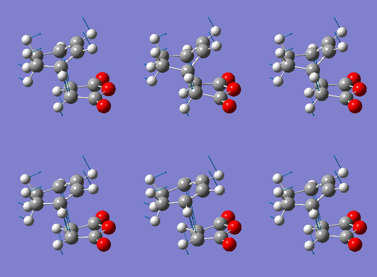
The imaginary frequency has a magnitude of 447cm-1. Like the exo case, it shows synchronous bond formation.
| Endo Imaginary Frequency |
|---|
|
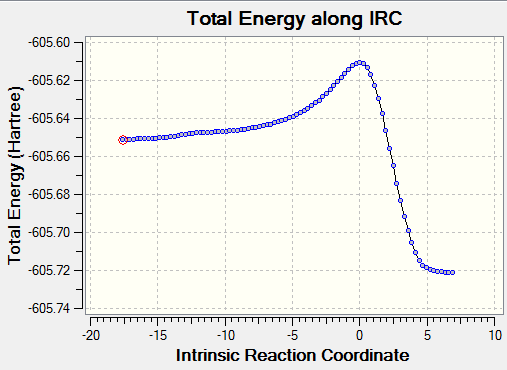
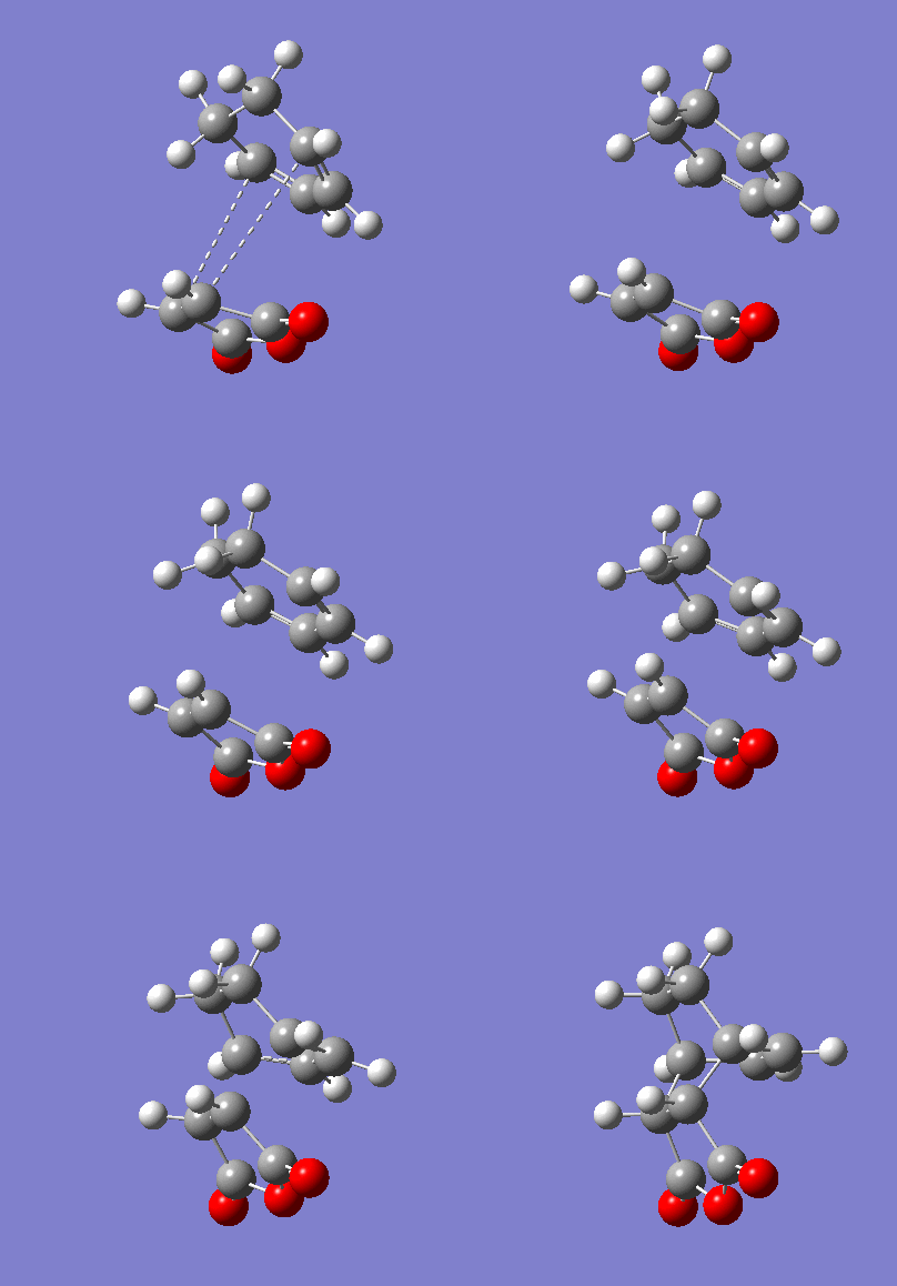
To confirm the transition state, an IRC was run. 90 of the set maximum of 150 steps were taken before minima were found on both sides of the transition state.
| Endo IRC | |
|---|---|
|
|
Analysis
In agreement with experimental observation, the exo transition state was found to be less stable than the endo transition state. As mentioned above, this can be attributed at least in part due to the increased steric strain from contacts between the carboxyl-containing bridge on maleic anhydride and the alkyl bridge on the cyclohexene ring.
The calculated sum of the electronic and thermal free energies of the exo transition state is -612.534261 Hartrees, while that of the endo transition state is -612.538328 Hartrees. This indicates that the endo TS is more stable by a difference of 0.004067 Hartrees or 2.55 kcal/mol.
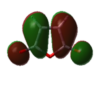
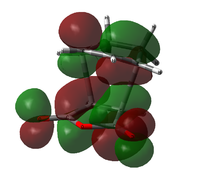
While some of this energy difference can be attributed to the strain discussed above, there may also be a component related to the molecular orbital interactions. The table below shows the HOMO and LUMO of the reactants and both transition states, calculated to the B3LYP/6-31G(d) level.
| Structure | HOMO | LUMO |
|---|---|---|
| Maleic Anhydride | 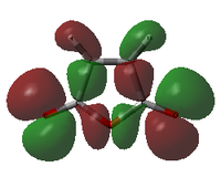 |
|
| Cyclohexa-1,3-diene |  |

|
| Endo TS | 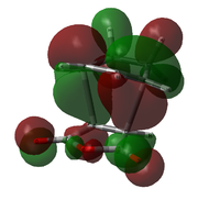 |
|
| Exo TS | 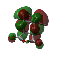 |
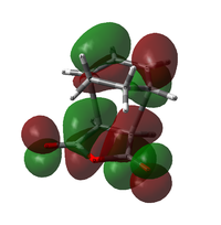
|
Both transitions appear to be combinations of the LUMO of maleic anhydride and the HOMO of the diene, as expected. The key difference lies in the orientation of the maleic anhydride group; in the endo transition state, it lies underneath the pi system of the forming double bond, while in the exo case, it points away from this system. This results in a far less cohesive appearance of the HOMO in the exo case. In the Endo case, the lobes on the pi system look almost distorted, being pulled down towards the maleic anhydride group. It is mixing with the upper lobes of the maleic anhydride ring.
This is the secondary orbital effect, a phenomenon characterised by a positive overlap between frontier molecular orbitals of a pericyclic reaction in regions other than that directly associated with bond formation. It stabilises the endo transition state through favourable orbital interactions. However, for reactions such as these, it has been found to not be the key deciding factor, in fact, research suggests that the steric effect is at least as important, if not more so[10].
Conclusions and suggestions for further study
The two Diels Alder reactions calculated above revealed two key observations, one about computational chemistry, the other about Diels Alder reactions:
- When performing any kind of computation, it is important to not simply take the output at face value. As shown by the MO analysis of the transition state of the prototype reaction, simple changes in method and/or basis set can cause reordering of MOs and affect their shapes. The limitations of each method must always be kept in mind. (The AM1 method, for example, is optimised towards reliably calculating structures' energies, while the DFT method focuses more on orbital effects and was thus chosen for all MO representations above.)
- While the secondary orbital effect can be observed in Diels Alder reactions containing substituents such as the one between maleic anhydride and cyclohexa-1,3-diene studied above, it is not the only factor contributing towards the stability of the relevant transition states. Others, such as steric effects, also come into play and must be taken into considerations. In this particular case, both steric and orbital effects favour the same transition state, but in other systems they may be in conflict, making their relative magnitudes very relevant.
None of the above calculations incorporated any solvent effects, as they were optimised in the absence of a solvation model. For further comparison to experiments, and to study these solvent effects, it would be interesting to attempt the same calculations in a range of solvents (a comparison could be drawn, for example, between a non-coordinating solvent such as hexane, and one capable of forming hydrogen bonds to the maleic anhydride reactant).
It could also be interesting to further study the extent of secondary orbital effects in Diels Alder reactions by devising a system where the steric effect favours one transition state while the orbital effects favour another. These transition states' relative energies would then indicate which of the two effects is dominant for that system.
Additionally, all systems studied above are symmetric across a plane, resulting in perfectly symmetric or antisymmetric MOs. It would be interesting to see how asymmetric substituents affect the reactivity. Perhaps this would result in more asynchronous bond formation. If the bonds are shown to be formed sequentially rather than concertedly, this would mean that the reactions cannot be considered purely pericyclic (as pericyclic reactions are characterised by concerted bond formation/breakage). Ionic contributions to the reactivity would then be relevant.
Calculation Log
Initial Cope Reactant Optimisations
HF 3-21G
Anti 1,5-hexadiene
.log file here
| Anti Hexadiene Optimisation | |
|---|---|
| File Name | AMS_ANTI_HF321G |
| File Type | .log |
| Calculation Type | FOPT |
| Calculation Method | RHF |
| Basis Set | 3-21G |
| Charge | 0 |
| Spin | Singlet |
| E(RHF) | -231.69260235 a.u. |
| RMS Gradient Norm | 0.00001824 a.u. |
| Imaginary Freq | |
| Dipole Moment | 0.2021 Debye |
| Point Group | C2 |
| Job cpu time: 0 days 0 hours 1 minutes 19.0 seconds. | |
         Item               Value     Threshold  Converged?
 Maximum Force            0.000056     0.000450     YES
 RMS     Force            0.000010     0.000300     YES
 Maximum Displacement     0.001547     0.001800     YES
 RMS     Displacement     0.000459     0.001200     YES
 Predicted change in Energy=-2.090890D-08
 Optimization completed.
Gauche 1,5-hexadiene
.log file here
| Gauche Hexadiene Optimisation | |
|---|---|
| File Name | AMS_GAUCHE_HF321G |
| File Type | .log |
| Calculation Type | FOPT |
| Calculation Method | RHF |
| Basis Set | 3-21G |
| Charge | 0 |
| Spin | Singlet |
| E(RHF) | -231.69166701 a.u. |
| RMS Gradient Norm | 0.00001086 a.u. |
| Imaginary Freq | |
| Dipole Moment | 0.3805 Debye |
| Point Group | C2 |
| Job cpu time: 0 days 0 hours 1 minutes 20.0 seconds. | |
         Item               Value     Threshold  Converged?
 Maximum Force            0.000018     0.000450     YES
 RMS     Force            0.000006     0.000300     YES
 Maximum Displacement     0.001011     0.001800     YES
 RMS     Displacement     0.000331     0.001200     YES
 Predicted change in Energy=-1.009947D-08
 Optimization completed.
Gauche-opp 1,5-hexadiene
.log file here
| Gauche-Opp Hexadiene Optimisation | |
|---|---|
| File Name | AMS_GAUCHEOPP_HF321G |
| File Type | .log |
| Calculation Type | FOPT |
| Calculation Method | RHF |
| Basis Set | 3-21G |
| Charge | 0 |
| Spin | Singlet |
| E(RHF) | -231.69153035 a.u. |
| RMS Gradient Norm | 0.00000514 a.u. |
| Imaginary Freq | |
| Dipole Moment | 0.1281 Debye |
| Point Group | C1 |
| Job cpu time: 0 days 0 hours 1 minutes 25.0 seconds. | |
         Item               Value     Threshold  Converged?
 Maximum Force            0.000017     0.000450     YES
 RMS     Force            0.000003     0.000300     YES
 Maximum Displacement     0.001218     0.001800     YES
 RMS     Displacement     0.000325     0.001200     YES
 Predicted change in Energy=-2.248480D-09
 Optimization completed.
Anti-opp 1,5-hexadiene
.log file here
| Antiopp Hexadiene Optimisation | |
|---|---|
| File Name | AMS_ANTIOPP_HF321G |
| File Type | .log |
| Calculation Type | FOPT |
| Calculation Method | RHF |
| Basis Set | 3-21G |
| Charge | 0 |
| Spin | Singlet |
| E(RHF) | -231.69253516 a.u. |
| RMS Gradient Norm | 0.00004313 a.u. |
| Imaginary Freq | |
| Dipole Moment | 0.0000 Debye |
| Point Group | CI |
| Job cpu time: 0 days 0 hours 1 minutes 16.0 seconds. | |
         Item               Value     Threshold  Converged?
 Maximum Force            0.000110     0.000450     YES
 RMS     Force            0.000022     0.000300     YES
 Maximum Displacement     0.000557     0.001800     YES
 RMS     Displacement     0.000235     0.001200     YES
 Predicted change in Energy=-1.326925D-07
 Optimization completed.
Gauche-face 1,5-hexadiene
.log file here
| Gauche-Face Hexadiene Optimisation | |
|---|---|
| File Name | AMS_GAUCHEFACE_HF321G |
| File Type | .log |
| Calculation Type | FOPT |
| Calculation Method | RHF |
| Basis Set | 3-21G |
| Charge | 0 |
| Spin | Singlet |
| E(RHF) | -231.69266121 a.u. |
| RMS Gradient Norm | 0.00001408 a.u. |
| Imaginary Freq | |
| Dipole Moment | 0.3406 Debye |
| Point Group | C1 |
| Job cpu time: 0 days 0 hours 2 minutes 21.0 seconds. | |
         Item               Value     Threshold  Converged?
 Maximum Force            0.000043     0.000450     YES
 RMS     Force            0.000007     0.000300     YES
 Maximum Displacement     0.000936     0.001800     YES
 RMS     Displacement     0.000228     0.001200     YES
 Predicted change in Energy=-1.585783D-08
 Optimization completed.
B3LYP 6-31G(d)
Anti2 1,5-hexadiene Optimisation
.log file here
| Anti2 Hexadiene ReOptimisation | |
|---|---|
| File Name | AMS_ANTI2_631GD |
| File Type | .log |
| Calculation Type | FOPT |
| Calculation Method | RB3LYP |
| Basis Set | 6-31G(d) |
| Charge | 0 |
| Spin | Singlet |
| E(RB3LYP) | -234.61170686 a.u. |
| RMS Gradient Norm | 0.00001212 a.u. |
| Imaginary Freq | |
| Dipole Moment | 0.0000 Debye |
| Point Group | CI |
| Job cpu time: 0 days 0 hours 6 minutes 23.0 seconds. | |
         Item               Value     Threshold  Converged?
 Maximum Force            0.000014     0.000450     YES
 RMS     Force            0.000006     0.000300     YES
 Maximum Displacement     0.000179     0.001800     YES
 RMS     Displacement     0.000079     0.001200     YES
 Predicted change in Energy=-1.379966D-08
 Optimization completed.
Frequency Analysis
.log file here
| Anti2 Hexadiene Frequency | |
|---|---|
| File Name | AMS_ANTI2_631GD_FREQ |
| File Type | .log |
| Calculation Type | FREQ |
| Calculation Method | RB3LYP |
| Basis Set | 6-31G(d) |
| Charge | 0 |
| Spin | Singlet |
| E(RB3LYP) | -234.61170686 a.u. |
| RMS Gradient Norm | 0.00001213 a.u. |
| Imaginary Freq | 0 |
| Dipole Moment | 0.0000 Debye |
| Point Group | CI |
| Job cpu time: 0 days 0 hours 2 minutes 44.0 seconds. | |
 Low frequencies ---  -23.2792   -6.7528    0.0005    0.0007    0.0012    2.7446
 Low frequencies ---   72.6092   79.0575  121.6502
Cope Transition States
Allyl Building Block
.log file here
| Allyl Optimisation | |
|---|---|
| File Name | AMS_ALLYL_HF321G |
| File Type | .log |
| Calculation Type | FOPT |
| Calculation Method | UHF |
| Basis Set | 3-21G |
| Charge | 0 |
| Spin | Doublet |
| E(UHF) | -115.82304011 a.u. |
| RMS Gradient Norm | 0.00000156 a.u. |
| Imaginary Freq | |
| Dipole Moment | 0.0292 Debye |
| Point Group | C1 |
| Job cpu time: 0 days 0 hours 5 minutes 47.0 seconds. | |
         Item               Value     Threshold  Converged?
 Maximum Force            0.000004     0.000450     YES
 RMS     Force            0.000001     0.000300     YES
 Maximum Displacement     0.000027     0.001800     YES
 RMS     Displacement     0.000011     0.001200     YES
 Predicted change in Energy=-9.542899D-11
 Optimization completed.
Chair Structure
Hessian Method
.log file here
| Title Card Required | |
|---|---|
| File Name | AMS_TS_CHAIR_HF321G |
| File Type | .log |
| Calculation Type | FREQ |
| Calculation Method | RHF |
| Basis Set | 3-21G |
| Charge | 0 |
| Spin | Singlet |
| E(RHF) | -231.61932231 a.u. |
| RMS Gradient Norm | 0.00002893 a.u. |
| Imaginary Freq | 1 |
| Dipole Moment | 0.0011 a.u. |
| Point Group | C1 |
| Job cpu time: 0 days 0 hours 0 minutes 51.0 seconds. | |
         Item               Value     Threshold  Converged?
 Maximum Force            0.000072     0.000450     YES
 RMS     Force            0.000017     0.000300     YES
 Maximum Displacement     0.001367     0.001800     YES
 RMS     Displacement     0.000285     0.001200     YES
 Predicted change in Energy=-1.579785D-07
 Optimization completed.
Frozen Coordinate Method
Step 1:
.log file here
| Chair TS FrozCoord1 | |
|---|---|
| File Name | AMS_TS_CHAIR_HF321G_FROZCOORD1 |
| File Type | .log |
| Calculation Type | FOPT |
| Calculation Method | RHF |
| Basis Set | 3-21G |
| Charge | 0 |
| Spin | Singlet |
| E(RHF) | -231.61562313 a.u. |
| RMS Gradient Norm | 0.00317887 a.u. |
| Imaginary Freq | |
| Dipole Moment | 0.0027 Debye |
| Point Group | C1 |
| Job cpu time: 0 days 0 hours 5 minutes 24.0 seconds. | |
         Item               Value     Threshold  Converged?
 Maximum Force            0.000017     0.000450     YES
 RMS     Force            0.000005     0.000300     YES
 Maximum Displacement     0.000521     0.001800     YES
 RMS     Displacement     0.000181     0.001200     YES
 Predicted change in Energy=-1.163432D-08
 Optimization completed.
Step 2:
.log file here
| Chair TS FrozCoord2 | |
|---|---|
| File Name | AMS_TS_CHAIR_HF321G_FROZCOORD2 |
| File Type | .log |
| Calculation Type | FTS |
| Calculation Method | RHF |
| Basis Set | 3-21G |
| Charge | 0 |
| Spin | Singlet |
| E(RHF) | -231.61932248 a.u. |
| RMS Gradient Norm | 0.00000231 a.u. |
| Imaginary Freq | |
| Dipole Moment | 0.0000 Debye |
| Point Group | C1 |
| Job cpu time: 0 days 0 hours 9 minutes 30.0 seconds. | |
         Item               Value     Threshold  Converged?
 Maximum Force            0.000004     0.000450     YES
 RMS     Force            0.000001     0.000300     YES
 Maximum Displacement     0.360621     0.001800     NO
 RMS     Displacement     0.093539     0.001200     NO
 Predicted change in Energy=-1.499934D-09
 Optimization completed on the basis of negligible forces.
6-31G(d)
Reoptimisation:
.log file here
| Chair TS ReOpt | |
|---|---|
| File Name | AMS_TS_CHAIR_631GD |
| File Type | .log |
| Calculation Type | FTS |
| Calculation Method | RB3LYP |
| Basis Set | 6-31G(d) |
| Charge | 0 |
| Spin | Singlet |
| E(RB3LYP) | -234.55698303 a.u. |
| RMS Gradient Norm | 0.00001194 a.u. |
| Imaginary Freq | |
| Dipole Moment | 0.0000 Debye |
| Point Group | C1 |
| Job cpu time: 0 days 0 hours 5 minutes 48.0 seconds. | |
         Item               Value     Threshold  Converged?
 Maximum Force            0.000022     0.000450     YES
 RMS     Force            0.000005     0.000300     YES
 Maximum Displacement     0.000077     0.001800     YES
 RMS     Displacement     0.000025     0.001200     YES
 Predicted change in Energy=-3.411793D-09
 Optimization completed.
Frequency Analysis:
.log file here
| Chair TS ReOpt Freq | |
|---|---|
| File Name | AMS_TS_CHAIR_631GD_FREQ |
| File Type | .log |
| Calculation Type | FREQ |
| Calculation Method | RB3LYP |
| Basis Set | 6-31G(d) |
| Charge | 0 |
| Spin | Singlet |
| E(RB3LYP) | -234.55698303 a.u. |
| RMS Gradient Norm | 0.00001192 a.u. |
| Imaginary Freq | 1 |
| Dipole Moment | 0.0000 Debye |
| Point Group | C1 |
| Job cpu time: 0 days 0 hours 3 minutes 32.0 seconds. | |
 Low frequencies --- -565.5415   -0.0005   -0.0005    0.0006   21.9513   27.2883
 Low frequencies ---   39.7425  194.5212  267.9557
At 0.01K, .out file here.
Boat Structure
QST2 Method
First (Failed) Try:
.log file here
| File Name | AMS_TS_BOAT_HF321G_QST2 |
| File Type | .log |
| Calculation Type | FOPT |
| Calculation Method | |
| Basis Set | |
| Charge | 0 |
| Spin | Singlet |
| E(RHF) | -231.61932118 a.u. |
| RMS Gradient Norm | 0.00006362 a.u. |
| Imaginary Freq | |
| Dipole Moment | 0.0000 Debye |
| Point Group | C2H |
Second (Successful) Try:
.log file here
| Title Card Required | |
|---|---|
| File Name | AMS_TS_BOAT_HF321G_QST2_RETRY |
| File Type | .log |
| Calculation Type | FREQ |
| Calculation Method | RHF |
| Basis Set | 3-21G |
| Charge | 0 |
| Spin | Singlet |
| E(RHF) | -231.60280229 a.u. |
| RMS Gradient Norm | 0.00003304 a.u. |
| Imaginary Freq | 1 |
| Dipole Moment | 0.1582 Debye |
| Point Group | C1 |
| Job cpu time: 0 days 0 hours 0 minutes 29.0 seconds. | |
         Item               Value     Threshold  Converged?
 Maximum Force            0.000081     0.000450     YES
 RMS     Force            0.000021     0.000300     YES
 Maximum Displacement     0.001645     0.001800     YES
 RMS     Displacement     0.000498     0.001200     YES
 Predicted change in Energy=-1.093943D-07
 Optimization completed.
6-31G(d)
Reoptimisation:
.log file here
| Boat TS ReOpt | |
|---|---|
| File Name | AMS_TS_BOAT_631GD |
| File Type | .log |
| Calculation Type | FTS |
| Calculation Method | RB3LYP |
| Basis Set | 6-31G(d) |
| Charge | 0 |
| Spin | Singlet |
| E(RB3LYP) | -234.54309307 a.u. |
| RMS Gradient Norm | 0.00000446 a.u. |
| Imaginary Freq | |
| Dipole Moment | 0.0613 Debye |
| Point Group | C1 |
| Job cpu time: 0 days 0 hours 4 minutes 53.0 seconds. | |
         Item               Value     Threshold  Converged?
 Maximum Force            0.000009     0.000450     YES
 RMS     Force            0.000003     0.000300     YES
 Maximum Displacement     0.000172     0.001800     YES
 RMS     Displacement     0.000054     0.001200     YES
 Predicted change in Energy=-3.425817D-09
 Optimization completed.
Frequency Analysis:
.log file here
| Boat TS ReOpt Freq | |
|---|---|
| File Name | AMS_TS_BOAT_631GD_FREQ |
| File Type | .log |
| Calculation Type | FREQ |
| Calculation Method | RB3LYP |
| Basis Set | 6-31G(d) |
| Charge | 0 |
| Spin | Singlet |
| E(RB3LYP) | -234.54309307 a.u. |
| RMS Gradient Norm | 0.00000446 a.u. |
| Imaginary Freq | 1 |
| Dipole Moment | 0.0613 a.u. |
| Point Group | C1 |
| Job cpu time: 0 days 0 hours 3 minutes 33.0 seconds. | |
 Low frequencies --- -530.3738   -8.3303   -0.0009   -0.0009   -0.0009   15.4636
 Low frequencies ---   17.6089  135.6170  261.7076
IRC
Initial Calculation (N=50)
.log file here
| File Name | AMS_TS_CHAIR_HF321G_IRC |
| File Type | .log |
| Calculation Type | IRC |
| Calculation Method | |
| Basis Set | |
| Charge | 0 |
| Spin | Singlet |
| E(RHF) | -231.69157916 a.u. |
| RMS Gradient Norm | 0.00015223 a.u. |
| Imaginary Freq | |
| Dipole Moment | 0.3631 Debye |
| Point Group | C2 |
| Job cpu time: 0 days 0 hours 15 minutes 20.0 seconds. | |
Minimisation from last step
.log file here
| IRC50 Final Step Minimisation | ||
|---|---|---|
| File Name | ams_ts_chair_hf321g_irc_lastmin | |
| File Type | .log | |
| Calculation Type | FOPT | |
| Calculation Method | RHF | |
| Basis Set | 3-21G | |
| Charge | 0 | |
| Spin | Singlet | |
| E(RHF) | -231.69166702 a.u. | |
| RMS Gradient Norm | 0.00000474 a.u. | |
| Imaginary Freq | ||
| Dipole Moment | 0.3806 Debye | |
| Point Group | C2 | |
| Job cpu time: 0 days 0 hours 1 minutes 23.0 seconds. | ||
         Item               Value     Threshold  Converged?
 Maximum Force            0.000010     0.000450     YES
 RMS     Force            0.000003     0.000300     YES
 Maximum Displacement     0.000299     0.001800     YES
 RMS     Displacement     0.000091     0.001200     YES
 Predicted change in Energy=-2.403455D-09
 Optimization completed.
Prototype Diels Alder Reaction
- cis-butadiene .log file
- ethylene .log file
- cyclohexene .log file
- QST3 transition state .log file
- TS reopt D-Space
- IRC .log file
Diels Alder Reaction
- endo TS location HF .log file
- exo TS location HF .log file
- endo B3LYP D-Space
- exo B3LYP D-Space
- endo IRC D-Space
- exo IRC D-Space
References
- ↑ A. C. Cope and E. M. Hardy, J. Am. Chem. Soc., 1940, 62, 441–444.Template:DOI10.1021/ja01859a055
- ↑ R. Hoffmann and R. B. Woodward, J. Am. Chem. Soc., 1965, 87, 2046–2048. DOI:10.1021/ja01087a034
- ↑ Lab Script Appendix 1
- ↑ Physical Computational Module Script: Optimising Chair and Boat Transition Structures
- ↑ Alkadienes and Polyunsaturated Hydrocarbons
- ↑ CRC Handbook of Chemistry and Physics, ed. W. M. Haynes, D. R. Lide and T. J. Bruno, CRC Press, Boca Raton, 93rd edn., 2012.
- ↑ A. Bondi, The Journal of Physical Chemistry, 1964, 68, 441–451. DOI:10.1021/j100785a001
- ↑ 8.0 8.1 1. K. Black, P. Liu, L. Xu, C. Doubleday, and K. N. Houk, Proc. Natl. Acad. Sci. U. S. A., 2012, 109, 12860–5. DOI:10.1073/pnas.1209316109
- ↑ 1. D. Craig, J. J. Shipman, and R. B. Fowler, J. Am. Chem. Soc., 1961, 83, 2885–2891. DOI:10.1021/ja01474a023
- ↑ M. A. Fox, R. Cardona, and N. J. Kiwiet, J. Org. Chem., 1987, 52, 1469–1474. DOI:10.1021/jo00384a016

