Rep:Mod:SXC13
Transition states and reactivity
In this experiment, the transition structures on potential surfaces for the Cope rearrangement and Diels-Alder cycloaddition reactions are generated. All simulations were done by using GaussView program.
The cope rearrangement of 1,5-hexadiene
The [3,3]-sigmatropic shift rearrangement has been studied by both experiments and computations for years. [1][2]The mechanism is now normally agreed to occur via a "chair" or a "boat" transition structure (Figure 1.). The "chair" conformation has been proven to be lower in energy. It is confirmed that the optimizations at the B3LYP/6-31G level of the theory give better result of energy comparing to those at HF/6-21G.

In this part, the favored reaction mechanism is determined by finding out the low-energy minima and transition structures on the 1,5-hexadiene potential energy surface.
The structure of 1,5-hexadiene with an "anti" linkage for the central four carbon atoms was optimized at the HF/3-21G level of the theory. As shown in Figure.2, the molecule has a symmetry of Ci and the energy of this structure is calculated to be -231.69253528 Ha. Therefore the result structure is determined to be anti2 by comparing this energy with the structures in Appendix 1.
1,5-hexadiene (Anti) |
The structure of 1,5-hexadiene with a "gauche" linkage for the central four carbon atoms was then optimized also at the HF/3-21G level of theory. The calculated energy of this structure is -231.69266120 Ha, which is slightly higher than the anti2 structure. Comparing with Appendix 1, the structure is equivalent to gauche3, for which the point group is C1.
1,5-hexadiene (Anti) |
The lowest energy conformation of a reactant is used as a reference in the calculations of lowest activation energies and enthalpies. In this case, gauche3 structure, shown in Figure. 3, is the lowest energy conformation, with zero relative energy.
The structure of anti2 was re-optimized at the B3LYP/3-21G level of theory. The energy is calculated to be -234.55970873 Ha, lower than that calculated in the previous optimization. This proofs that the simulation at B3LYP/6-31G gives lower energy than that at HF/3-21G.
1,5-hexadiene (Anti) |
The computed energies are shown in Table 1.
| Energy | Description | Relative Energy/Hartrees B3LYP/6-31G |
| Sum of electronic and zero-point Energies | Potential energy at 0 K including the zero-point vibrational energy (E = Eelec + ZPE) | -234.416224 |
| Sum of electronic and thermal Energies | Energy contributions from the translational, rotational, and vibrational energy modes (E = E + Evib + Erot + Etrans) at 298.15 K and 1 atm | -234.408935 |
| Sum of electronic and thermal Enthalpies | As above but contains an additional correction for RT (H = E + RT) | -234.407991 |
| Sum of electronic and thermal Free Energies | As above but includes entropic contribution to the free energy (G = H - TS) | -234.447830 |
Optimization of "Chair" and "Boat" structures
Computing the force constants at the start of the calculation, using the redundant coordinate editor and using the QST2 are the methods for optimizing the transition structure.
"Chair" conformation of cope rearrangement
In this part, to work out the "Chair" rearrangement, Hartree Fock and the default set 3-21G were used. Figure 5. shown below is the infrared spectrum simulated by the optimization to a Berny TS. The force constant was calculated once and the frequency calculation carried out spontaneously. The result for this simulation is summarized in Table 2..
| Energy | Bond Length | Energy/Hartrees | Frequency | Animation |
| "Chair" TS | 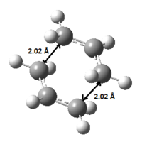 |
-231.61932242 | Imaginary frequency of -818.07 | 
|

The transition structure was then re-optimized by using the frozen coordinate method. The distance between the two terminal ends of the allyl fragments were frozen to 2.2 Å. This gives a similar structure as the HF/3-21G one (in Table 2.) and the computed energy is -231.61502682 Ha.
| Bond Length | Energy/Hartrees | |
| "Chair" TS | 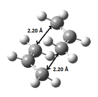 |
-231.61502682 |
The structure was then optimized again without the distance between the two fragment ends fixed. This time the energy is calculated to be -231.69166702 Ha and the bond lengths of the two ends are quite different, one 1.55 Å while the other 4.39 Å. Therefore the structure is not a "chair" shape, unlike the optimized structure gives by freezing the coordinates shown above.
| Bond Length | Energy/Hartrees | |
| "Chair" TS |  |
-231.69166702 |
"Boat" conformation of cope rearrangement
QST2, a different method, was used in this part to compute the "boat" rearrangement.
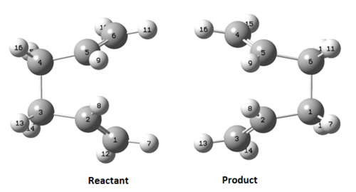
Firstly, the anti2 structure optimized above was used as a template. The two copies of anti2 gives the reactant and the product molecules. The molecules were re-numbered as Figure 6. shown below.
Then the optimization was carried out at HF/3-21G using QST2 method.
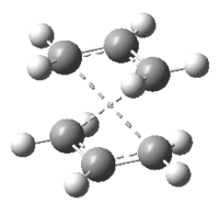
The first optimization failed, as shown in Figure 7. and 8, produced a C2h symmetry point group. The transition state is dissociated. This leads to an unsuccessful optimization. The frequency calculation gives an imaginary frequency of magnitude of 817.94 cm-1. And Figure 9. displays the simulated IR spectrum of this optimization.

E |
Then the bond angles of the central four carbon atoms was set to 0° and the angles of each inside C-C-C bond to 100° therefore the geometry of the reactant and the product were more like the "boat" structure.
After the modification of their geometries (modified structure shown in Figure 10.), the optimization was carried out by using QST2 method again.


SXC-E2-QST2 |
Figure 12. and 13 displays the result "boat" structure. This optimization gives a C2v transition structure with an electronic energy of -231.602802 Ha. The IR spectrum of the boat transition structure was also optimized (Figure 11.). And a magnitude of imaginary frequency was calculated to be 839.34 cm-1.
Intrinsic Reaction Coordinate or IRC method, makes the tracking of the minimum energy path from a transition structure down to its local minimum on a potential energy surface possible. Small geometry steps are taken in the direction at the largest gradient of the energy surface so that a series of points are generated. The "chair" transition structure was then optimized by using IRC method, with 50 points specified.
E IRC |
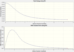
From the last point (with electronic energy = -231.68298131 Ha) on the IRC spectrum simulated, shown in Figure 15., it is clear that the structure has not reached the energy minimum yet. Therefore further simulations were carried out in the following three different ways.
Method 1 The last point on the IRC was taken and a normal optimization was ran. The resultant electronic energy is -231.68302549 Ha, which slightly lower than the first simulation. The optimized structure is shown in Figure.16.
E IRC i |
Method 2 The simulation was restarted with specified 100 points. This gives energy of -231.68298131 Ha, which is the same as the first simulation done with 50 points specified. Therefore the re-simulated geometry has not reach a minimum as well. The IRC path, displays in Figure. 17, is quite similar to the first simulation.

Method 3 The IRC was carried out again with force constants calculated at every step and no specified number of points. This time the calculated energy is -231.65069991 Ha, the lowest simulated energy among these three methods. Figure 18. shown below is the IRC spectrum for this effective simulation.
E IRC iii |

Comparison of the "Chair" and the "Boat" transition structures
The chair and boat transition structures are re-optimized by using the B3LYP/6-31G level of theory and the frequency calculations was carried out. Therefore the energies calculated by using different methods can be compared.
Summary of energies (in hartree)
| Energy | Relative Energy/Hartrees, HF/3-21G | Relative Energy/Hartrees, B3LYP/6-31G |
| Sum of electronic and zero-point Energies | -231.4667 | -234.4149 |
| Sum of electronic and thermal Energies | -231.4613 | -234.4090 |
| Sum of electronic and thermal Enthalpies | -231.4604 | -234.4081 |
| Sum of electronic and thermal Free Energies | -231.4952 | -234.4438 |
| Energy | Relative Energy/Hartrees, HF/3-21G | Relative Energy/Hartrees, B3LYP/6-31G |
| Sum of electronic and zero-point Energies | -231.4510 | -234.4023 |
| Sum of electronic and thermal Energies | -231.4453 | -234.3960 |
| Sum of electronic and thermal Enthalpies | -231.4444 | -234.3951 |
| Sum of electronic and thermal Free Energies | -231.4798 | -234.4318 |
*1 hartree = 627.509 kcal/mol
The sum of energies of the chair and the boat transition structures are summarized in Table 5. and 6.. It is noticeable that the energies calculated at the theory of B3LYP/6-31G are lower than those at HF/3-21G.
Summary of activation energies (in kcal/mol)
| Transition Structure | HF/3-21G at 0 K | HF/3-21G at 298.15 K | B3LYP/6-31G at 0 K | B3LYP/6-31G at 298.15 K |
| ΔE (Chair) | 45.68 | 44.73 | 34.07 | 33.19 |
| ΔE (Boat) | 55.61 | 54.76 | 41.96 | 41.34 |
The experimental activation energies are given to be 33.5 ± 0.5 kcal/mol and 44.7 ± 0.5 kcal/mol for chair and boat transition structures respectively. Therefore simulations at B3LYP/6-31G give closer value to the experimental.
The Diels Alder Cycloaddition
In a Diels Alder reaction, new σ bonds forms by the π orbitals of the nucleophile and of the diene. New bonding or anti-bonding MOs form by the interaction of the HOMO/LUMO of the reactants. The reaction is only allowed when the HOMO-LUMO are overlapping correctly.
The AM1 semi-empirical molecular orbital method was used for the following calculations.
Ethylene and cis-butadiene reaction
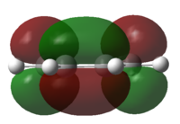
The HOMO and LUMO of cis-butadiene were plotted and the symmetry was determined.
| HOMO | LUMO | Discussion | |
| cis-Butadiene | 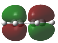
|
|
The HOMO is anti-symmetrical and the LUMO is symmetrical |
| Ethylene | 
|
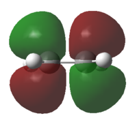
|
The HOMO is symmetrical and the LUMO is anti-symmetrical |
Calculation of ethylene + cis-butadiene transition structure
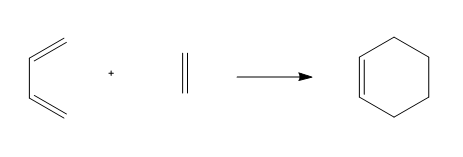
As the reaction scheme shown below in Figure 20., the reaction between ethylene and cis-butadiene gives cyclohexene.
The MOs of the transition structure were simulated and the result displays in Table 9.. The HOMO at the transition state is anti-symmetrical, thus, it is should be formed by the anti-symmetrical HOMO of the cis-butadiene fragment and the anti-symmetrical LUMO of the ethylene fragment.
| HOMO | LUMO | Discussion | |
| Ethylene-butadiene transition structure | 
|

|
The HOMO is anti-symmetrical and the LUMO is symmetrical |
As shown in Figure 21., The bond length of the partly bonded σ C-C bond of the ethylene-butadiene transition structure are calculated to be 2.12 Å. sp2 and sp3 C-C bondlengths are typically 1.476 Å and 1.537 Å respectively.[3] And the van der Waals radius of the carbon atom is 1.70 Å.[4] Therefore bond forming interaction should takes place as the simulated bondlength of 2.12 Å is within this literature value.

The vibration was animated (Figure 22.), which indicates that the formation of the two bonds are synchronous. The calculation gave an imaginary frequency of 955.67 cm-1.
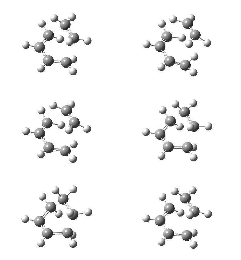
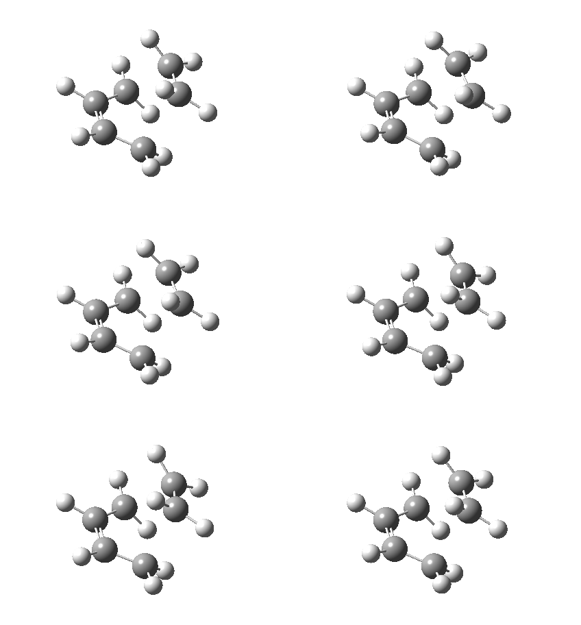
At 147.28 cm-1, the lowest positive frequency, the vibration is quite different (Figure 23.). It is not vibrating along the direction of bond forming between the two fragments but simply vibrating themselves.
Cyclohexa-1,3-diene and maleic anhydride reaction
Cyclohexa-1,3-diene reacts with maleic anhydride to give two adducts (Figure 24.), in which the endo one is believed to be the major product. In this part, to study the regiochemistry of the Diels Alder cycloaddition, the transition structures of this reaction was investigated.
Exo transition structure
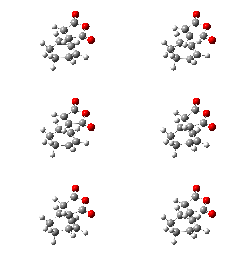
The animation of the vibrating exo transition structure displays in Figure 25., accounts for the synchronous forming of the two bonds. The magnitude of the imaginary frequency given by the calculation is 812.19 cm-1. And the partly formed σ C-C bond length is calculated to be 2.17 Å, as shown in Figure 27..
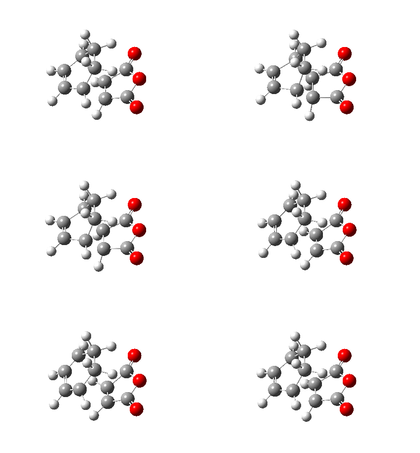
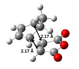
The sum of energies are list in Table 10. below and the electronic energy of this exo structure is -0.05041983 Ha by the simulation.
| Energy | Energy/Hatrees Exo |
| Sum of electronic and zero-point Energies | 0.134882 |
| Sum of electronic and thermal Energies | 0.144882 |
| Sum of electronic and thermal Enthalpies | 0.145826 |
| Sum of electronic and thermal Free Energies | 0.099118 |
| HOMO | LUMO | Discussion | |
| Ethylene-butadiene transition structure | 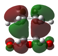
|
|
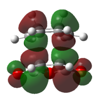
Both of the HOMO and LUMO are anti-symmetrical |
Endo transition structure
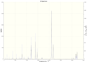
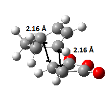
The animated vibration of the endo transition structure (Figure 28.), shows the synchronous formation of the bonds. The simulation gave an imaginary frequency of magnitude 806.22 cm-1. According to the simulation, the partially formed σ C-C bond of the endo transition structure is 2.16 Å apart (Figure 29.), which is slightly shorter than the exo one. A infrared spectrum was generated (Figure 30.).

| Energy | Energy/Hatrees Endo |
| Sum of electronic and zero-point Energies | 0.133493 |
| Sum of electronic and thermal Energies | 0.143682 |
| Sum of electronic and thermal Enthalpies | 0.144626 |
| Sum of electronic and thermal Free Energies | 0.097350 |
The electronic energy of the endo structure is computed to be -0.05150475 Ha, lower than that of the exo transition structure, indicating a more stable form of the adduct.
Comparing the sum of energies of the exo and endo adduct transition structures list in Table 11. and 12., it is noticeable that the energies of the endo structure are lower than the exo one.
| HOMO | LUMO | Discussion | |
| Ethylene-butadiene transition structure | 
|
|
Both of the HOMO and LUMO are anti-symmetrical |
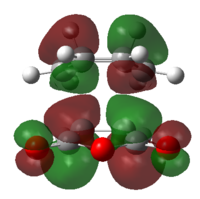
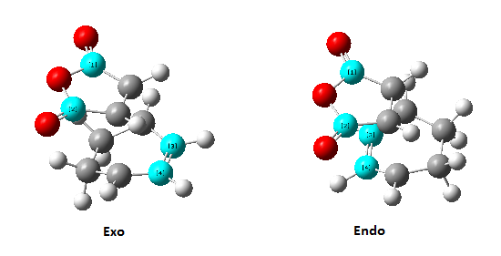
The existing secondary orbital overlap in the endo transition structure makes its formation more preferred over the exo form. In the endo form, the HOMO of the -(C=O)-O-(C=O)- fragment and the LUMO of the rest of the structure or the LUMO of that fragment and the remaining structure can overlap to form π bond; however the overlapping can not take place in the exo structure (The corresponding MOs are shown in Figure 31. in blue). This result in lower energy of the endo transition structure, thus more favorable.[5]
Reference
- ↑ J. Am. Chem. Soc., 1994, 116 (22), pp 10336–10337 DOI:10.1021/ja00101a078
- ↑ Cope, A. C.; Hardy E. M. J. Am. Chem. Soc. 1940, 62, 441.
- ↑ J M Baranowski 1986 J. Phys. C: Solid State Phys. 19 4613 DOI:10.1088/0022-3719/19/24/006
- ↑ J. Phys. Chem., 1996, 100 (18), pp 7384–7391 DOI:10.1021/jp953141+
- ↑ J. Org. Chem., 1987, 52 (8), pp 1469–1474 DOI:10.1021/jo00384a016


