Rep:Mod:STrimmer3
Module 3
Samuel Trimmer
The Cope Rearrangement
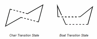
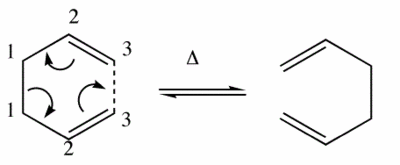
1,5-hexadiene can undergo a [3,3]-sigmatropic shift rearrangement. It's mechanism was not always known in full and has been studied in detail. It is now known that the reaction procceds in a concerted manner with a chair or a boat transition structure. Below are calculations run on gaussian to determine the low energy minimas and transition structures on the potential energy surface which will lead to determination of the reaction mechanism.
Optimising the Reactants and Products
The reactants and products of 1-5 Hexadiene has been calculated using a HF/3-21G level of theory, the memory for all the optimisation calculation was increased to 250 MB. 2 gauche structures and 2 anti periplanar stuctures were submitted as gaussian calculations and the energy and symmetry results are shown below.
| Conformer | Energy/(a.u) | Point Group | Image | |||
|---|---|---|---|---|---|---|
| Anti 1 | -231.69260 | C2 |
| |||
| Gauche 3 | -231.69266 | C1 |
| |||
| Gauche 2 | -231.69166 | C2 |
|
This table shows the energy differences between the different structures of 1-5 hexadiene and it can be seen that the lowest in energy is the gauche 3 conformer. This is counter-intuitive in a much as that normally the anti periplanar confirmations have lower energy due to the two larger groups being relatively far away from each other avoiding steric clash. But it would seem that in this case the gauche structure leads to atoms being in positions that lead to attracive van der waals interactions that make the stucture particularly stable. It is also important to note that the hartree unit used for energy may only show a small difference but when converted into joules is a significant difference.[1]
After these initial calculations were run it another method of optimisation was used as a comparison of the methods. The Ci anti conformer was drawn and optimised with a gauusian calculation using HF/3-21G and using and DFT B3LYP/6-31G. The table below displays the differences that occur in the methods.
| HF/3-21G | DFT B3LYP/6-31G | Anti 2 Ci Conformer | ||||
|---|---|---|---|---|---|---|
| Energy/(a.u) | -231.69254 | -234.6117 |
| |||
| C=C Bond length | 1.316 | 1.334 | ||||
| C-C Central Bond Length | 1.553 | 1.548 | ||||
| C1C2C3 Bond Angle | 124.805 | 125.286 |
The difference in these two methods is clear, the more accurate DFT method gives a lower energy. There is also a difference in the geometry of the molecule in which the HF method predicts a smaller C=C bond length and C1C2C3 Bond Angle, and a very similar central c-c bond lengths. The longer bond lengths maybe what lead to the lower energy as the steric hinderance may be reduced. However it is not possible to compare the two different methods in this manner, it would be better to see if the methods both showed similar trends over all the conformers and compare the values to that experimentally obtained.
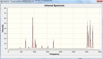
In order to ensure that the minmas have been calculated for the anti 2 conformer a frequency analysis was run If there are no imaginary (negative) frequencies then the minima has been reached. The DFT B3LYP/6-31G optimised structure was used for the frequency analysis, and the DFT B3LYP/6-31G was used as the method.
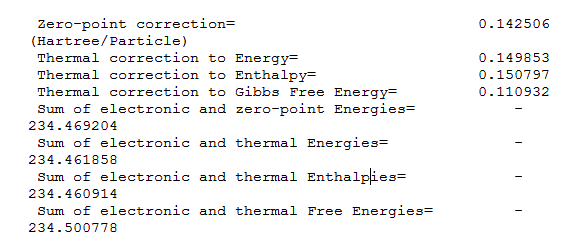
The thermodynamic energies are shown below, they are useful in comparing the energies at 298 K and at 0 K. The first value is the potential and zero-point vibrational energy at 0 K. The second value is the contributions from the translational, rotational, and vibrational energy modes at 298.15 K and 1 atm. The third contains is a correction for RT which is relevant to dissociation reactions. The final value is entropic aspect of the free energy. It is important to make sure that you select the correct energy/enthalpy term to compare to your experimental values.
Chair and Boat Transition State
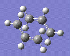
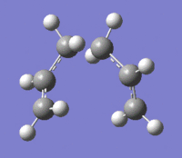
In this section the chair and boat transition state will be created and later analysed by an IRC method. an allyl fragment was initally drawn an optimised using the HF/3-21G optimisation. This allyl was then placed in an arrangement such to create the chair conformer as pictured below.
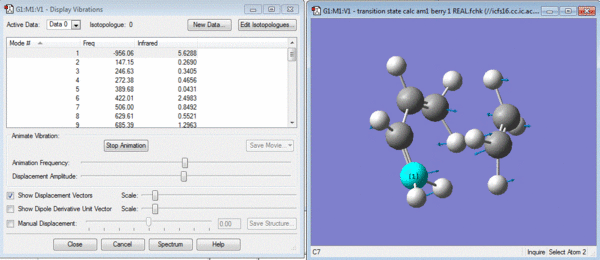
This chair conformer was optimised in two different ways. Firstly it was optimised by placing the terminal bonds approximately 2.2 angstroms apart and then a transition state calculation was run with this as an gaussian input file. The calculation was a TS(berny) calculation with force constants calculated once and Opt=Noeigen as additional keywords. This gave the structure shown below and an imaginary vibration proving that it is the transition state.
The second method of optimising the chair conformer was the frozen coordinate method in which the two terminal carbons were fixed at exactly 2.2 angstroms and then submitted to a TS(berny) calculation as previously done. The Transition state looks exactly the same except for the two fixed distance bonds which also need to be optimised. The only change is that it is the bonds that are now optimised and the force constants are not calculated.
| Frozen Method | TS(Berny) | Image | ||||
|---|---|---|---|---|---|---|
| Energy/(a.u) | -231.61932 | -231.61933 |
| |||
| Terminal Bond Length/(angstroms) | 2.02 | 2.02 |
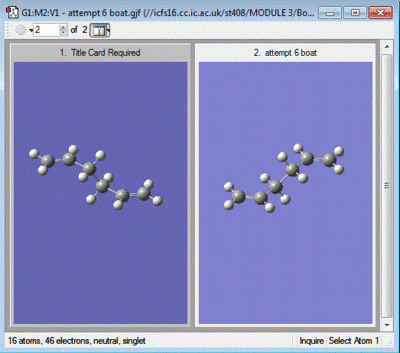
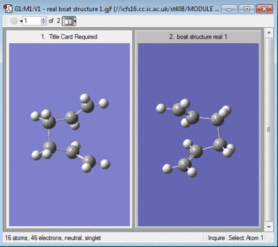
The boat transition state was next to be created and optimised. For this to be calculated the Anti2 conformer from earlier on in the module was used as a reactant and product. The atoms were relabelled for the product in order with the moving of the carbon atoms in the rearrangement reaction. In order to calculate the transition state here a different method was used called TS(QST2). This initial calculation failed to give a dissociated chair structure, in order to obtain the actual transition state the initial geometry needs changing. Images of the initial calculation structure and the changed geometry structure are shown below.
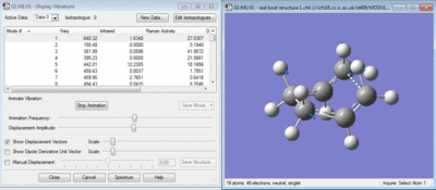
Once the correct initial geometry was used in the calculation the correct transition state was created in the TS(QST2) method and it gave an imaginary vibration shown below.
| Boat Transition State | Image | ||||
|---|---|---|---|---|---|
| Energy/(a.u) | -231.6028 |
| |||
| Terminal Bond Length/(angstroms) | 2.13 |
Intrinsic Reaction Coordinate Calculation
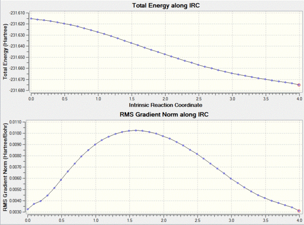
In order to actually work out where the transition structure leads to a IRC calculation is run using gaussview. This method shows the reaction proceeding to a minima on the potential energy surface. The calculation was set up in the forward direction as we are only interested in the progression from the transition state to the product. In order to avoid a slow calculation the force constants were set to only calculate once at the beginning and the number of points on the surface was set to 50.
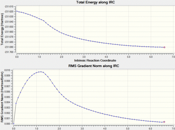
This calculation failed in such that it did not reach the final minimum, in order to reach the minimum an number of changes could be made. For example the force constants could be calculated at each point, or the number of points increased. I decided that the number of points to be increased to 200 and the force constants to be calculated at each step which as shown below gives a lower energy product from the transtition state.
Activation Energies for the Chair and Boat Transition States
In order to further analyse the chair and boat structures the activation energy has been calculated from the DFT/B3LYP method of opt-freq. The results are shown below.
| Electronic energy | Sum of electronic and zero-point energies 0 K | Sum of electronic and thermal energies 298 K | |
|---|---|---|---|
| Reactant Anti2 | -234.612 | -234.469 | -234.462 |
| Chair TS | -234.557 | -234.415 | -234.409 |
| Boat TS | -234.543 | -234.402 | -234.396 |
| Activation Energy at 0 K kj/mol | Activation Energy 298 K kj/mol | |
|---|---|---|
| Chair TS | 141.8 | 139.2 |
| Boat TS | 175.9 | 173.2 |
Approximately the boat structures activation energy is 187 kj/mol and the chair structure 140 kj/mol. This shows that the B3LYP method used is of a very good accuracy.
The Diels Alder Reaction, Ethylene and Cis-Butadiene
The reaction pictured below is a diels alder reaction between ethylene and Cis-Butadiene.
The Molecular orbitals were calculated using a semi emperical AM1 calculation for the reactants and the symmetry of the orbitals are shown in the table below.
| Reactant | Molecular Orbital | Image | Symmetry |
|---|---|---|---|
| Cis Butadiene | LUMO | 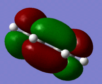 |
symmetric |
| HOMO | 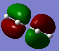 |
Antisymmetric | |
| Ethylene | LUMO |  |
Antisymmetric |
| HOMO | 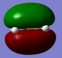 |
Symmetric |
These reactants Molecular orbitals give clues to the reaction of the molecule. Due to the orbital symmetry being as it is there is only one method that it can proceed with. The orbitals that are shown above are due to mixing of the p orbitals of each carbon. The symmetry of the HOMO and LUMO is oppoiste for each reactants. In order to see how the reaction does proceed the transition state is optimised.
The transition state was created by placing the ethylene fragment approximately 2 angstroms away from the terminal carbons of the cis-butadiene. The transition state was calculated with the TS(berny) method as used earlier on in the module. This did indeed give a transition state shown below along with the molecular orbitals.
| Molecular Orbital | Image | Symmetry | Transition State | |||
|---|---|---|---|---|---|---|
| LUMO | 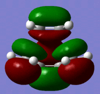 |
Symmetric |
| |||
| HOMO | 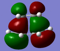 |
Antisymmetric |
These molecular orbitals follow what was predicted from the reactant molecular orbitals. The transition state has been created as can be seen by the negative vibration pictured above. The bond lengths give further information as two which bonds may be breaking and which ones are forming. The double bonds of the cis butadiene in the transition state are 1.4 angstroms long, where as the normal length of this bond should be 1.34 angstroms. This shows that these double bonds are breaking in the reaction. The single c-c bond in the transition state has a length of 1.38 angstroms. A normal c-c bond is 1.55 angstroms showing that a double bond is being formed here.
Cycloaddition of 1-3 Cyclohexadiene and Maleic Anhydride
The cycloaddition reaction between 1-3 cyclohexadiene and maleic anhydride is another example of a diels alder reaction except that in this reaction there is a possibility of two different products being formed as shown below.
| Endo | Exo | |||||||
|---|---|---|---|---|---|---|---|---|
| Energy/(a.u) | -0.0515 | -0.05050 | ||||||
| Forming C-C Bond Length/(angstroms) | 2.16 | 2.17 | ||||||
| Image |
|
|
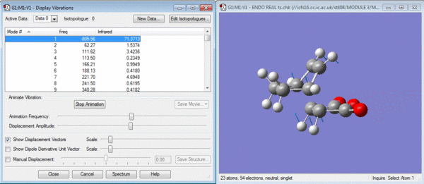
The structures have both reached transition states as shown by the negative vibrations pictured below.
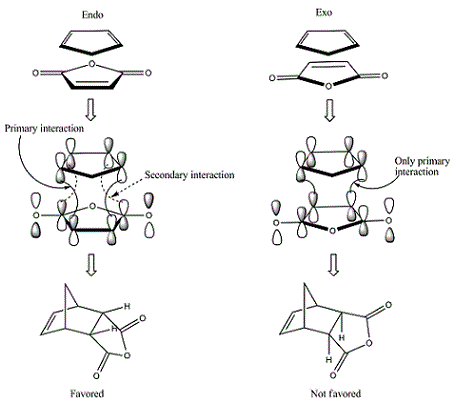
In general it would be expected that the product with the least steric hinderance would be the lowest in energy. In this case it would be the exo product as the maleic anhydride would point away from the hexadiene. The endo product is subject to further 1-3 diaxial compression and would normally be the higher energy product. However it can be seen from the data above that the endo product is lower in energy. This is due to secondary orbital overlap[2] which can be seen from a study of the molecular orbitals of the transition states shown below.
| Reactant | Molecular Orbital | Image | Symmetry |
|---|---|---|---|
| Endo | LUMO | 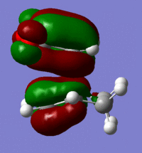 |
symmetric |
| HOMO | 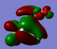 |
Antisymmetric | |
| Exo | LUMO |  |
Antisymmetric |
| HOMO | 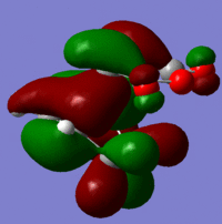 |
Symmetric |
These give much more detail as to why the endo strucutre is much more stable. It can be seen in the exo HOMO and LUMO orbitals that the p orbitals perpendicular to the plane of each molecule are interacting but they are only interacting singularly. Secondary orbital overlap can stabilise a molecule but the more orbitals that overlap the better, in other words two interactions are better than one. The Endo HOMO LUMO orbitals clearly show two separate orbital interactions. These interactions are better explained by the image shown below.

