Rep:Mod:Rachel Gregory Mod3
Introduction
The aim of this investigation is to characterise transition states on the potential energy surfaces (PESs) of the Diels-Alder cycloaddition and the Cope Rearrangement.
The Cope Rearrangement
The Cope rearrangement is an organic reaction developed by [Arthur C. Cope] and involves the 3,3-sigmatropic rearrangement of a 1,5-diene [1][2] [3] [4]. The Cope reaction is concerted and pericyclic, and in cyclohexadienes the "chair" and less-common "boat" transition structures are observed.
The Cope Rearrangement of 1,5-hexadiene
The objective of these calculations is to locate the low-energy minima and transition structures on the 1,5-hexadiene potential energy surface in order to determine the reaction mechanism by which the rearrangement proceeds.
For these calculations the B3LYP/6-31G* level of theory has been shown to give accurate activation energies and enthalpies, when compared to experimental values.
There are theoretically 27 conformational isomers of 1,5-hexadiene, and in this study a selection of the isomers are investigated. It has been found that 10 of these isomers are energetically different [5] due to the symmetry and enantiomerism of the molecule. There are several contributing factors that determine the energy level of the conformer, including, but not limited to, Paul repulsions, orbital overlap and van der Waals' interactions.
The ten distinguishable conformers of 1,5-hexadiene were drawn in GaussView5.0 in the anti formation and the structure was cleaned up. A calculation was run using the Hartree-Fock 321G basis set on Gaussian. The energy of the optimised molecule was found to be -232.25092616 au (609.8 MJ mol-1).
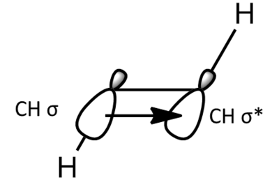
The gauche conformers, as expected, are lower in energy. This is due to sigma-conjugation (hyperconjugation. Sigma-conjugation is where the C-H σ bond donates electron density into the antibonding orbital of the adjacent periplanar CH bond, resulting in a stabilisation. The stabilisation provided by sigma conjugation is additive and so the conformer with the most hyperconjugations is the most energetically stable conformer. The energy obtained for the conformer with Ci symmetry, Anti 4, is 5 x 10⁻⁶ au higher than the energy obtained in Appendix 1.
| Information | Anti 1 | Anti 2 | Anti 3 | Anti 4 | Gauche 1 | Gauche 2 | Gauche 3 | Gauche 4 | Gauche 5 | Gauche 6 | ||||||||||||||||||||||||||||||
|---|---|---|---|---|---|---|---|---|---|---|---|---|---|---|---|---|---|---|---|---|---|---|---|---|---|---|---|---|---|---|---|---|---|---|---|---|---|---|---|---|
| Structure |
|
|
|
|
|
|
|
|
|
| ||||||||||||||||||||||||||||||
| File Type | .chk | .log | ||||||||||||||||||||||||||||||||||||||
| Calculation Type | FOPT | |||||||||||||||||||||||||||||||||||||||
| Calculation Method | FOPT | |||||||||||||||||||||||||||||||||||||||
| Basis Set | 3-21G | |||||||||||||||||||||||||||||||||||||||
| Final Energy/au | -231.68907065 | -231.6909705 | -231.69260237 | -231.69253527 | -231.69266120 | -231.68916020 | -231.68771617 | -231.69153034 | -231.69166701 | -231.68961574 | ||||||||||||||||||||||||||||||
| Relative Energy/kcal mol-1 | 2.253 | 1.061 | 0.037 | 0.079 | 0.000 | 2.197 | 3.103 | 0.710 | 0.624 | 1.911 | ||||||||||||||||||||||||||||||
| Gradient/au | 0.00001050 | 0.00001454 | 0.00000624 | 0.00001582 | 0.00000955 | 0.00000669 | 0.00000542 | 0.00000787 | 0.00000671 | 0.00001402 | ||||||||||||||||||||||||||||||
| Dipole Moment/Debye | 0.0005 | 0.2957 | 0.2021 | 0.0002 | 0.3409 | 0.5361 | 0.4557 | 0.1281 | 0.3805 | 0.4439 | ||||||||||||||||||||||||||||||
| Point Group | C2h | C1 | C2 | Ci | C1 | C1 | C2 | C2 | C2 | C1 | ||||||||||||||||||||||||||||||
| Job CPU Time/seconds | 29.0 | 15.0 | 23.0 | 25.0 | 24.0 | 44.0 | 24.0 | 31.0 | 32.0 | 24.0 | ||||||||||||||||||||||||||||||
| .log file | Conformer 1 | Conformer 2 | Conformer 3 | Conformer 4 | Conformer 5 | Conformer 6 | Conformer 7 | Conformer 8 | Conformer 9 | Conformer 10 | ||||||||||||||||||||||||||||||
Further Optimisation of the Anti 4 Conformer
The .log file obtained from the HF/321G optimisation of conformer Anti 4 was opened in GaussView and the optimisation was re-run using the B3LYP/6-31G* basis set, generating this .log file. The Results Summary from the optimisation is shown below:
| File Type | .log |
| Calculation Type | FOPT |
| Calculation Method | RB3LYP |
| Basis Set | 6-31G(d) |
| Final Energy /au | -234.61170266 |
| Gradient | 0.00001312 |
| Dipole Moment/Debye | 0.0000 |
| Point Group | CI |
| Calculation Time/seconds | 93.0 |
The final energy obtained using this basis set is 2.92 au lower than obtained previously using the lower basis set.
Comparison of Anti 4 Structures
| HF/321G | B3LYP/631G* | ||||||
|---|---|---|---|---|---|---|---|
|
|
On first inspection, both structures appear to be very similar.The C=C bond length in the HF/321G optimised structure is 1.32 Å, whereas in the B3LYP/631G* structure it is 1.33 Å. The slight increase in bond length may account for some increase in stability because it is closer to the optimum value. The C=C-C bond angle in the HF/321G optimised structure is 124.8° whereas in the B3LYP/631G* structure it is 125.3°. The C-C bond lengths are slightly shorter in the structure optimised using the higher basis set whilst the CH bond length are 0.01 Å longer in the structure optimised with the higher level basis set.
Frequency Analysis of the Anti 4 Conformer
A frequency analysis was run on the .log file obtained above, again using the B3LYP/631G* method. The table of frequencies and the infrared spectrum are displayed below.
| Mode # | Frequency/cm-1 | Intensity |
|---|---|---|
| 1 | 72.69 | 0.0184 |
| 2 | 80.13 | 0.1188 |
| 3 | 119.99 | 0.0000 |
| 4 | 219.74 | 0.1592 |
| 5 | 348.85 | 0.0000 |
| 6 | 394.28 | 0.0000 |
| 7 | 461.67 | 2.8940 |
| 8 | 625.67 | 0.0000 |
| 9 | 669.40 | 20.0222 |
| 10 | 787.80 | 4.0257 |
| 11 | 938.19 | 8.8590 |
| 12 | 938.65 | 0.0000 |
| 13 | 940.11 | 64.7675 |
| 14 | 941.80 | 0.0000 |
| 15 | 1002.03 | 0.0000 |
| 16 | 1033.75 | 0.0000 |
| 17 | 1035.98 | 19.7392 |
| 18 | 1042.72 | 0.0000 |
| 19 | 1067.94 | 9.5803 |
| 20 | 1203.21 | 0.0000 |
| 21 | 1250.96 | 0.5906 |
| 22 | 1288.83 | 6.4706 |
| 23 | 1323.03 | 0.0000 |
| 24 | 1339.07 | 0.0000 |
| 25 | 1343.15 | 1.3919 |
| 26 | 1384.09 | 0.0000 |
| 27 | 1473.71 | 0.0000 |
| 28 | 1476.22 | 1.5099 |
| 29 | 1508.55 | 0.0000 |
| 30 | 1523.20 | 5.6212 |
| 31 | 1730.95 | 0.0000 |
| 32 | 1734.24 | 18.1433 |
| 33 | 3021.69 | 0.0000 |
| 34 | 3031.33 | 53.6394 |
| 35 | 3060.30 | 0.0000 |
| 36 | 3080.33 | 35.8440 |
| 37 | 3136.93 | 0.0000 |
| 38 | 3136.98 | 56.0508 |
| 39 | 3155.47 | 14.7166 |
| 40 | 3155.73 | 0.0000 |
| 41 | 3233.89 | 0.0000 |
| 42 | 3233.92 | 45.4824 |
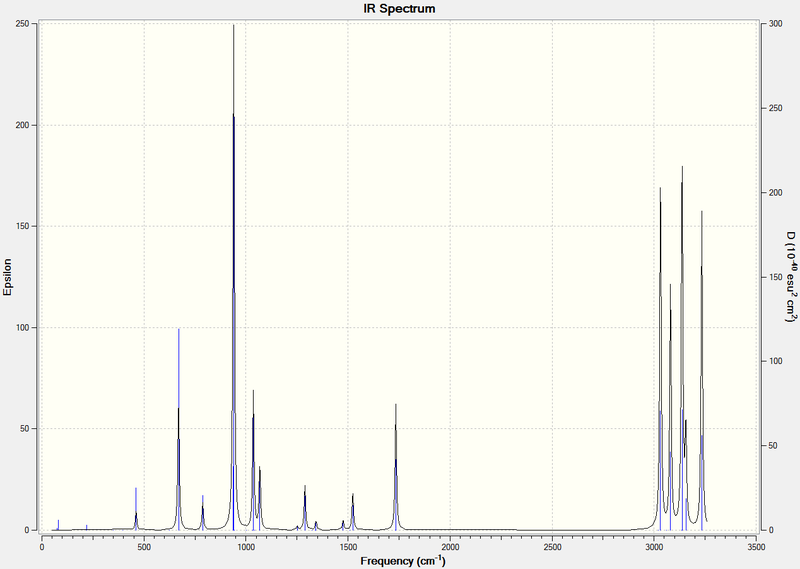
The Results File was opened and from the Thermochemistry results, the following data was obtained:
Sum of electronic and zero-point Energies=           -234.469212 Hartree/particle
Sum of electronic and thermal Energies=              -234.461856 Hartree/particle
Sum of electronic and thermal Enthalpies=            -234.460912 Hartree/particle
Sum of electronic and thermal Free Energies=         -234.500822 Hartree/particle
The same calculation was run at 1.0 Pa and 0.001 K (change in conditions obtained by using the keyword "Temperature=0.001"). This .gjf file was submitted and the following [[Media The vibrational frequencies are displayed in the table below. This had no effect on the observed vibrational frequencies or intensities shown above.
The following data were obtained from the Thermochemistry section:
Sum of electronic and zero-point Energies=           -234.469212 Hartree/particle
Sum of electronic and thermal Energies=              -234.469212 Hartree/particle
Sum of electronic and thermal Enthalpies=            -234.469212 Hartree/particle
Sum of electronic and thermal Free Energies=         -234.469212 Hartree/particle
This shows that there is no thermal energy contribution. The vibrational frequencies and intensities obtained were the same as for the calculation above at 298 K.
Optimising the "Chair" Transition Structure
Optimisation by computation of the Force Constant Matrix (The Hessian)
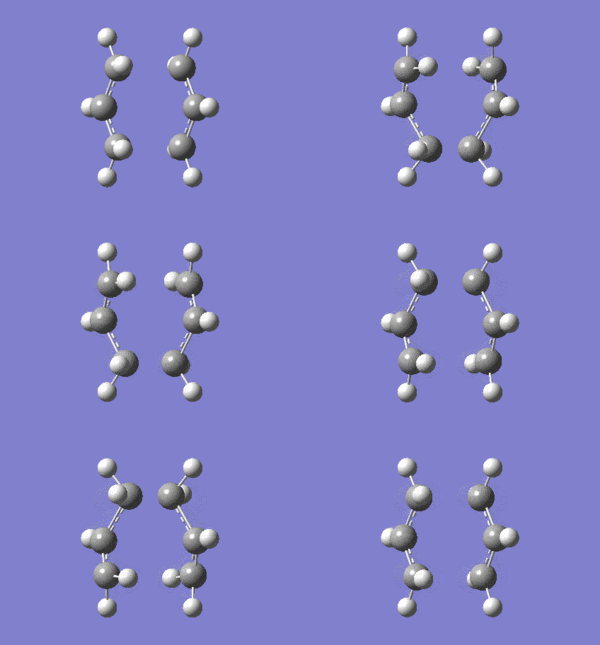
An allyl, C3H5, fragment was drawn in Gaussview and optimised using the HF/321G method. The following .log file was generated. From this optimised structure a "Chair" transition state was drawn, and the following .gjf file was submitted to Gaussian. The calculation completed and generated the following .log file. The vibrations were checked and as described in the "Chair" and "Boat Transition" Structures an imaginary vibrational frequency at 818.01cm-1 was observed with an IR intensity 5.8652. The vibration animation corresponds to the Cope Rearrangement and is shown below:
.
Optimisation using the Frozen Coordinate System
The transition state was then optimised using the frozen coordinate method. The "bond" distances between terminal carbon atoms adjacent to each other on opposite allyl fragments are frozen at 2.2 Å. The optimisation was then run with the following .gjf file, and generated the following .log file. The structure obtained is very similar to that obtained above, but the bond breaking/making distances are set to 2.200 Å, whereas in the structure obtained above the bond breaking/making distances are 2.025Å. From the .log file, the imaginary vibration was found at 817.53 cm-1 with an intensity of 5.8602. The slightly less negative vibration than found before is due to the slightly longer and therefore weaker bond. This vibration was animated and as before it corresponds to the Cope rearrangement. The vibration is imaginary (at a negative wavenumber) because
where ν is the wavenumber, c is the speed of light, k is the force constant and μ is the reduced mass.
For the vibration corresponding to the Cope rearrangement of the transition state, the force constant (a second derivative) is a negative value and so the wavenumber obtained is an imaginary number.
The .chk file was opened and the redundant coordinates were changed to find the derivative of the previously frozen bonds, and this .gjf file was submitted. Once the calculation had completed, the .log file was opened. The new breaking/making bond length was found to be 2.020 Å, slightly shorter than that found when using the method which calculate the force constant matrix.
Optimising the "Boat" Transition Structure
Optimisation using the QST2 Method
The starting molecule and product molecule were drawn in Gaussian and numbered as shown below:
| Reactant | Product | ||||||
|---|---|---|---|---|---|---|---|
|
|
This gjf.file was submitted for calculation which failed. The calculation was repeated, calculating force constants always and again failed. The .log text file was opened and the calculation had reached the maximum number of iterations without converging and so Gaussian aborted the calculation. The structure obtained was a very dissociated chair structure. The calculation was repeated using the SCF=Fermi and nosymm keywords and again the calculation failed.
The QST2 method does not consider the possibility of a rotation about the central bonds and so it will never locate the boat transition state from these reactant and product structures. The method is only reliable when reactant and product geometries are arranged in exactly the same manner
As a result, the QST2 calculation was repeated, but the reactant and product geometries were modified such that they more closely resemble the boat transition state structure, as shown below. The first time the calculation was run, the calculation did not complete and the following .log file was obtained. One of the allyl fragments has the H atoms in the incorrect orientation and the other formally has one "double bond" instead of a declocalised π system across all three carbon atoms. The structure of the initial .gjf file was modifies slightly to rotate the position of the H atom on C2. The calculation was rerun and again did not complete, generating this .log file. Again, one of the CH2 groups on C1 is in the incorrect geometry for the boat transition state, and on the other allyl fragment, the delocalised system only spreads across two of the three carbon atoms.
| Reactant | Product | ||||||
|---|---|---|---|---|---|---|---|
|
|
Optimisation using the QST3 Method
Due to the failure of the QST2 method, the QST3 method was then attempted to be run.
A transition state guess structure was added to the QST2 calculation above to generate this .gjf file. This generated the following .log file which is consistent with the boat transition structure. Although the bonds shown are drawn by GaussView as "double bonds" the bond distances between the unbonded carbon atoms are consistent with those obtained before, with a distance of 2.14 Å.
The Optimised "Boat" and "Chair" Transition Structure
| Boat Transition State | Chair Transition State | ||||||
|---|---|---|---|---|---|---|---|
|
|
From looking at the structures of the conformers and transition states it is difficult to tell which transition state connects the Cope rearrangement of different isomers. To determine which transition state is involved in the reaction, an Intrinsic Reaction Coordinate method is run
Intrinsic Reaction Coordinate Methods
Intrinsic Reaction Coordinate of the Chair Transition State
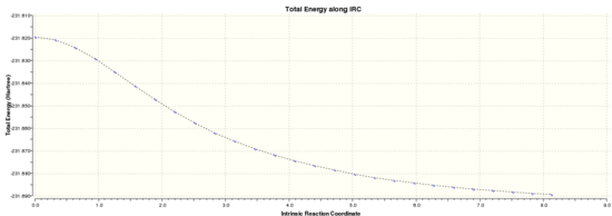
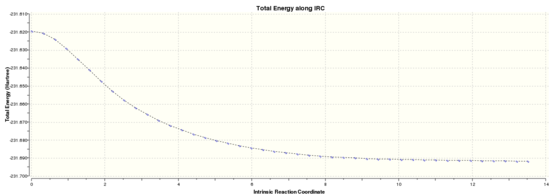
The .chk file from the optimisation of the chair transition state was opened and an Intrinsic Reaction Coordinate method was run in the forwards reaction only because the reaction coordinate is symmetric. The number of steps was set to 50. The calculation took 2 minutes. The .chk file was opened and the 27 intermediate geometries were viewed. The final energy of the 27th intermediate was -231.6891 au which corresponds to the Anti 1 conformer above. The IRC path is shown below, and from a quick analysis of the graph it does not appear that a minimum has been reached. To determine if this minimisation was an overall and not local minimum the IRC was re-run using 200 steps and calculating force constants always, generating this .log file. The final energy of the final (44th) intermediate was -231.69157889 au. This corresponds to the Gauche 4 conformer. From the graph below, it does appear that a minimisation has been reached.
| 50 Steps | 200 steps |
 |
|
Activation Energies for the Reaction
In both cases for the chair and boat transition structures, when optimised at the B3LYP/631G* level of theory the reactant has a final energy of -231.69253527 au.
The chair and boat transition structures were reoptimised from .log file 1 and [[Media:RSG_OPTANDFREQ_BOAT_QST3_ATTEMPT4.LOG|.log file 2] respectively at the B3LYP/631G* level of theory, using .gjf file 1 and .gjf file 2 respcetively, creating .log file 3 and .log file 4.
| Chair Transition State | Boat Transition State | |
|---|---|---|
| Energy of Reactants/ au | -234.61170266 | -234.61170266 |
| Energy of Products/ au | -234.55698295 | -234.54309307 |
| Activation energy/ au | 0.05472 | 0.06861 |
| Activation energy/ kcal mol-1 | -34.3 | -43.1 |
The experimental activation energies for the chair and boat transition states are 33.5 and 44.7 kcal/mol respectively [6]. The values I have obtained differ to the observed values due to errors in the calculations performed, primarily due to the method and basis set used.
Activation Energies for the Reaction via the Chair Transition Structure
The .log file was opened and an optimisation and frequency calculation was carried out using the B3LYP/6-31G* level of theory, using this .gjf file. This generated this .log file. The optimised transition structure had a final energy of -234.55698295 au (-615.8 MJ mol-1).
Activation Energies for the Reaction via the Boat Transition Structure
The .log file was opened and an optimisation and frequency calculation was carried out using the B3LYP/6-31G* level of theory, using this .gjf file. This generated this .log file. The optimised structure had a final energy of -234.54309307 au (-615.8 MJ mol-1).
The Diels-Alder Cycloaddition
The Diels-Alder cycloaddition is a pericyclic reaction in which the π orbitals of the dienophile are used to form new σ bonds with the π orbitals of the diene. The reactions can either occur in a concerted stereospecific reaction which is formally allowed or not, a formally forbidden process. For the reaction to be allowed, there must be sufficient interaction between the HOMO of one4 reactant and the LUMO of the other. In addition the overlap integral of the HOMO/LUMO orbitals should be large, and the orbitals should have the same symmetry properties. If the orbitals have different symmetry properties the reaction is forbidden. The mechanism of reaction depends on the number of π electrons involved.
cis-Butadiene
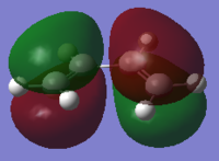
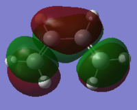
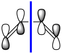
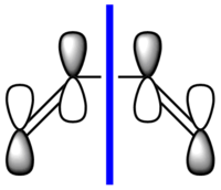
cis-butadiene was drawn in Gaussian and the structure was optimised first with the HF/321G method (.log) and then with the B3LYP/631G* method (.log file). The calculation was then run using the semi-empirical AM1 method to visualise the MOs. The following .log file was generated. The HOMO and LUMO of the optimised structure were viewed from the .chk file and are shown below. They are also shown in a schematic form. The symmetry (antisymmetric or symmetric) is defined with respect to the plane (blue line) shown in the schematics.
| HOMO | LUMO |
|---|---|
 |
|
 |
|
| Antisymmetric | Symmetric |
Computation of the Transition State Geometry for the Prototype Reaction
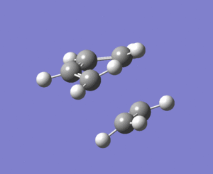
The transition state structure has an envelope type structure, which maximises the overlap between the π orbitals of the dienophile (ethylene) and the π system of the diene (butadiene).
The reactants (butadiene and ethylene) and the product (cyclohexene) were drawn in GaussView and optimised using the B3LYP/631G* basis set, to generate the following .log files: Butadiene, Ethylene, Cyclohexene. The calculation was unsuccessful on several attempts and kept getting stuck in a loop, using variants of this .gjf file.
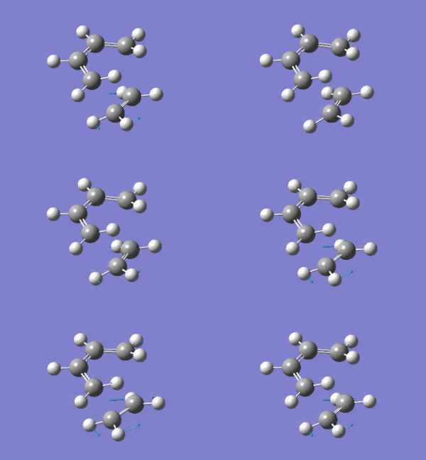
To find the transition structure, a "guess" structure was drawn in GaussView and a Berny Transition State calculation was run using the following .gjf file, generating this .log file. An imaginary vibration was found at -480.7 cm-1, showing that there is a negative force constant and so the final structure is a transition state. The imaginary vibration corresponds to the motion of the reaction, as shown below:
The formation of the bonds is synchronous. The lowest energy positive vibration at 136.3 cm-1 is illustrated below, and unlike the imaginary frequency it corresponds to an asynchronous bond vibration:
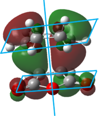
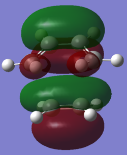
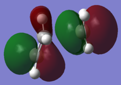
The HOMO of the transition state structure was plotted and is shown below. The HOMO has three nodal planes than run approximately in the plane of the ethylene molecule, and there is a plane of symmetry perpendicular to the plane of the butadiene molecule.
| View 1 | View 2 |
|---|---|
 |
|
test molecule |
The transition structure is shown above. The two partially formed C-C σ bonds are 2.29 Å.The ethylene fragment sp2 C=C bond length is 1.38 Å as are the C=C bonds in the butadiene fragment of the transition state. The sp3 C-C bond in the butadiene fragment has contracted to 1.41 Å. The van der Waal's radius of Carbon atoms is 1.70 Å [7]. The C-C bond length of the partly formed σ C-C bonds in he transition state is shorter than the sum of the van der Waal's radii of the two carbon atoms participating in the bonding interaction. This infers that a bond is forming.
MO Diagram for the Prototype Reaction
The MO diagram below shows the π orbitals for the reaction between cis-butadiene and ethylene. The symmetric or asymmetric character of the orbitals is determined according to the plane shown on cis-butadiene above.
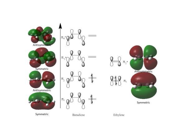
HOMO and LUMO for the Transition State of the Prototype Reaction
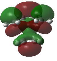
The HOMO shown is from the calculation above. The optimisation of the transition state was re-run using the AM1 method and basis set. This resulted in the two highest occupied MOs switching in energy, and the HOMO appeared to correspond more to the transition state geometry. The LUMO shown below is from the AM1 calculation.
| HOMO | LUMO | |
|---|---|---|
| Calculated MOs | 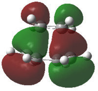 |
|
| Diagram MOs | 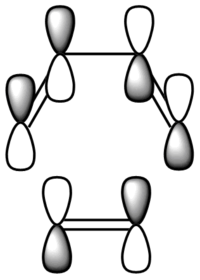 |

|
| MOs Combined | Butadiene π1 Ethylene π2* | Butadiene π3* Ethylene π1 |
| Symmetry | Antisymmetric | Symmetric |
From the symmetry of orbitals shown on the MO diagram above, orbitals of the same symmetry interact to create new orbitals which also have the same symmetry, i.e. symmetric orbitals interact with symmetric orbitals and antisymemtric orbitals interact with antisymmetric orbitals. This conforms to the Woodward-Hoffmann rules [8], [9].
Computation of the Transition State Geometry for the Reaction between cyclohexa-1,3-diene and maleic anhydride
Cyclohexa-1,3-diene (1) undergoes a facile Diels-Alder reaction with maleic anhydride (2).
| 1 | 2 |
 |

|
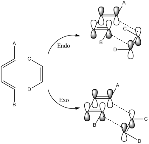
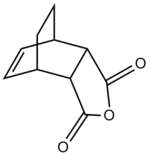
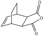
There are two possible transition structures for the reaction, the endo- and exo- forms:
| Endo- | Exo- |
 |
|
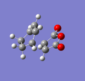
The transition state for the endo- reaction was estimated and optimised using the Berny method, with AM1 basis set. The following .log file was generated. The transition state below was found which had a final energy of -0.05150480 au (-135.2 kJ mol-1). In addition, a vibrational frequency at -806 cm-1 was observed and the vibration corresponds to the Diels-Alder reaction, see below.
| Transition State | Vibration Animation | |||
|
 |
The transition state for the exo- reaction was also estimated and optimised using the Berny method as above. The following .log file was generated for the transition state which had a final optimised energy of -0.05041985 au (-132.4 kJ mol -1). A vibrational frequency at -812 cm-1 was observed showing that there are negative force constants and so the transition state has been isolated. The vibration is shown below.
| Transition State | Vibration Animation | |||
|
 |
The endo- form is 2.8 kJ mol-1 more stable than the exo- form.
From this table the bond distances of both transition states are very similar. The main distance is the orientation of the C(=O)-O-C(=O) of the dienophile and the closes C-C bond on the diene. In the exo- transition state this distance is longer and so the secondary orbital overlap effect is weaker - the orbital overlap is proportional to the square of the distance between the atoms.
The order of orbitals and the MOs calculated does depend on the method and basis set used. Throughout these calculations the semi-empirical AM1 method and ZDO basis set has been used.
Secondary orbital overlap is when the C=O π* MO interacts with the diene HOMO resulting in stabilisation of the diene HOMO and destabilisation of the C=O π*. The diagram below shows the proposed secondary orbital overlap interactions for both exo- and endo- reactions.The presence of nodal planes between the oxygen atoms and and molecular orbitals of the diene show that there is a minimal (if any) secondary orbital overlap leading to stabilisation of the transition state. This is in agreement with several studies. In these calculations there is no solvent present in the calculations and so no solvent effects can be visualised. It appears that solvent effects have a large contribution to the stabilisation of some transition states [10]. In addition, other interactions such as Coulomb interactions also play a key role in stabilising transition states.[11].
Discussion of the Transition State Geometry for the Reaction between cyclohexa-1,3-diene and maleic anhydride
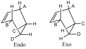
The endo- transition state has an energy of -135.2 kJ mol-1 and for the exo- transition state is -132.4 kJ mol -1. The endo form is more sterically hindered than the exo form, see the diagram below, and so is thermodynamically less stable. The additional strain results from groups C and D on the dienophile being in close proximity to groups A and B on the diene, resulting in steric clashing.
Throughout the discussion of Diels-Alder transition states several effects have been neglected. Solvation effects can be large, and changing the solvent has been found to result in large differences between the relative percentages of exo- and endo- products [12] and in addition the hydrophobic effect has also been found to result in acceleration of the Diels-Alder reaction, presumably by lowering the energy of the transition state [13]. Aqueous salt solutions have also been found to affect the reaction rate, with an increase of rate constant by a factor of 2.5 with 4.6 M LiCl, and reduction in rate constant with GnCl of up to one-third with 4.7 M GnCl [14] [15]. This effect has been attributed to changes in the Gibbs energy of solution caused by the salts breaking up the regular structure of water allowing the reactants to cavitate more easily. The rate of a Diels-Alder reaction is also enhanced in ionic liquids. This effect has been attributed to kinetic effects including solvophobic effects and internal pressure [16].
References
- ↑ Arthur C. Cope; et al.; J. Am. Chem. Soc. 1940, 62, 441
- ↑ Rhoads, S. J.; Raulins, N. R.; Org. React. 1975, 22, 1-252
- ↑ Hill, R. K.; Comp. Org. Syn. 1991, 5, 785-826.
- ↑ Wilson, S. R.; Org. React. 1993, 43, 93-250
- ↑ B. W. Gung, Z. Zhu, R. A. Fouch, Conformational study of 1,5-hexadiene and 1,5-Diene-3,4-Diols, J. Am. Chem. Soc., 1995, 117, 1783
- ↑ Dewar, M. J. S. et al., J. Am. Chem. Soc., 1977, 99 (15), pp 5069–5073
- ↑ , A. Bondi, The Journal of Physical Chemistry, 1964, 68 (3), 441-451
- ↑ R. Ponec, Overlap Determinant Method in the Theory of Pericyclic Reactions,Lecture Notes in Chemistry Volume 65, 1995, pp 10-17
- ↑ Ayers, P. W. et al., Chem. Eur. J., 2007, 13, 29, 8240–8247
- ↑ García, J. et al., Acc. Chem. Res., 2000, 33 (10), pp 658–6647
- ↑ Fox, M. A. et al., J. Org. Chem., 1987, 52 (8), pp 1469–1474
- ↑ Berson, J. A., J. Am. Chem. Soc., 1980, 102 (26), pp 7816–7817"
- ↑ Rideout, D. C>, J. Am. Chem. Soc., 1980, 102 (26), pp 7816–7817
- ↑ Breslow, R.; Rizzo, C. J. J. Am. Chem. Soc. 1991, 113, 4340.
- ↑ Breslow, R. In Structure and Reactivity in Aqueous Solutions; Cramer, C. J., Truhlar, D. G., Eds.; ACS Symposium Series 568
- ↑ Kumar, A., Chem. Rev., 101, 1, 1-19

