Rep:Mod:HAS1503
The Cope Rearrangement
Much discussion has surrounded the reaction mechanism of the [3,3]-sigmatropic shift rearrangement, and the manner in which it proceeds has been subject to some controversy. It is now believed that the reaction proceeds in a concerted fashion via either a chair or boat transition state (the chair conformation being slightly lower in energy). In the following computational investigation, the Cope rearrangement of 1,5-hexadiene shall be used to model the manner in which such a reaction progresses. Computational methods shall be used to model both the reactants/ products aswell as the possible transition states that may arise during the progression of the reaction; in this way, the lowest energy geometries of each of the aforementioned can be calculated and hence the preferred manner in which the reaction proceeds can be deduced.
Optimising the Reactants and Products
Since free rotation about single bonds within molecules is permitted, there are several possiblities for the starting geometry of 1,5-hexadiene. Whilst it is evident that sp3 hybridised carbons will favour a staggered conformation of substituents as opposed to an eclipsed orientation, the preference of such a conformation (i.e. gauche or anti-periplanar) still needs to be determined. Steric factors and stabilising interactions with unoccupied orbitals drive short chained molecules to favour entirely anti-periplanar geometries, however as chain length increases some gauche-links become favourable due to van der Waals interactions between the non-bonded atoms within the molecule. The object of this modelling is to determine which of the discussed staggered conformations is of preference in the case of 1,5-hexadiene.
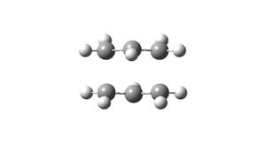
Inititally a molecule of 1,5-hexadiene was drawn with an anti-linkage between the central 4 carbon atoms. This molecule was then subjected to optimisation using the Hartree Fock method with a basis set of 3-21G. A summary of this calculation (including the optimised energy and point group) is shown in Table 1; figure 1 shows the optimised structure obtained from this calculation (3D-structure is shown via the link).
| Calculation Type | FOPT |
| Calculation Method | UHF |
| Basis Set | 3-21G |
| Total Energy (a.u) | -232.25066453 |
| Total Energy (kJ mol-1) | -609774.0315 |
| RMS Gradient Norm (a.u) | 9.94 x 10⁻⁶ |
| Dipole Moment (Debye) | 0.22 |
| Point Group | C1 |
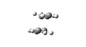
Following this a second molecule of 1,5-hexadiene was produced; in this instance the central 4 carbon atoms were modelled with a gauche-linkage. It is expected that this conformation of the molecule will have a higher energetic value than the former anti-conformer for a number of reasons. The main issue that will be mentioned here (others shall be discussed later when attempting to determine the optimum conformer) is the steric Pauli repulsions that the molecle will experience due to the closer proximity of each of the carbon groups; it is expected that these will be larger than any increase in attractive interaction within the molecule. Again, the molecule was modelled using the same method as for the anti-conformer, and a summary of the calculation is reported in Table 2; figure 2 shows the optimised geometry (3D-structure is again available via the link).
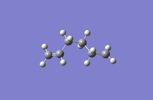
| Calculation Type | FOPT |
| Calculation Method | UHF |
| Basis Set | 3-21G |
| Total Energy (a.u) | -232.24946614 |
| Total Energy (kJ mol-1) | -609770.8851 |
| RMS Gradient Norm (a.u) | 1.49 x 10⁻⁵ |
| Dipole Moment (Debye) | 0.21 |
| Point Group | C1 |
It can be seen that as expected the gauche conformer is higher in energy that the anti conformer by around 3 kJ mol-1 which is in agreement with reported valuees. Even so, the optimum geometry may not yet determined since there are a number of different anti conformers that can be formed. By analysing each of the aspects that make geometries favourable, the optimum geometry can be predicted and confirmed using computational modelling.
It is already known that the anti-periplanar geometry is favoured; this is because this geometry minimises unfavourable Pauli repulsions between the carbon substituents resulting in a lower energetic state overall. From a steric perspective, it can be seen that this geometry is sufficiently optimised; the issue in question is now maximising favourable orbital interactions betweem the substituent hydrogens and the anti-bonding orbitals of suitably distanced groups. By positioning the one of each of the hydrogens located at carbons 3 and 4 in an eclipsed conformation with the hydrogens on carbons 1 and 6, favourable πC=C/σ*C-H and σC-H/π*C=C arise between the π-system and the remaining subtituent hydrogens. This A1,3 eclipsed conformation is also favourable from a van der Waals perspective since the distance between the eclipsed hydrogens is reported to be van der Waals attractive; hence, this also contributes to the lower overall energy of the molecular geometry1.
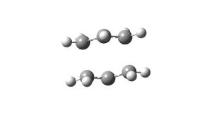
Using the same method as for the two previous calculations, the expected lowest energy conformer of the molecule was subjected to optimisation. A summary of this calculation is reported in table 3; figure 3 shows the resulting molecule.

| Calculation Type | FOPT |
| Calculation Method | UHF |
| Basis Set | 3-21G |
| Total Energy (a.u) | -231.69253525 |
| Total Energy (kJ mol-1) | -608308.6633 |
| RMS Gradient Norm (a.u) | 2.21 x 10⁻⁵ |
| Dipole Moment (Debye) | 0.00 |
| Point Group | Ci |
Oddly, this structure is determined to be of a higher energy that both of those determined previously. To ensure accuracy of the results, the previous gauche and anti-periplanar conformations were resubmitted to energy optimisation, yet both yielded the same result. Comparing the optimum structures obtained with those located in Appendix 1 of the instructions, it can be seen that the initial anti-periplanar conformer corresponds most closely to the anti-2 molecule, whilst the gauche-conformer is closest to gauche-4. It should be noted, however that both of these molecules are reported to have C2 symmetry, whereas the symmetry for the calculated molecules was only found to be C1. With regards to energies of these molecules, both of those calculated had lower energies than any of those reported within the appendix by around 1 a.u; again this questions the results obtained. Despite this, since the results were found to be reproducible, they were deemed to still be significant.
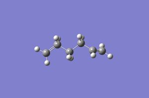
The Ci anti-2 structure of 1,5-hexadiene was created in Gaussview and initially submitted to optimisation using the HF/3-21G method and basis set. Table 4 lists a summary of this calculation; figure 4 shows the optimum structure obtained from this process.
| Calculation Type | FOPT |
| Calculation Method | RHF |
| Basis Set | 3-21G |
| Total Energy (a.u) | -231.69253515 |
| Total Energy (kJ mol-1) | -608308.663 |
| RMS Gradient Norm (a.u) | 4.55 x 10⁻⁵ |
| Dipole Moment (Debye) | 0.00 |
| Point Group | Ci |
Following this, the molecule was then submitted to optimisation using the B3LYP/6-31G* method and basis set. A summary of the calculation is reported in table 5, whilst the resulting molecule is shown in figure 5.
| Calculation Type | FOPT |
| Calculation Method | RB3LYP |
| Basis Set | 6-31G(D) |
| Total Energy (a.u) | -234.61171322 |
| Total Energy (kJ mol-1) | -615972.9369 |
| RMS Gradient Norm (a.u) | 1.29 x 10⁻⁵ |
| Dipole Moment (Debye) | 0.00 |
| Point Group | Ci |
The main noticable difference is the total energy value. The B3LYP/6-31G* method calculates a substantially lower energy conformer of the molecule than the HF/3-21G method. This is due to the higher accuracy of the method and basis type employed. A comparison of the angles and bond lengths obtained from both methods is shown in table 622.
| Method | C=C distance (Å) | C-C distance (Å) | C=C2-C3 (deg) | C2-C3-C4 (deg) |
|---|---|---|---|---|
| HF/3-21G | 1.32 | 1.51 | 125.3 | 111.4 |
| B3LYP/6-31G | 1.33 | 1.50 | 125.3 | 112.7 |
C-H dihedral angles for both compounds are comparable. It can be seen that the main differences within the geometries are a slight lengthening of the C=C double bond and a slight reduction of the C-C single bonds when using the higher accuracy method. The C2-C3-C4-C5 dihedral angle is identical for both (180 degrees). The B3LYO/6-31G method also has a slightly greater C2-C3-C4 angle than the lower accuracy optimised molecule. Both conformations show the aforementioed A1,3 eclipsed condition mentioned previously. Overalll however, there are no drastic geometrical alterations between the molecules.
A frequency calculation was performed on the Ci anti-2 conformation of the molecule to enable individual energy components of the molecule to be determined. A summary of the calculation is shown in table 7. The infra-red spectrum predicted for the compound can be found in figure 6. No imaginary vibrations were found following this calculation, indicating that the simulated molecule is at an energy minima.

| Calculation Type | FREQ |
| Calculation Method | RB3LYP |
| Basis Set | 6-31G(D) |
| Total Energy (a.u) | -234.61171322 |
| Total Energy (kJ mol-1) | -615972.9369 |
| RMS Gradient Norm (a.u) | 1.29 x 10⁻⁵ |
| Dipole Moment (Debye) | 0.00 |
| Point Group | Ci |
The thermochemical results obtained from the calculation are shown in table 8, alongside those provided in appendix 22.
| Energetic Contributions | Calcualted Results (a.u) | Appendix 1 Results (a.u) |
|---|---|---|
| Electronic + Zero Point Energy | -234.466688 | -234.469203 |
| Electronic + Thermal Energy | -234.461099 | -234.461856 |
| Electronic and Thermal Enthalpy | -234.460155 | --- |
| Electronic and Thermal Free Energy | -234.495950 | --- |
It can be seen that comparable values obtained from the computational method are higher than those located in the appendix (by a magnitude of around 10-3. This suggests that the molecule has been optimised to a slightly higher energy geometry than the one discussed in the instructions. Overall however, the agreement between the data is reasonably good.
Optimising the Transition States
As stated previously, it is known that the Cope Rearrangement proceeds via either a chair or a boat-like transition state. In the following discussion, both of these transition states shall be modelling using computational methods in an attempt to deduce which is the lower conformer and hence the more likely mechanism pathway.
Initially, an allyl fragment was created using GaussView, and optimised using the HF/3-21G method and basis set. The optimised structure from this procedure can be found in figure 7.

By manipulating two of these fragments, the transition states of the Cope Rearrangement can be modelled. The two fragments were orientated into the chair transition state, as shown in figure 8 (pre-optimisation). The first method used to optimise the transition state involved calculating the Hessian matrix. Figures 9 and 10 depict the geometric results of this calculation. Frequency analysis showed an imaginary reading at -817 cm-1, as expected, which corresponds to the Cope Rearrangement.
An alternate way of calculating the transition state is the frozen coordinate method. This method was also employed in determining the chair structure, with the co-ordinates of the terminal carbons of each of the allyl fragments being 'frozen' at 2.2Å from each other. The resulting optimum orientation of the allyl fragments is shown in figures 11 and 12.
The second transition state which the reaction may proceed via is the "boat"; the QTS2 method shall be employed for modelling this case. Initially the procedure was performed from the optimised Ci anti-2 form of 1,5-hexadiene, which resulted in the calculation failing. This was due to the reactant and product being too different from the transition state structure. The geometries of both reactant and product were manually altered so that the dihedral angle between the central four carbons was 0 degrees and the calculation was resubmitted. Table 12 reports the summary of the final calculation made. Multiple attempts were made at this procedure, however a transition state approximating that found in appendix 2 was not obtained. The closest structure yielded from the calculation is shown in figure 13; repeated errors were returned from Gaussian for all input calculations so it is known that this is obviously not an energy minima of the structure and has simply been included due to time constraints meaning that further attempts cannot be performed.
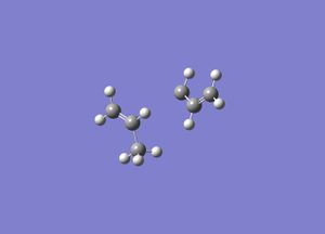
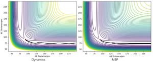
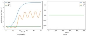
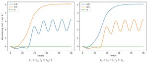
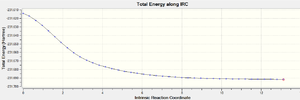
By visual examination of the boat and chair conformations, it can be deduced that the conformations of 1,5-hexadiene that they correspond to are. This method cannot be used to determine which product conformation will be favoured; instead, this must be modelled using the Intrinsic Reaction Coordinate, which models the minimum energy path from a transition state structure to the local energy minimum on a potential energy curve. To illustrate this procedure, the IRC calculation was performed upon the optimum chair geometry obtained previously. Table 12 reports the results of this calculation, while figure 14 shows a graph of the calculation progression.
| Calculation Type | IRC |
| Energy (RHF) (a.u) | -231.61932241 |
| RMS Gradient Norm (a.u) | 2.70 x 10⁻⁵ |
 |
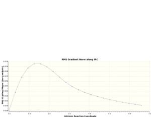 |
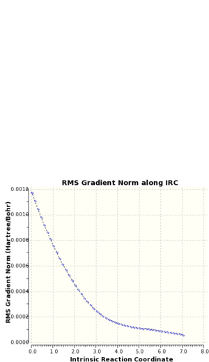
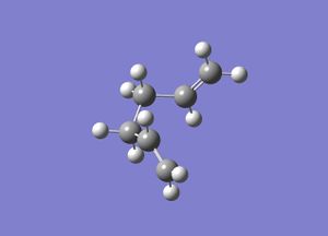
As can be seen from figure 15, the actual energy minima has not yet been determined. A second IRC was performed upon the molecule, but the force constants were calculated at every step for this repeat calculation. An optimisation calculation was performed upon the final obtained geometry of the IRC to determine to local energy minimum of the molecule. Tables 13 and 14 show a summary of the calculations; the IRC progression graphs are shown in figure 15 and the optimum geometry of the product is shown in figure 16.
 |
 |
 |
| Calculation Type | IRC |
| Energy (RHF) (a.u) | -231.686-4629 |
| RMS Gradient Norm (a.u) | 1.18 x 10⁻³ |
| Calculation Type | FOPT |
| Calculation Method | RHF |
| Basis Set | 3-21G |
| Energy (RHF) (a.u) | -231.69166702 |
| RMS Gradient Norm (a.u) | 4.36 x 10⁻⁶ |
The determined point group for the product molecule located from the IRC calculation is reported to be C2. This corresponds to the gauche-2 structure located in appendix 12.
Optimisation and frequency of the chair conformer was performed to deduce the activation energy, however since the optimum boat conformation could not be located, activation energy data was not able to be obtained and thus the lower energy barrier could not be computationally determined.
The Diels Alder Cycloaddition
The Diels Alder reaction is a specific example of a pericyclic reaction between a diene and a dienophile in which the π orbitals of the dienophile are used to form two new σ bonds through interaction with the π orbitals of the diene. Several conditions must be met for the progression os such a reaction to be permitted, which shall be discussed throughout this exercise. Two alternate forms of the reaction shall be modelled in the following exercise; initially the generic reaction shall be modelled using cis-butene and ethylene and then a further investigation shall be conducted where both the diene and dienophile contain substituent groups, allowing secondary orbital interactions to occur. The case of cyclohexa-1,3-diene and maleic anhydride shall be modelled for this latter reaction classification.
Optimisation and MO Analysis of cis-Butadiene
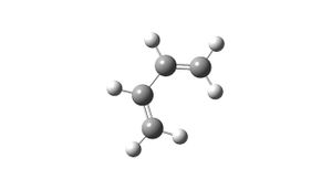
To begin, a molecule of cis-butadiene was created and submitted to Gaussian geometry optimisation. A summary of this calculation can be seen in table 19, and the optimised structure is shown in figure 19.
| Calculation Type | FOPT |
| Calculation Method | RAM1 |
| Basis Set | ZDO |
| Total Energy (a.u.) | 0.048797 |
| RMS Gradient Norm (a.u.) | 1.43 x 10⁻⁵ |
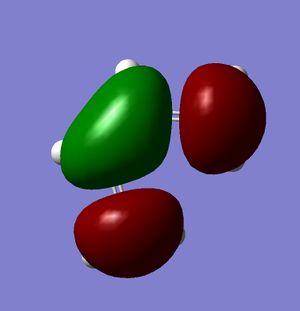
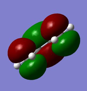
Figures 20-22 show the predicted HOMO and LUMO of the molecule, respectively. The point group of the molecule is found to be C2v. It can be seen that with regards to the plane of symmetry indicated in the instructions, the HOMO is found to be antisymmetric whilst the LUMO is symmetric.
 |
 |
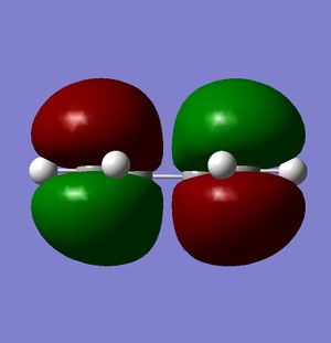 |
As mentioned previously, there are a number of criteria which must be met for a pericyclic reaction to be allowed. The first of these is that the HOMO of one molecule must be able to interact with the LUMO of the second; this is possible when both the HOMO and the LUMO of the two molecules have the same symmetry. As mentioned previously, the HOMO of cis-butadiene is symmetric with respect to the plane, and so it is this orbital which interacts; since the LUMO of ethylene is also symmetric with respect to the plane, it can be seen that the interacting orbitals have the appropriate symmetry and so the reaction is permitted.
Computation of Transition State Geometry
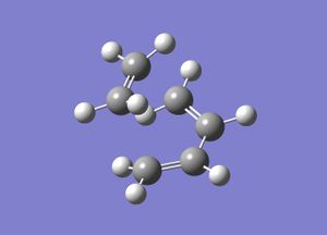
For the computation of the optimum transition state geometry, the previously modelled molecule of cis-butene and a molecule of ethylene were manually oriented into the 'envelope' structure shown within the instructions. From this, the optimum transtion state geometry could be calculated. The Freeze Coordinate system was chosen to model the optimum geometry; it was stated that previous computational analysis of this reaction had yielded a C-C bond length within the transition state of 2.273Å3, and so the terminal cis-butadiene C-ethylene C length was set to be frozen to this distance for the initial optimisation. From this, a second optimisation to a transition state was performed before the molecule was subjected to a final frequency calculation. Summaries of these 3 calculations are shown in tables 20-22. Figure 23 shows the final optimum transition state geometry. Note that for the following calculations, the HF/3-21G method and basis set was used, as the semi-empirical method yielded no appropriate results.
| Calculation Type | FTS |
| Calculation Method | RHF |
| Basis Set | 3-21G |
| Total Energy (a.u.) | -231.6032 |
| RMS Gradient Norm (a.u.) | 1.83 x 10⁻⁵ |
| Calculation Type | FOPT |
| Calculation Method | FTS |
| Basis Set | RHF |
| Total Energy (a.u.) | -231.6032 |
| RMS Gradient Norm (a.u.) | 1.83 x 10⁻⁵ |
| Calculation Type | FREQ |
| Calculation Method | RHF |
| Basis Set | 3-21G |
| Total Energy (a.u.) | -231.6032 |
| RMS Gradient Norm (a.u.) | 1.83 x 10⁻⁵ |
 |
 |
 |
 |
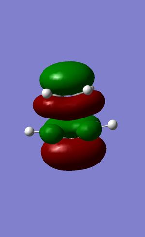
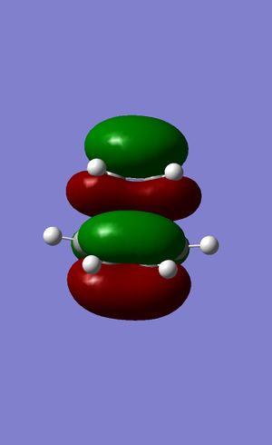
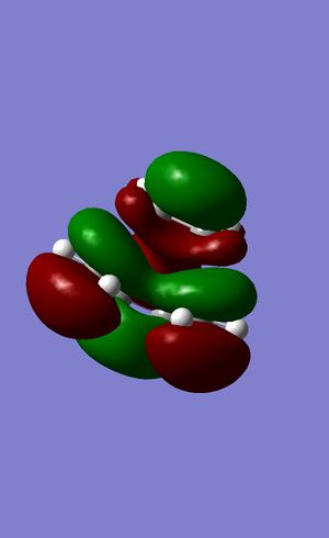
Figures 24 to 27 show the calculated HOMO and LUMO of the transition state. It can be seen that with regards to the aforementioned plane of symmetry, with are symmetric. It is clear then that the molecular orbitals involved in the formation of this structure are the HOMO of the ethylene and the LUMO of the butadiene. This is due to the matching symmetries of the orbitals which permits the reaction to proceed. The LUMO of ethylene and HOMO of butadiene cannot interact as the orbitals are of opposite symmetries which leads to a forbidden selection rule within the context of pericyclic reactions4.
Bond lengths within the transition state structure, as well as typical C-C bond lengths are shown in table 235.
| Distance (Å) | |
| Ethylene C=C | 1.36 |
| Butadiene C=C | 1.37 |
| Butadiene C-C | 1.39 |
| Terminal Butadiene C-- Ethylene C (both) | 2.21 |
| sp2 C-C | 1.33 |
| sp3 C-C | 1.53 |
It can be seen that the double bonds within both molecules are slightly longer than expected, as is the single bond within butadiene; this correlates to a weakening of the bonds upon the formation of the new sigma bonds between the two molecules. The van der Waals radius of carbon is reported to be 1.53Å6, hence it can be seen that the distance between the carbons of interest within butadiene and ethylene definitely experience some attractive interaction within the geometry obtained (since the internuclear distance is less than 3.06Å, the sum of two carbon van der Waals radii).
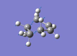
Frequency analysis of the molecule showed an imaginary frequency at -818 cm-1. This corresponds to the Diels Alder reaction. Figure 28 shows the displacement vectors of this vibration. The symmetric nature of this vibration suggests that the bonds are formed in a concerted manner. In contrast to this, the first 'real' vibration, located at 167cm-1 is an antisymmetric, consisting of the individual molecules rocking in opposite directions to one another.
Regioselectivity of the Diels Alder Reaction
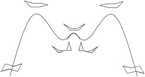
Initially, molecules of cyclohexa-1,3-diene and maleic anhydride were modelled using Gaussview and subjected to geometry optimisation. Tables 24 and 25 report summaries of these optimisations.

| Calculation Type | FOPT |
| Calculation Method | RAM1 |
| Basis Set | ZDO |
| Energy (a.u.) | -0.0565371 |
| RMS Gradient Norm | 5.69 x 10⁻⁵ |
| Calculation Type | FOPT |
| Calculation Method | RAM1 |
| Basis Set | ZDO |
| Energy (a.u.) | -0.12182418 |
| RMS Gradient Norm | 3.68 x 10⁻⁵ |
References
1. Second Year Conformational Analysis Lecture Course http://www.ch.ic.ac.uk/local/organic/conf/
2. Computational Lab Module 3 Instructions https://wiki.ch.ic.ac.uk/wiki/index.php?title=Mod:phys3
3. Goldstein et al, J Am. Chem Soc. 1996 118 (26) 6036-6043
4. Second Year Pericyclic Reactions Lecture Course http://www.ch.ic.ac.uk/local/organic/pericyclic/
5. Lide Jr., D. R.; Tetrahedron 1962 17 125-134
6. Condi, A.; J. Phys. Chem 1964 68 (3) 441-451


