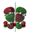
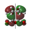
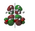
Rep:Mod:FITFPhy123
The Cope Rearrangement


The Cope rearrangement, developed by Arthur C. Cope[1], is a [3,3]-sigmatropic rearrangement of 1,5-dienes. These reactions are studied extensively both experimentally and computationally and the nature of its reaction mechanism is still a heavily debated topic [2].
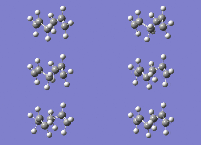
This report studies the Cope rearrangement of 1,5-hexadiene; the simplest Cope rearrangement reaction. As illustrated in Figure 1, there are three different possible reaction mechanisms[2]: (1) a stepwise mechanism involving the stable biradical immediate cyclohexane-1,4-diyl. (2) A concerted mechanism involving an aromatic (obeys Hückel's 4n+2 π electron rule) transition state. (3) A dissociative reaction mechanism via a bis-allyl intermediate. Generally, the accepted mechanism is the concerted and synchronous mechanism involving the aromatic transition state, which itself has two conformers: “chair” and “boat” as illustrated in Figure 2.
Using Gaussian 09, the different energies of the transition state structures were calculated at an ab initio level (HF/3-21G) and at a density function theory level (B3LYP/6-31G(d) - good agreement with experimental calculations[3]) to determine the preferred reaction mechanism.
Optimising the Reactants and Products
1,5-hexadiene has three free rotating carbon-carbon bonds (C2-C3,C3-C4,C4-C5) and each of these bonds has three rotational minima. Therefore, theoretically, there are twenty-seven different conformers for 1,5-hexadiene[4]. However due to the symmetry of 1,5-hexadiene and enantiomerism of some of the conformers, there are only ten energetically distinct conformers[4] (six gauche conformers and four anti conformers).
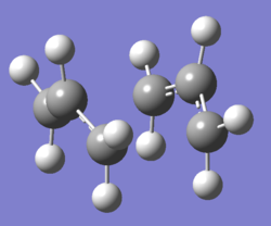
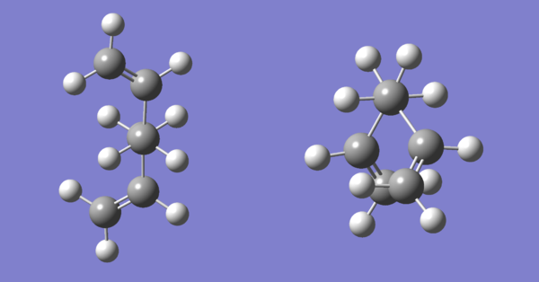
Two of these conformers, one anti or approximately antiperiplanar (dihedral angle between C2-C5 is 180°) and one gauche (dihedral angle between C2-C5 is 60°) were drawn separately on GaussView. After both structures were cleaned using the “Clean” function, the structures were optimised using calculation method Hartree Fock and basis set 3-21G. Figure 3 below shows the optimised structures for the anti and gauche conformers of 1,5-hexadiene. Table 1 below shows the calculated total energy and the point group for these conformers.
 |
| Property | Anti | Gauche |
|---|---|---|
| Total energy (a.u.) | -231.69260237 | -231.69166700 |
| Point group | C2 | C2 |
The total energy for the gauche conformer is predicted to be higher than for the anti conformer because of unfavourable steric interactions between the two vinyl groups at the end of the molecule since they are closer together in space. This is proven correct (using data in Table 1) since the total energy of the gauche conformer is higher by 0.00093537 a.u. or 0.59 kcal/mol.
The calculation of activation energies and enthalpies for a reaction are based on the conformer of the reactant with the lowest total energy[3]. Based on the results gathered from optimising the anti and gauche conformers, it is possible to predict other conformations of the molecule with a lower total energy. In the anti and gauche case, the vinyl groups in the conformers are facing the same direction and pointing towards each other respectively therefore causing steric hindrance. A lower energy conformer for both is predicted to be one where these vinyl groups are pointing in opposite direction or facing away from each other thus reducing unfavourable steric interactions. The initial anti and gauche conformers are renamed anti-fac and gauche-fac (fac = facing vinyl groups) and the new anti and gauche conformers (where the vinyl groups are facing away from each other) are named anti-opp and gauche-opp (opp = oppositely facing vinyl groups). Furthermore, it is predicted the energy of anti-opp will be lower than gauche-opp (based on previous calculations).
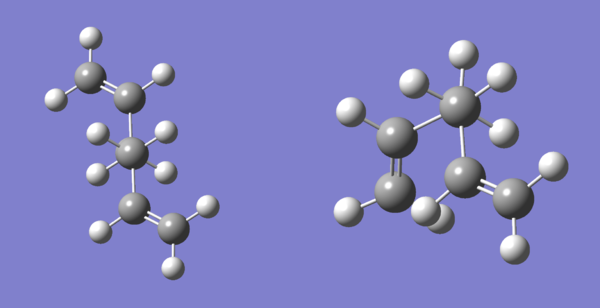
Similarly to anti-fac and gauche-fac, the structures of anti-opp and gauche-opp were separately draw on GuassView and their structures were optimised using the calculation method Hartree Fock and basis set 3-21G. The new conformers were drawn by using the optimised structures of anti-fac and gauche-fac and flipping one of its vinyl group to the other side (changing the sign of the dihedral angel between C3-C6). Figure 4 shows these optimised structures. Table 2 tabulates the data collected from optimisation.
 |
| Property | Anti-opp | Gauche-opp |
|---|---|---|
| Total energy (a.u.) | -231.69253516 | -231.69266122 |
| Point group | Ci | C1 |
Surprisingly the prediction that anti-opp will have a lower total energy than anti-fac due to less steric hindrance was incorrect since the calculated total energy is actually greater by 0.00006721 a.u. or 0.04 kcal/mol (so anti-fac is more stable).
However, the prediction that gauche-opp will have a lower total energy than gauche-fac was correct because its calculated total energy is lower by -0.00099422 a.u. or -0.62 kcal/mol. In fact this conformer has a lower total energy than the previously lowest energy conformer, anti-fac (by -0.00005885 a.u. or -0.04 kcal/mol) thus disproving the prediction that the energy of anti conformer is always lower than gauche.
Since the energy of anti-fac is lower than anti-opp and gauche-opp is lower than anti-fac, this suggests that the energies and hence stability of the conformers are not controlled by sterics (as used in the predictions), but by stereoelectronics.
Comparison with Appendix 1
Appendix 1 of the lab manual is a table containing the energies and point groups of all ten energetically distinct conformers of 1,5-hexadiene. The four computationally calculated conformers, anti-fac, gauche-fac, anti-opp and gauche-opp were compared with the same conformers from the table in Appendix 1.
| Computationally calculated conformers | Appendix 1 conformers | ||||
|---|---|---|---|---|---|
| Conformer | Point Group | Energy (a.u.) | Conformer | Point Group | Energy (a.u.) |
| Anti-fac | C2 | -231.69260 | Anti1 | C2 | -231.69260 |
| Gauche-fac | C2 | -231.69167 | Gauche2 | C2 | -231.69167 |
| Anti-opp | Ci | -231.69254 | Anti2 | Ci | -231.69254 |
| Gauche-opp | C1 | -231.69266 | Gauche3 | C1 | -231.69266 |
From Table 3, it is clear that the calculated energies of the conformers are in complete agreement with the data taken from the lab manual.
Using Appendix 1, it is confirmed the conformer out of the calculated conformers of 1,5-hexadiene with the greatest stability is gauche-opp.
Further optimisation of anti2
Anti2 (name taken from the lab manual; previously called anti-opp) was reoptimised using the calculation method B3LYP and basis set 6-31G(d) (a higher calculation method then HF/3-21G).
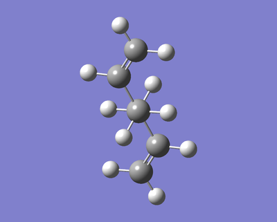 |
The recalculated energy for anti2 is -234.61171058 a.u. and the point group is Ci (did not change).
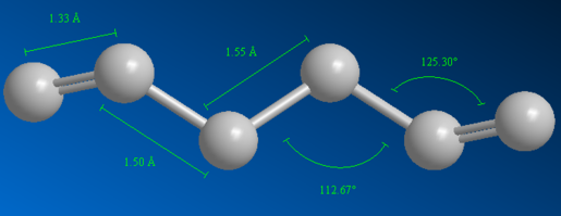
The two calculated energies for anti2 cannot be compared because different basis sets were used for each calculation. However other properties such as bond length and bond angles can be compared. Figure 6 and 7 below shows the different bond lengths and bond angles for the anti2 optimised structure using calculation methods HF/3-21G and B3LYP/6-31G(d) respectively. Table 4 below shows the optimal bond lengths and angles (taken from ChemBio3D Ultra database).
| Optimal Bond lengths (Å) | Optimal Bond angles (°) | |||
|---|---|---|---|---|
| C1-C2 | C2-C3 | C3-C4 | C1-C2-C3 | C2-C3-C4 |
| 1.34 | 1.50 | 1.52 | 109.50 | 122.00 |
The geometry of anti2 after reoptimisation undergoes some minimal changes. Firstly, the carbon double bond lengths (C1-C2 and C5-C6) have increased (by 0.018 Å) whereas the C2-C3 and C4-C5 bond lengths have decreased (by 0.005 Å). Therefore the vinyl bonds become slightly weaker whilst the C2-C3 and C4-C5 bonds become slightly stronger after reoptimisation.
There is a more significant change to the bond angles after reoptimisation. The bond angles for C1-C2-C3 (and C4-C5-C6) and for C2-C3-C4 (and C3-C4-C5) increases by 0.5° and 1.3° respectively.
Comparing this data to Table 4, the carbon bond lengths (C1-C2 and C2-C3) have become more optimal after reoptimisation. However all bond angles have become less optimal suggesting C2 and C5 have become less sp2 hybridised in character and C3 and C4 have become less sp3 hybridised in character after reoptimisation. This suggests the molecule is under more strain then intially suggested from the first optimisation.
Frequency Analysis
To compare the calculated energies for anti2 with quantities measured experimentally, a frequency calculation was carried out (on Gaussian 09 using the calculation method B3LYP and basis set 6-31G(d)). The frequency calculation is also used to confirm that the optimised anti2 structure is a minimum on the potential energy surface (critical point). This is possible because the frequency calculation is principally the second derivative of the potential energy surface therefore if all the (vibrational) frequencies are real and positive then the structure represents a minimum. (A single negative term represents a transition state.)
Taken from the output file (opened using Notepad++):
 Low frequencies ---   -9.9896   -3.4331   -0.0007   -0.0005    0.0006   22.8891
 Low frequencies ---   74.5913   81.0086  122.1831
The vibrational frequencies are characterised by the second line and since all the values are real and positive, the optimised structure of anti2 does represent a minimum on the potential energy surface.
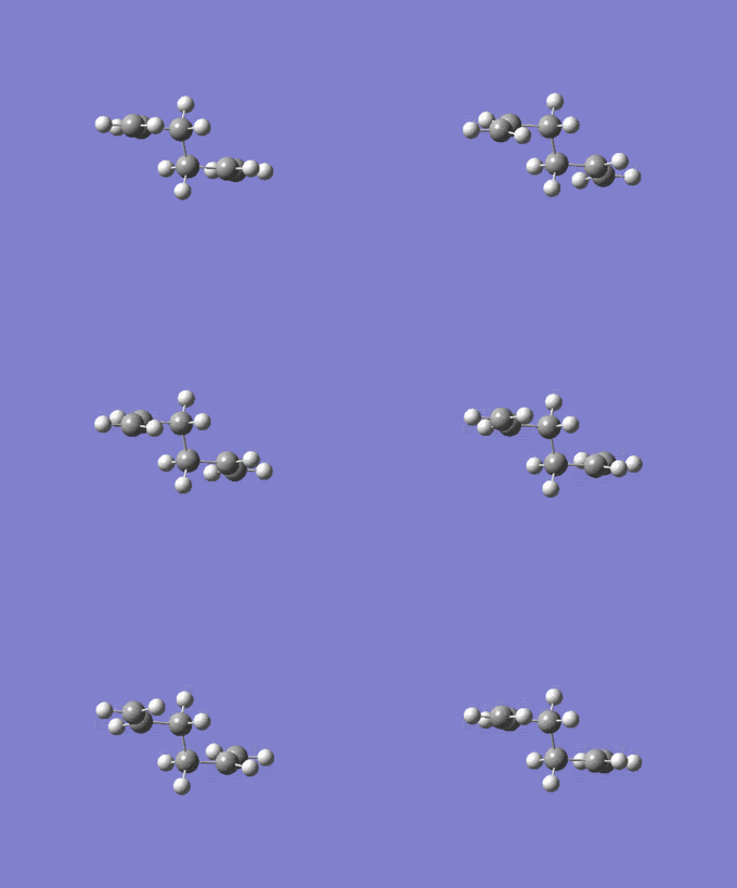
The vibrational frequencies are visualised below with a generated IR spectrum (left) and animation of the vibrational frequency at 74.6 cm-1 (right):
 |
 |
The following thermochemical data was collected from the output file:
 Sum of electronic and zero-point Energies=           -234.469203
 Sum of electronic and thermal Energies=              -234.461859
 Sum of electronic and thermal Enthalpies=            -234.460915
 Sum of electronic and thermal Free Energies=         -234.500770
The data above was tabulated in Table 5 below.
| Respective Equation | Data (a.u.) | |
|---|---|---|
| Sum of electronic and zero-point Energies | E(0K) = Eelec + ZPE | -234.469203 |
| Sum of electronic and thermal Energies | E(298K, 1 atm) = E(0K) + Evib + Erot + Etrans | -234.461859 |
| Sum of electronic and thermal Enthalpies | H = E + RT | -234.460915 |
| Sum of electronic and thermal Free Energies | G = H - TS | -234.500770 |
Using Table 5, Evib + Erot + Etrans is found to equal 0.007344 a.u. or 4.61 kcal/mol and the entropy S(298K) is found to equal 351.1 Jmol-1K-1.
Optimizing the "Chair" and "Boat" Transition Structures
In this section, the ‘chair’ and ‘boat’ aromatic transition state structures of the Cope rearrangement of 1,5-hexadiene were optimised. Transition state optimisations are more complex and difficult than the conventional optimisations (used to optimised 1,5-hexaidene conformers previously) of non-transition state structures because the calculations require the position of the reaction coordinate (the position of the negative direction of curvature)[3].
The ‘chair’ transition state structure was optimised using two methods: (1) Hessian method: computing the force constant matrix in the beginning of the optimisation (this force constant continually updates as the optimisation proceeds). (2) Frozen Coordination method: freezing the reaction coordinates and optimising the molecule conventionally. Then reoptimising the transition state with the reaction coordinates unfrozen.
The former technique works well if the drawn geometry of the transition state reasonably resembles the actual ‘chair’ transition structure of the reaction. Hence the latter works better if this is not the case.
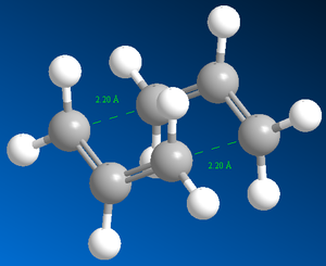
First, an allyl fragment was drawn on GaussView and optimised using calculation method Hartree Fock and basis set 3-21G. Then two of these fragments were combined and separated by a distance of 2.2 Å to guess the ‘chair’ transition state structure. This final structure was used for the methods mentioned previously.
The ‘boat’ transition state structure was determined using the QST2 method. In this method the reactant and the product were drawn and the calculations will interpolate between these two structures to find the reactions transition state[3].
Furthermore, an IRC (Intrinsic Reaction Coordinate) calculation iwas performed to generate a reaction coordinate (minimum energy path) by creating a series of points. So going from the transition state to a local minimum (the product) on the potential energy surface. The series of points are created by taking small geometry steps in the direction in which the gradient (of the potential energy surface) is steepest[3].
Finally, the activation energies for the Cope rearrangement for 1,5-hexadiene were calculated (for both ‘chair’ and ‘boat’ transition structures).
Hessian method
Keyword line for transition state optimisation by calculating force constant matrix:
# opt=(calcfc,ts,noeigen) freq hf/3-21g geom=connectivity
 |
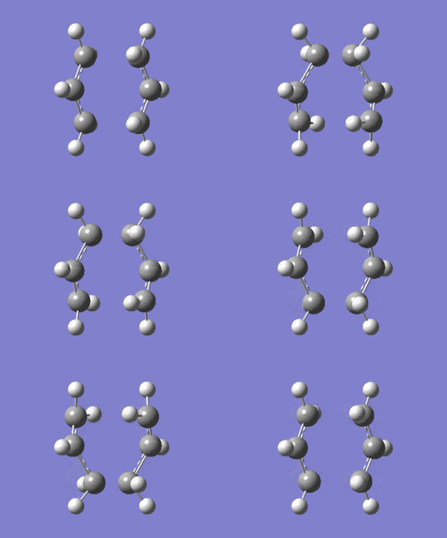 |
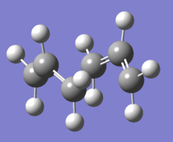
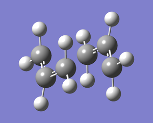
Figure 8 shows the structure of the ‘chair’ transition state after Hessian method optimisation. The energy of the structure is -231.61932221 a.u., the sum of electronic and zero-point energies is -231.466698 a.u., the sum of electronic and thermal energies is-231.461339 a.u. and the point group is C2h. These results yield good agreement with data from Result Table. Before optimisation the terminal ends of the allyl fragment were set to 2.20 Å, however after optimisation, this distance has become 2.02 Å. Furthermore the calculation gave the expected[3] imaginary vibrational mode of magnitude 818 cm-1(rounded to nearest whole number). This also confirms the structure is a transition state.
Figure 9 shows that the optimised transition structure generated is close to the actual transition state of the reaction because the terminal carbons either move towards each other indicating bond formation or away from each other indicating bond breaking.
Frozen Coordinate method
Keyword line for initial optimisation (reaction coordinates frozen):
# opt=modredundant hf/3-21g geom=connectivity
Keyword line for final transition state optimisation (reaction coordinates unfrozen):
# opt=(ts,modredundant,noeigen) freq hf/3-21g geom=connectivity
Figure 10 shows the structure of the ‘chair’ transition state after initial optimisation and it is clear that the distance between the terminal carbons of the allyl fragments have remained the same.
Figure 11 shows the structure of the ‘chair’ transition state after final optimisation and it illustrates that the distance between the terminal ends has changed to 2.02 Å (like with the previous method). The energy of the structure is -231.61932232 a.u., the sum of electronic and zero-point energies is -231.466705 a.u., the sum of electronic and thermal energies is -231.461345 a.u. and the point group is C2h. These results yield good agreement with the data collected from the Hessian method and Result Table.
The animation shown in Figure 12 is identical that of Figure 9.
QST2 method
To use the QST2 method, both the reactant and the product of the Cope rearrangement of 1,5-hexadiene were drawn on GaussView using the optimised geometry of anti2 and making sure the carbons were labelled correctly according to:

Click here to see the drawn reactant and product on GaussView.
However the calculation for optimisation using this method produced an error message on Gaussian. So the reactant and the product geometry were modified to resemble the geometry of the ‘boat’ transition state. (This was achieved by changing the dihedral angle of C2-C3-C4-C5 to 0° and changing the angles of C2-C3-C4 and C3-C4-C5 to 100°.) Click here to see the modified version of the reactant and product drawn on GaussView.
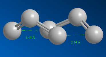
Figure 13 shows the structure of the ‘boat’ transition state after QST2 method optimisation. The energy of the structure is -231.60280249 a.u., the sum of electronic and zero-point energies is -231.450928 a.u., the sum of electronic and thermal energies is -231.445299 a.u. and the point group is C2v. These results yield good agreement with data form Result Table.
Figure 14 shows the terminal ends of the allyl fragments are separated by a distance of 2.14 Å. For the ‘chair’ transition state structure, this distance was 2.02 Å. The distance is greater for the ‘boat’ structure because it experiences eclipsing interactions which are relieved by a greater separation between the fragments. Also, there is repulsion between the flagpole hydrogens (hydrogen bonded to the centre carbon atom on the allyl fragments).
Furthermore the imaginary vibrational mode is of magnitude 840 cm-1 (rounded to nearest whole number).
Studying Figure 15 shows bond formation and bond breaking as the terminal carbons either move towards each other or away from each other, indicating the reaction going from the reactant to the product.
Intrinsic Reaction Coordinate method
It is not possible to predict which conformer the reaction paths from the transition state structures will lead to, however using IRC method (for the ‘chair’ transition structure) it is possible to calculate the conformer formed via the ‘chair’ transition state.
Keyword line for IRC method:
# irc=(forward,maxpoints=50,calcall) hf/3-21g geom=connectivity
Further explanation of keyword line above: ‘forward’ represents the direction in which the reaction coordinate goes. The forward reaction (transition state to product) was chosen instead of both directions because the reaction coordinate is symmetrical[3]. ‘Maxpoints=50’ represents the number of points (number of geometry steps taken) along IRC. ‘Calcall’ represents calculating the force constant at every step along IRC.
 |
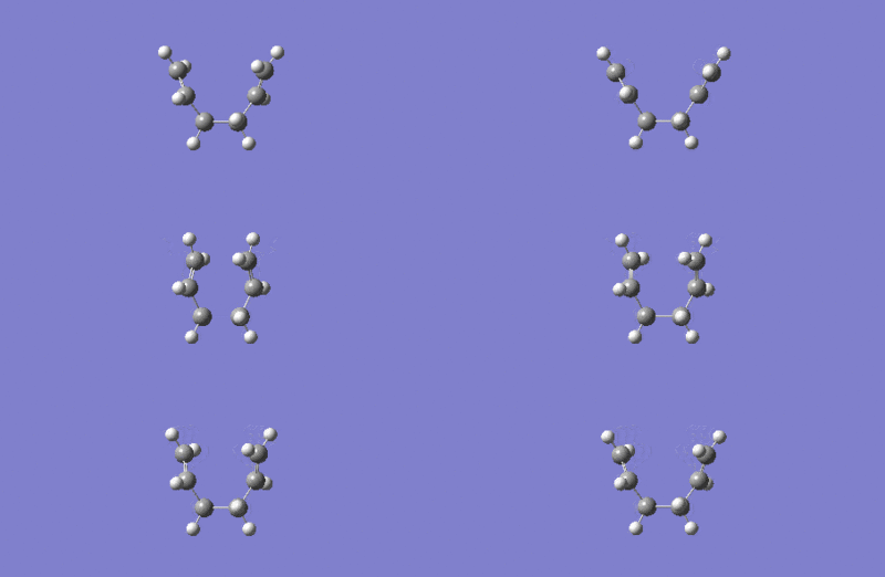 |
The lowest total energy on the IRC (Figure 16) is -231.6915782780 a.u.. This value does not match any of the energies in Appendix 1 therefore the calculation has not reached a minimum (has not reached the energy of the conformer/product). To overcome this problem, the last point structure on the IRC was optimised using HF/3-21G level of theory (so its energy can be compared with Appendix 1) to find the end conformer.
 |
Figure 18 shows the optimised structure of the last point on the IRC. Its total energy is -231.69166702 a.u. and its point group is C2. Comparing this structure to Appendix 1 shows that it is conformer gauche2. Although its energy is not the lowest out of all the possible conformations, it is still quite low and hence this structure is stable and possibly the product.
It was not necessary to increase N, the number of points, since the number of steps along the IRC stoped at 44 hence N=50 was enough. However to double check this, the IRC calculation was repeated, and the number of points was doubled (N=100). It yielded the same result (number of steps stops at 44). STOPS AT 44? IS IT NECESSARY TO DO N=100
Activation Energies
To calculate the activation energies of the reaction (via both ‘chair’ and ‘boat’ transition structures) the ‘chair’ and ‘boat’ transition structures were reoptimised using a different and higher level of theory: B3LYP/6-31G(d) (the same used for anti2 to allow for comparison).
Figure 19 shows the structure of the ‘chair’ transition state after reoptimisation. The energy of the structure is -234.55698303 a.u., the sum of electronic and zero-point energies is -234.414929 a.u., the sum of electronic and thermal energies is-234.409009 a.u. and the point group is C2h. These results closely match the data from Result Table.
Comparing Figure 11 and Figure 20, it shows that after reoptimisation using a higher a level of theory, the distance between the terminal ends of the allyl fragments change from 2.20 Å (lower level of theory used for optimisation) to 1.97 Å.
Figure 21 shows the structure of the ‘boat’ transition state after reoptimisation. The energy of the structure is -234.54309307 a.u., the sum of electronic and zero-point energies is -234.402343 a.u., the sum of electronic and thermal energies is -234.396008 a.u. and the point group is C2v. These results match the data from Result Table extremely well.
Comparing Figure 14 and Figure 22, it shows that after reoptimisation using B3LYP/6-31G(d) (high level of theory), the distance between the terminal ends of the allyl fragments change from 2.14 Å (HF/3-21G level used for optimisation) to 2.21 Å. This is an increase in distance whereas for the ‘chair’ transition structure, after reoptimisation, this distance decreased.
| HF/3-21G | B3LYP/6-31G(d) | Experimental values | ||||||
|---|---|---|---|---|---|---|---|---|
| anti2 (reactant) | Chair TS | Boat TS | anti2 (reactant) | Chair TS | Boat TS | Chair TS | Boat TS | |
| Energy (a.u.) | -231.692535 | -231.619322 | -231.602802 | -234.611710 | -234.556983 | -234.543093 | - | - |
| ΔE (a.u.) | - | 0.073213 | 0.089733 | - | 0.054727 | 0.068617 | - | - |
| ΔE (kcal/mol) | - | 45.9 | 56.3 | - | 34.3 | 43.1 | 33.5 ± 0.5 | 44.7 ± 2.0 |
Table 6 shows that the experimental values match the calculated energies using B3LYP/6-31G(d) level of theory more closely than the calculate energies using HF/3-21G level of theory. This makes sense since B3LYP/6-31G(d) is a higher level of theory and therefore produces more accurate results.
Since the activation energy going from anti2 to the ‘chair’ transition state is lower in energy than going to the ‘boat’ transition state, the Cope rearrangement of 1,5-hexadiene is likely to proceed through the ‘chair’ transition state.
The Diels Alder Cycloaddition

The Diels-Alder reaction, discovered by two German scientists, Otto Diels and Kurt Alder (ref) is a Nobel Prize winning reaction for its synthetic importance and simple operation. The reaction involves the [4+2] cycloaddition of a conjugated diene (in s-cis-conformation) and a dienophile (alkene/alkyne) to form an unsaturated six-membered ring. It involves the 4 π-electrons of the diene and the 2 π-electrons of the dienophile (hence [4+2] cycloaddition). The π orbitals of the diene and dienophile combine to form new σ bonds – it is this formation of σ bonds which drive the reaction (since σ bonds are energetically more stable than π bonds). Generally, for the π orbitals to combine, the HOMO/LUMO molecular orbitals of the diene must interact with the HOMO/LUMO molecular orbitals of the dienophile (forms new bonding and anti-bonding molecular orbitals).
Different properties of the diene (electron-rich or electron-poor) and the dienophile (presence of electron-withdrawing or electron-donating substitutes) impact the molecular orbital interactions of these two species, as well as affecting other factors such as mechanism and reaction rate.
This report studies the simplest Diels-Alder reaction: the reaction between 1,3-butadiene and ethylene. The reaction has many possible mechanistic pathways as shown by Figure 23. The different mechanism can be divided into two groups: (1) A concerted (or symmetrical) and synchronous mechanism (bond formations are simultaneous). In the transition state, the bonds forming have identical lengths. (2) A non-concerted (multistep) and asynchronous mechanism where the transition state is a biradical species. However, after comprehensive studies, it is widely accepted that the mechanism governing this reaction is likely to be concerted and synchronous (via an aromatic 'boat-like' transition state) since the transition state for the biradical mechanism is estimated to be approximately 5.7 kcal/mol higher in energy[5].
Using computational mechanical calculations, the transition state structures as well as the molecular orbitals for this reaction are studied below to computationally determine the preferred reaction pathway.
Optimising Reactants
The structure of the diene, cis-butadiene (dihedral angle between C1-C2-C3-C4 equals 0°), and the dienophile, ethylene, were drawn on GaussView and optimised using the semi-empirical AM1 method.
According to the Frontier Orbital Theory, the understanding behind the chemistry of conjugated π systems is essentially determined by the HOMO and LUMO π molecular orbitals of the reactant species. Therefore the molecular orbitals of the reactants were visualised on GaussView.
Click for the AM1 optimised structure of cis-butadiene.
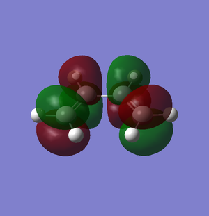
The π molecular orbitals (in order of increasing energy) of optimised cis-butadiene: π1, π2 (HOMO), π3* (LUMO) and π4* are shown below:
 |
 |
 |
 |
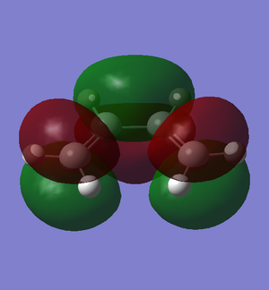
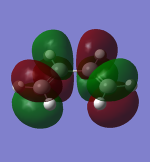
The molecular orbital calculated for π1 is incorrect, so the structure was reoptimised using a higher level of theory, B3LYP/6-31G(d), to get a better calculation therefore the correct molecule orbital for π1.
Click for the B3LYP/6-31G(d) optimised structure of cis-butadiene.
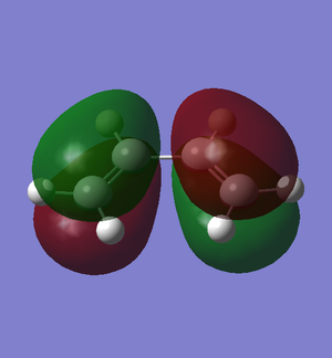
The π molecular orbitals (in order of increasing energy) of reoptimised cis-butadiene: π1, π2 (HOMO), π3* (LUMO) and π4* are shown below:
 |
 |
 |
 |
Click for the AM1 optimised structure of ethylene.
The π molecular orbitals (in order of increasing energy) of ethylene: π1 (HOMO), π2* (LUMO) are shown below:
 |
 |
Some properties of the molecular orbitals:
| Molecular orbital | Symmetry | Number of nodes | Comments | Molecular Orbital | Symmetry | Number of nodes | Comments |
|---|---|---|---|---|---|---|---|
 |
Symmetrical | 0 | The lowest occupied π molecular orbital. This molecular orbital rearranges to become the symmetric HOMO of cyclohexene. | ||||
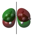 |
Asymmetrical | 1 | The highest occupied π molecular orbital (HOMO). During the Diels-Alder reaction, electrons from this molecular orbital could “flow” to the asymmetric LUMO of the ethylene, forming new δ carbon-carbon bonds. | 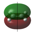 |
Symmetrical | 0 | The highest occupied π molecular orbital (HOMO). |
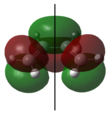 |
Symmetrical | 2 | The lowest unoccupied π molecular orbital (LUMO). During the Diels-Alder reaction, this molecular orbital allows for a favourable interaction (overlap) with the symmetric HOMO of ethylene. | 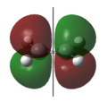 |
Asymmetrical | 1 | The lowest unoccupied π molecular orbital (LUMO). |
 |
Asymmetrical | 3 | The highest unoccupied π molecular orbital. This molecular orbital rearranges to become the asymmetric LUMO of cyclohexene. |
The energies of molecular orbitals are shown below (ethylene was reoptimised using B3LYP/6-31G(d) level of theory):
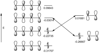 |
Transition state
The structure of the transition state of the reaction between cis-butadiene and ethylene under study is the 'boat-like' or 'envelope' concerted transition state. This structure maximises the overlap between the π orbitals of ethylene and the π system of cis-butadiene[3]. The structure was drawn on GaussView and distance between the diene and dienophile species in the transition state was guessed to be 2.2 Å. Using the Hessian method, the structure was optimised using semi-empirical AM1 method and then reoptimised using B3LYP/6-31G(d) level of theory:
The keyword line for optimisation (using semi-empirical AM1 method):
# opt=(calcfc,ts,noeigen) freq am1 geom=connectivity
Result:
         Item               Value     Threshold  Converged?
 Maximum Force            0.000021     0.000450     YES
 RMS     Force            0.000006     0.000300     YES
 Maximum Displacement     0.000576     0.001800     YES
 RMS     Displacement     0.000127     0.001200     YES
 Predicted change in Energy=-1.570719D-08
 Optimization completed.
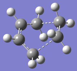 |
 |
Keyword line for reoptimisation (using B3LYP/6-31G(d) level of theory):
# opt=(calcfc,ts,noeigen) freq b3lyp/6-31g(d) geom=connectivity
Result:
         Item               Value     Threshold  Converged?
 Maximum Force            0.000018     0.000450     YES
 RMS     Force            0.000004     0.000300     YES
 Maximum Displacement     0.000361     0.001800     YES
 RMS     Displacement     0.000114     0.001200     YES
 Predicted change in Energy=-8.735816D-09
 Optimization completed.
 |
 |
 |
 |
The structure was reoptimised using B3LYP/6-31G(d) level of theory because not only did it give good (accurate) results in the previous study of the Cope rearrangement, but in literature the range of calculated distances (between the diene and dienophile species in the concerted transition state) are small for DFT: 2.27-2.28 Å[6].
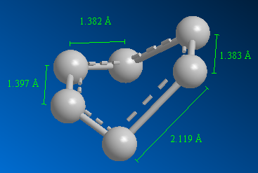
Studying Figures 25 and 27, it is clear that after reoptimising using a higher level of theory, the bonds (C-C on cis-butadiene, C-C on ethylene, C=C and the partially formed σ C-C bonds) have increased in length (0.001 Å, 0.003 Å, 0.01 Å and 0.153 Å respectively). The change is greatest for the partially formed σ C-C bonds highlighting the complexity of the calculation for partially formed bonds.
Figure 28 shows the changes in geometry of the reacting species. Ethylene’s carbons are sp2 hybridised, however these carbons in the transition state have an angle of 109.118°, signifying a change in hybridisation (carbons are now sp3 hybridised). Similarly for cis-butadiene, the C1-C2 carbons change from sp2 to sp3 hybridised, and the new angle is 102.265° (though not optimal sp3 angle yet) and the C2-C3 carbons change from sp3 to sp2 hybridised and the new bond angle is 122.034°.
Similarly the changes carbon bond lengths can be compared to signify change in hybridisation. For the ethylene species, the bond length changes from 1.337 Å to 1.386 Å (increase in length signify change to sp3 hybridised, and bond weakens since bond order decreases). For the cis-butadiene species, the bond length for C1-C2 carbons change from 1.326 Å to 1.383 Å (increase in length signify change to sp3 hybridised, and bond weakens since bond order decreases) and the C2-C3 carbons change from 1.540 Å to 1.407 Å (decrease in length signify change to sp2 hybridised, and bond strengthens since bond order increases).
Typical sp3 and sp2 carbon-carbon bond lengths are 1.54 Å and 1.34 Å respectively[7]. The van der Waals radius of carbon is 1.70 Å[8]. Though the bond length of the partially formed σ C-C bond (2.27 Å) is much greater than both sp3 and sp2 C-C bond lengths (proves σ C-C bond is not covalently bonded yet and still partially formed), it is less than the sum of two van der Waals radii of carbon. This suggest that there are some interactions, attractive, between the carbons of the partially formed σ bond.
Figure 29 shows the synchronous bond formation of two C-C bonds and atom (carbons and hydrogens) reorganisation (changes in bond length and angle) in a concerted fashion to form the planar product, cyclohexene.
Taken from the .log file:
 Low frequencies --- -525.0729   -6.3553   -0.0006   -0.0004    0.0005   10.3541
 Low frequencies ---   19.9079  135.8563  203.7389
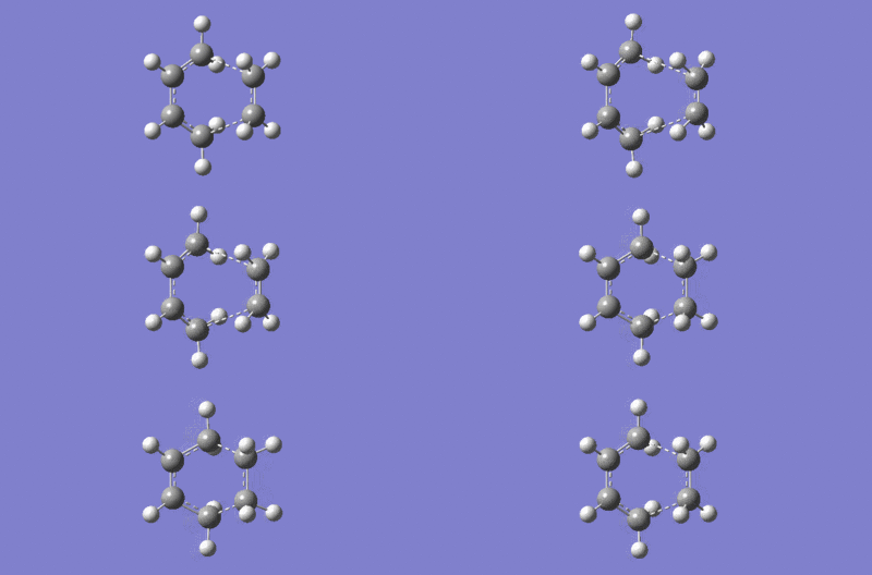
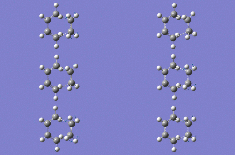
There is one imaginary vibrational mode (negative value) of magnitude 525 cm-1 thus confirming this structure is a transition state (this vibration also corresponds to the reaction path at the transition state). Therefore the formation of the two σ bonds is synchronous. The lowest positive frequency is 136 cm-1, and this frequency represents a minimum on the potential energy surface. This 'twisting' vibrational frequency is shown below:
 |
Furthermore, the point group of the transition state is Cs, which further proves the reaction occurs via a synchronous pathway because this symmetry demands a synchronous pathway for the formation of the two new C-C σ bonds[6].
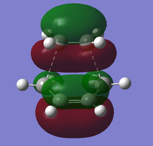
The HOMO and LUMO molecular orbitals of the transition state:
 |
 |
 |
 |
Some properties of the molecular orbitals:
The HOMO of ethylene can interact with the LUMO of cis-butadiene because they have the same symmetry (symmetric) and the orbitals are similar in energy (using Figure 24, energy difference is 0.23653). Similarly, the HOMO of cis-butadiene can interact with the LUMO of ethylene (asymmetric interaction and energy difference is 0.24616). Since the energy difference of the HOMO/LUMO interactions are similar, this reaction is thermally allowed because there is efficient orbital overlap.
The activation energies at 0K for the reaction between cis-butadiene and ethylene were calculated to be 26.1 kcal/mol and 21.2 kcal/mol using semi-empirical AM1 method and B3LYP/6-31G(d) level respectively. The experimental value for activation energy was found to be 25.1 at 0K by extrapolation of the activation energies at higher temperatures[9]. Surprising the lower level theory, semi-empirical AM1, gave a closer match to the experimental value than the higher level of theory, B3LYP/6-31G(d). However one can argue since the experimental value was extrapolated, it might be incorrect.
Studying Regioselectivity
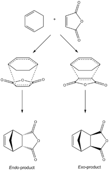
The suprafacial [4+2] cycloaddition of highly substituted dienes and dienophiles with stereogenic centres, can occur via two different transition states, the endo- and exo- transition states, each yielding adducts of differing stereochemistry. Diastereoisomers form because the diene and the dienophile can approach one another in two distinct orientations. In the endo-transition state, the substituent attached to the dienophile is directed towards the π system of the diene, whereas for the exo-transition state the substituent is directed away from it. If the substituent on the dienophile is electron-withdrawing e.g. carbonyls, the Alder endo rule states under normal conditions, the endo-transition state is preferred. This is the case with the facile reaction between 1,3-cyclohexadiene and maleic anhydride (Figure 32) which predominantly produces the endo-product. Endo- preference can be explained by secondary orbital overlap interactions (proposed by Woodward and Hoffmann [10]). Therefore to study the endo- preference for the reaction between 1,3-cyclohexadiene and maleic anhydride, the molecular orbitals of the transition state structures were studied.
The structures of the transition states of both the exo- and endo- product were determined using QST2 method. As previously mentioned, this method requires the drawn structures of the reactants and the products (on GaussView).
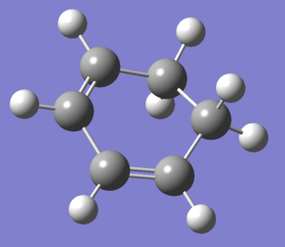
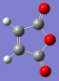
The structures of cyclohexa-1,3-diene and maleic anhydride were drawn on GaussView and optimised using B3LYP/6-31G(d) level of theory:
 |
 |
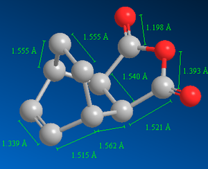
Similarly, the structure of the product, in this case, exo-product, was drawn on GaussView and optimised using B3LYP/6-31G(d) level of theory:
 |
 |
Finally, the QST2 method (optimising using semi-empirical AM1 method) was performed to predict the transition state for the reaction leading to the exo-product.
Click here to see the drawn reactants and exo-product on GaussView.
Keyword line for optimisation (semi-empirical AM1 method):
# opt=qst2 freq am1 geom=connectivity
Results:
         Item               Value     Threshold  Converged?
 Maximum Force            0.000021     0.000450     YES
 RMS     Force            0.000006     0.000300     YES
 Maximum Displacement     0.001625     0.001800     YES
 RMS     Displacement     0.000346     0.001200     YES
 Predicted change in Energy=-9.193581D-08
 Optimization completed.
 |
 |
 |
The process was repeated, but with the endo-product, to yield the transition state structure for the reaction leading to the endo-product.
Click here to see the drawn reactants and endo-product on GaussView.
Results:
         Item               Value     Threshold  Converged?
 Maximum Force            0.000019     0.000450     YES
 RMS     Force            0.000004     0.000300     YES
 Maximum Displacement     0.000693     0.001800     YES
 RMS     Displacement     0.000149     0.001200     YES
 Predicted change in Energy=-7.623807D-09
 Optimization completed.
 |
 |
 |
| Method | Exo- | Endo- |
|---|---|---|
| Semi-empirical AM1 (a.u.) | -0.15990916 | -0.16017081 |
| B3LYP/6-31G(d) (a.u.) | -612.75578545 | -612.75828992 |
| MMFF94s (kcal/mol) | -12.17 | -12.31 |
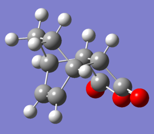
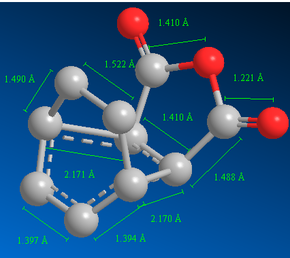
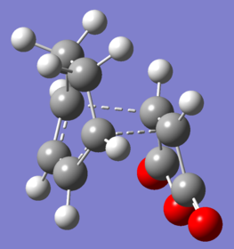
The forming σ C-C bond lengths for the exo-transition state were 2.170 Å and 2.171 Å and for the endo-transition state were both 2.162 Å (Figure 38 and 43). These values are less than the sum of two van der Waals radii of a carbon atom; therefore there are some attractive interactions between the carbons of the partially formed σ bond.
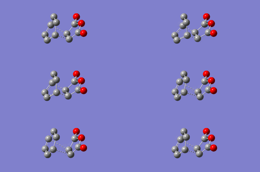
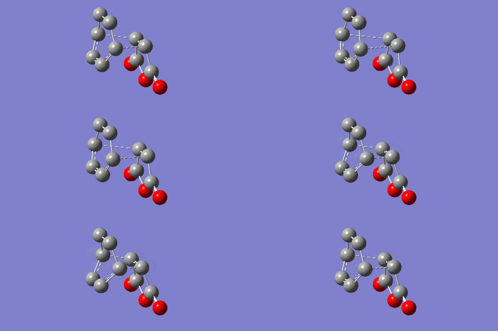
The imaginary vibrational modes (negative values) of the exo-transition state and endo-transition state are of magnitudes 812.25 and 806.42 cm-1 respectively. This confirms that both structures are transition states.
As previously mentioned, the reaction between 1,3-cyclohexadiene and maleic anhydride predominately yields the endo-product over the exo-product. The energies of the endo- and exo- transition state structures are -0.05150478 a.u. and -0.05041976 a.u. respectively. The energy of the endo-transition state is lower by 0.00108503 a.u., therefore the reaction pathway via the endo-transition state has a lower activation energy (and greater rate constant). Hence the endo-product is the kinetic product and the reaction between 1,3-cyclohexadiene and maleic anhydride is kinetically controlled under normal conditions.
Studying the structures of the transition state, it is hypothesised the exo-product is more thermodynamically stable since the endo-product has a greater torsional strain because the two rings are in an eclipsed formation leading to unfavourable van der Waals interactions. Furthermore, referring to Figures 36 and 38, bond distances are relatively shorter for the endo-product. For example, the new σ C-C bond length for exo- and endo-product is 1.562 Å and 1.559 Å respectively (C-C bond length is 0.003 Å greater for the exo-product). Hence, the endo-product is more sterically crowded which increases the energy of the system (due to unfavourable van der Waals interactions) and makes it less stable compared to the exo-product. The same applies to the transition state structures (refer to Figures 38 and 43), e.g. the bond length for the partially formed σ C-C bond is greater for the exo-transition state. Furthermore, the C-C through space distance between the -(C=O)-O-(C=O)- fragment (of the maleic anhydride) and the C atoms of the “opposite” -CH2-CH2- for the exo-transition state is 3.473 Å. The C-C through space distance between the -(C=O)-O-(C=O)- fragment (of the maleic anhydride) and the C atoms of the “opposite” -CH=CH- for the endo-transition state is 3.468 Å. This C-C through space distance is greater for the exo-transition state by 0.005 Å. Therefore the distance between these two groups is shorter for the endo-transition state hence it is more sterically crowded which increases the energy of the transition state because of steric repulsion. However the calculated energies in Table 7 do not agree with the hypothesis since the energies of the endo-product is lower than the exo-product. But since the calculated energies of the exo- and endo- product are very similar, the data may not be very reliable due to margin of error.
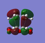
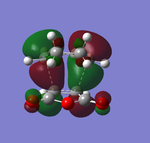
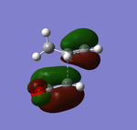
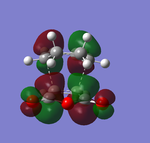
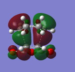
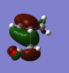
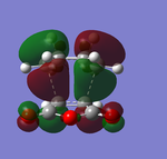
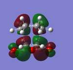
Figures 39 and 43 both show synchronous bond formation of the two new σ C-C bonds in a symmetrical and concerted manner. By studying the frontier orbitals (HUMO and LUMO orbitals) of the exo- and endo-transition states, it is possible to examine why the endo-product is the kinetic product:
The frontier orbitals of exo-transition state:
 |
 |
 |
 |
 |
 |
The frontier orbitals of endo-transition state:
 |
 |
 |
 |
 |
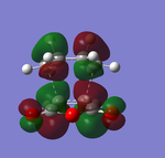 |
Both of the HOMO and LUMO orbitals for the endo- and exo- transitions states are asymmetrical, therefore these molecular orbitals arise from the overlap of the asymmetric HOMO of the of the diene (1,3-cyclohexadiene) and the asymmetric LUMO of the dienophile (maleic anhydride).
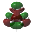
As mentioned previously, endo- preference can be explained secondary orbital overlap. Secondary orbital overlap is defined as “the positive overlap of a nonactive frame in the frontier molecular orbitals of a pericyclic reaction”[10]. Studying the side view molecular orbitals of the transition states, it is clear that there are additional non-bonding interactions between the p orbitals of the -(C=O)-O-(C=O)- substituent attached to maleic anhydride and the molecular orbitals of 1,3-cyclohexadiene for the endo-transition state since they are in close proximity and of the same symmetry (asymmetric). These interactions are absent in the exo-transition state due to a lack of proximity hence there is insufficient overlap of the molecular orbitals. This is because in the endo-transition state, the -(C=O)-O-(C=O)- substituent attached to maleic anhydride is directed towards the π system of the 1,3-cyclohexadiene, whereas for the exo-transition state the -(C=O)-O-(C=O)- substituent is directed away from it. These additional interactions, secondary orbital overlap, help to stabilse the endo-transition state, thus lowering its energy and reducing the activation energy of its reaction pathway.
Another way of looking at it is through the size of the nodal area between the -(C=O)-O-(C=O)- fragment and the rest of the transition state species (primarily the non-bonding π system of the diene). In the exo-transition state, the nodal area is large because as previously mentioned, the -(C=O)-O-(C=O)- substituent is directed away from the non-bonding π system of the diene. Therefore there is minimal interaction between the substituent and the non-bonding π system. Whereas for the endo-transition state, the nodal area is small because the -(C=O)-O-(C=O)- substituent is positioned toward the non-bonding π system of the diene. As a result, there are strong interactions between these two groups.
The activation energies at 0K for the reaction between 1,3-cyclohexadiene and maleic anhydride were calculated to be 27.8 kcal/mol and 28.7 kcal/mol via the endo-transition state and exo-transition state respectively using semi-empirical AM1 method. The activation energy for the endo-product is lower by 0.9 kcal/mol as predicted since it was found to be the kinetic product.
Further Discussion
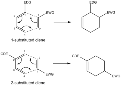
There are many other factors which affect the Diels-Alder reaction which have not been discussed: (1) Regioselectivity: the reactants of the reactions under study were all symmetrical with respect to the plane, and as a result, regioselectivity was not a concern. However when both diene and dienophile are terminally substituted and unsymmetrical, then by studying their frontier interactions (calculating orbital coefficients) and calculating their energy, one can predict the kinetic product. For example, under normal conditions, dienes bearing a substituent at C1 give an ortho product because the diene has its greatest HOMO coefficient at C4 whilst the dienophile has its greatest LUMO coefficient at C2 and the joining of these two coefficients gives the ortho product[12]. Whereas dienes bearing a substituent at C2 give a para product because the diene has its greatest HOMO coefficient at C1 while the dienophile has its greatest LUMO coefficient at C2 and the joining of these two coefficients give the para product[12]. This is illustrated by Figure 44. (2) Selectivity: due to the concerted mechanism, the Diels-Alder reactions are stereospecific, therefore the stereochemistry of the reactants is retained in the products. For example, cis and trans dienophiles give rise to products with corresponding syn or anti-stereochemistry. (3) Solvent effects: all the species discussed were in gas-phase and hence solvent effects were disregarded. It was discovered in 1980 that the reaction rate of the Diels-Alder reactions can considerably increase in aqueous solution even though pericylic reactions are generally accepted to be impervious to solvent effects[13]. For example, the rate of reaction for the reaction between cyclopentadiene and 5-methoxy-1,4-naphthoquinone was found to increase by a magnitude of 12,780 going from using n-hexane to water as the solvent[13]. Increase in reaction rate has also been observed with other polar solvents such as dimethylformamide and ethylene glycol[14]. Possible explanations include increase in the effective concentration of the reactants because of hydrophobic packing[15] and transition state stabilisation by hydrogen bonding[16]. (4) Substituents: dienes can be cyclic or open-chain and can accommodate a wide variety of substituents which can affect the reactivity of the diene. Likewise for the dienophile, for example, if the dienophile has electron-withdrawing substitutes then those substitutes can facilitate the Diels-Alder reaction because they lower the energy of the LUMO of the dienophile. A normal demand Diels-Alder reaction involves a reaction between an electron-rich diene (nucleophile) and electron-poor dienophile (electrophile). However there are reaction scenarios where the diene is electron-poor (hosts electron-withdrawing substituents) and the dienophile is electron-rich (hosts electron-donating substituents) and this type of reaction is known as inverse demand Diels-Alder reaction[17]. (5) Steric factors: often, steric effects can affect endo/exo selectivity if the diene is highly substituted or the dienophile is bulky. Furthermore, steric effects can influence the reaction rate. For example, bulky substituents on the diene positioned at C1 and C4 decrease the rate of reaction due to hindering the approach of the reactants. Whereas if the bulky groups on the diene were positioned at C2 and C3, the reaction rate increases because the substituents destabilise the trans conformation and force the diene into a reactive cis conformation[18]. (6) Pressure: the Diels-Alder reaction is an early example of a high-pressure reaction and it has been documented to show pressure induced increases in the reaction rate[19]. (7) Lewis acid activation: lewis acid catalysts such as zinc chloride, boron trifluoride, aluminum chloride, etc. can increase the rate of the Diels-Alder reaction by coordinating to the dienophile (coordination makes it more electrophilic and reactive towards the diene)[20].
References
- ↑ J. D. Roberts and J. C. Sheehan, Arthur Clay Cope, National Academy of Sciences, Washington, D.C., 1991.
- ↑ 2.0 2.1 E. Ventura, S. Andrade do Monte, M. Dallos, and H. Lischka, J. Phys. Chem. A, 2003, 107, 1175-1180. DOI:10.1021/jp0259014
- ↑ 3.0 3.1 3.2 3.3 3.4 3.5 3.6 3.7 Physical computational lab manual
- ↑ 4.0 4.1 B. W. Gung, Z. Zhu and R. A. Fouch, J. Am. Chem. Soc, 1995, 117, 1783-1788. DOI:10.1021/ja00111a016
- ↑ H. Lischka, E. Ventura and M. Dallos, ChemPhysChem, 2004, 5, 1365-1371. DOI:10.1002/cphc.200400104
- ↑ 6.0 6.1 S. M. Bachrach, Computational Organic Chemistry, Wiley-Blackwell, New Jersey, 2007.
- ↑ R. C. Weast, Handbook of Chemistry and Physics, CRC Press, Florida, 65th ed., 1984.
- ↑ A. Bondi, J. Phys. Chem., 1964, 68, 441-51. DOI:10.1021/j100785a001
- ↑ D. Rowley and H. Steiner, Discuss. Faraday Soc., 1951, 10, 198-213. DOI:10.1039/DF9511000198
- ↑ 10.0 10.1 M. A. Fox, R. Cardona, and N. J. Kiwiet, J. Org. Chem., 1987, 52, 1469-1474. DOI:10.1021/jo00384a016
- ↑ R. E. Marsh, E. Ubell and H. E. Wilcox, Acta Cryst., 1962, 15, 35-41. DOI:10.1107/S0365110X62000080
- ↑ 12.0 12.1 F. A. Carey and R. J. Sundberg, Advanced Organic Chemistry: Part A: Structure and Mechanism, Springer, New York, 5th ed., 2007, 836-50.
- ↑ 13.0 13.1 T. R. Furlani and J. Gao, J. Org. Chem., 1996, 61, 5492-5497. DOI:10.1021/jo9518011
- ↑ R. Breslow and T. Guo, J. Am. Chem. Soc., 1988, 110, 5613-5617. DOI:10.1021/ja00225a003
- ↑ R. Breslow and C. J. Rizzo, J. Am. Chem. Soc., 1991, 113, 4340-4341. DOI:10.1021/ja00011a052
- ↑ W. Blokzijl and J. B. F. N. Engberts, J. Am. Chem. Soc., 1992, 114, 5440-5442. DOI:10.1021/ja00039a074
- ↑ G. J. Bodwell, P. Zulan, I. R. Pottie, Synlett, 1999, 4, 477-479. DOI:10.1055/s-1999-2645
- ↑ D. Craig, J. J. Shipman and R. B. Fowler, J. Am. Chem. Soc., 1961, 83, 2885. DOI:10.1021/ja01474a023
- ↑ A. Vidis, G. Laurenczy, E. Kusters, G. Sedelmeier and P. J. Dyson, J. Phys. Org. Chem., 2007, 20, 109. DOI:10.1002/poc.1131
- ↑ E. B. Mubofu and J. B. F. N. Engberts, J. Phys. Org. Chem., 2004, 17, 180-186. DOI:10.1002/poc.711/pdf


