Rep:Mod:Dielsonwheels
Module 3
Ryan Spence
Introduction
In this investigation, structures of molecules at various transition states will be determined along the potential energy surface using computational methods. For this, the Cope rearrangement and Diels Alder cycloaddition will be examined by using molecular orbital based methods and Schrödinger’s equation. In addition to studying transition structures, barrier heights and reaction paths will also be calculated.
The Cope Rearrangement
The [3,3]-sigmatropic shift of 1,5-hexadiene will studied to locate the low energy minima and transition structures on the potential energy surface. This information will then be used to understand the preferred reaction mechanism.
The Cope rearrangement can be seen below along with the different transition states possible:

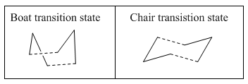
It is understood that the reaction proceeds via a chair or boat structure as the transition state, where the boat structure is higher in energy by several kcal/mol. These energies will be calculated in the following experiments using GuassView.
Optimizing the Reactants and Products
Firstly, the molecule will be optimised to find a structure with minimum energy. Using Guassian, the HF/3-21G level of theory (Hartree Fock method and 3-21G basis set) will be used. The first structure to be optimised was the approximate antiperiplanar conformation (Anti: 1) with a dihedral angle of ≈180o. Other structures were optimised as shown in the table below (Table 1). These include another antiperiplanar structure, Anti:2, and two gauche conformers, Gauche:3 and Gauche: 4, where the dihedral angle is ≈60o:
| Conformer | Anti:1 Media:rksAnti1.LOG | Anti:2 Media:rksCiOPT3.LOG | Gauche:3 Media:rksGauche3.LOG | Gauche:4 media:rksGauche4.LOG | ||||||||||||
|---|---|---|---|---|---|---|---|---|---|---|---|---|---|---|---|---|
| Jmol |
|
|
|
| ||||||||||||
| Dihedral angle C2-C5 (o) | 176.88 | 179.99 | 67.69 | 63.67 | ||||||||||||
| Calculation Type | FOPT | FOPT | FOPT | FOPT | ||||||||||||
| Calculation Method | RHF | RHF | RHF | RHF | ||||||||||||
| Basis Set | 3-21G | 3-21G | 3-21G | 3-21G | ||||||||||||
| Charge | 0 | 0 | 0 | 0 | ||||||||||||
| Spin | Singlet | Singlet | Singlet | Singlet | ||||||||||||
| Energy (a.u.) | -231.69260230 | -231.69153525 | -231.69266122 | -231.69153035 | ||||||||||||
| Appendix 1 energies (a.u.) | -231.69260 | -231.69154 | -231.69266 | -231.69153 | ||||||||||||
| RMS Gradient Norm (a.u.) | 0.00003906 | 0.00001537 | 0.00000302 | 0.00000454 | ||||||||||||
| Dipole Moment (Debye) | 0.2025 | 0.0006 | 0.3406 | 0.1280 | ||||||||||||
| Point Group | C1 | Ci | C1 | C2 |
It is expected that the antiperiplanar conformations will be the most stable because there will be less steric hindrance between the two alkene groups. This is because the groups are 180o apart compared to the compact 60o where the overlap of the pi electron clouds will repel each other. This is clearly shown by the Newman Projections below:

However, it can be seen that the gauche conformer (Gauche:3) has the lowest energy configuration. This is attributed to overlap of the C=C π orbital and the vinyl C-H σ* orbital to which electron density is favourably donated. Furthermore, the HOMO of Gauche:3 (seen below) shows a favourable overlap of both C=C π orbitals which will introduce further delocalisation of pi electrons. These two effects both contribute to the lowering of the Gauche:3 energy. However, it must be noted that the energy difference is very small and the molecule will therefore easily inter-convert at higher temperatures.
In Table 1 (above), the calculated energies were compared to previously calculated energies in Appendix 1. Comparing the two sets of values, it is seen they are both extremely similar, and hence signifying that the optimisations were successful.
Ci Anti:2 conformation
The Ci Anti:2 conformation of 1,5-hexadiene was reoptimised using the B3LYP/6-31G* level of theory, which is a more accurate method than the previous HF/3-21G used. Below (Table 2) shows the values from using both methods:
| Conformer | Anti:2 (HF/3-21G) | Anti:2 (B3LYP/6-31G) | ||||||
|---|---|---|---|---|---|---|---|---|
| Jmol |
|
| ||||||
| Calculation Type | FOPT | FOPT | ||||||
| Calculation Method | RHF | RHF | ||||||
| Basis Set | 3-21G | 6-31G(d) | ||||||
| Charge | 0 | 0 | ||||||
| Spin | Singlet | Singlet | ||||||
| Energy (a.u.) | -231.69254 | -234.55970439 | ||||||
| Appendix 1 energies (a.u.) | -231.69154 | N/A | ||||||
| RMS Gradient Norm (a.u.) | 0.000015 | 0.00000301 | ||||||
| Dipole Moment (Debye) | 0.0006 | 0.0000 | ||||||
| Point Group | Ci | Ci |
The table shows that different minimum energies were calculated when using the separate methods. However, since they are two separate calculations with different parameters, they cannot be compared. Nevertheless, the geometries can be and is shown below (Table 3):
| Dihedral angle of terminal carbons(o) | C=C bond (Å) | C2 -C3 (Å) | C3-C4 (Å) | |
|---|---|---|---|---|
| HF/3-21G | 114.73 | 1.32 | 1.51 | 1.55 |
| B3LYP/6-31G | 118.80 | 1.34 | 1.51 | 1.56 |
| Reference Values [1] | 1.34 | 1.51 | 1.54 |
As can be seen, the geometries have slightly changed upon using a different calculation method. The B3LYP/6-31G* method gives values much closer to those reported in literature. Additionally, the dihedral angle has slightly increased by approximately 4o, signifying that the latter theory is more accurate.
Frequency Analysis
Additional terms, which require a frequency calculation of the optimised B3LYP/6-31G* structure, will be calculated so that the final energies given in the output file can be compared with experimental values. Furthermore, this analysis will confirm that the minimum energy has been located in which all vibrational frequencies are real and positive.
Within the .log file, there were no negative ‘normal frequencies’ and the ‘zero frequencies’ were extremely close to 0, thus indicating that the optimisation was indeed successful. The Thermochemistry values obtained from the frequency analysis in the output file can be seen below (Table 4):
| Energy contributions | 298.15 K (a.u.) | 0 K (a.u.) | Difference (a.u.) | Difference (KJ/mol) | |
|---|---|---|---|---|---|
| Sum of electronic and zero point energies | Potential energy at 0 K and the zero-point vibrational energy: E = Eelec + ZPE | -234.416245 | -234.415805 | 0.00044 | 0.2761 |
| Sum of electronic and thermal energies | Energy at 298.15 K and 1 atm E = E + Evib + Erot + Etrans + Eelec | -234.408955 | -234.415805 | -0.00685 | -4.2984 |
| Sum of electronic and thermal enthalpies | Additional correction for: RT H = E + RT | -234.408010 | -234.415805 | -0.007795 | -4.8914 |
| Sum of electronic and thermal free energies | Entropic contribution to the free energy: G = H - TS | -234.447848 | -234.415805 | 0.032043 | 0.8719 |
As shown in the table, the values were calculated 298 K and at 0 K using the same level of theory. This was done by using the ‘Freq=ReadIsotopes’ option in Gaussian and changing the temperature, pressure and mass of each atom at the end of the file. The temperature chosen for 0 K was 0.0000001 K because a value of 0.0 K was default and simply run the calculations at 298 K when 0.0 K was used.
At 0 K, the thermal contributions to the overall energy become zero and the energy is now in the form of electronic and zero point energies.
Optimizing the "Chair" and "Boat" Transition Structures
In the following investigation, the transition states for the Cope rearrangement will be analysed. There are two transition structures: the ‘chair’ (C2h symmetry) and ‘boat’ (C2v symmetry) conformer which both consist of C3 H5 allyl fragments positioned approximately 2.2 Å apart.
The optimisations were calculated using the HF/3-21G level of theory, and initially only an allyl fragment (CH2 CHCH2) was drawn into GuassView. This was optimised and two of these fragments were combined in a new window to closely resemble the geometry of a ‘chair’ transition state in Appendix 2 where the distance between the two terminal ends was set to 2.2 Å. The transition structure optimisation was then carried out by two different ways:
i) Computing the force constants
Optimisations can be calculated using the Hessian (force constant matrix) which is updated as the optimization proceeds. However, this method only works if the initial guess for the transition structure is similar to the exact structure because the curvature of the potential energy surface may be very different when positioned away from the transition structure. To do this, the ‘Opt+Freq’ was selected, along with ‘Optimization to a TS (Berny)’. The force constants were carried out once and Opt=NoEigen was selected as an additional keyword. This was so the calculation would not crash if more than one imaginary frequency was detected during the optimization. The optimised structure can be seen in the table below (Table 5) and is identical to the structure shown in Appendix 2. Also, the frequency calculation gave an imaginary frequency of 818 cm-1 which can also be seen in Table 5.
ii) Using the redundant coordinate editor
This method can yield a better geometry for the transition structure. This is generated by freezing the reaction coordinate using the Opt=ModRedundant in GuassView and minimizing the rest of the molecule. For this, the distance between the terminal carbons of the allyl units were fixed at 2.2 Å. Once relaxed, the coordinate is then unfrozen and the transition state is optimized once more. However, the bonds that were frozen before now need to be optimised. The structure was resubmitted without any bonds frozen and was optimised to a structure at the transition state (Berny). This method is usually much less time consuming and less expensive because of the two step method of freezing and unfreezing the reaction coordinate. However, in this case, the first method was slightly faster because the initial guess of the transition structure was reasonably accurate. The results of both methods are shown below (Table 5):
file: Media:rksTRANSCHAIRBERNYANDFREQ.LOG Media:rksTRANSCHAIRFROZEN.LOG
The table shows that the values yielded (energies, terminal bond lengths, and imaginary frequencies) from both methods are identical. The bond making and braking is concerted as shown by the image above. i.e. a bond is created as another bond is broken.
Optimising the boat transition structure
The boat transition structure was optimised using the QST2 method, where the reactants and products are specified and the calculation will use these structures to interpolate between them and identify at the transition structure. The Anti:2 optimised structure was placed into the reactant and product windows. But, the reactants and products are numbered in an identical way so that atoms do not swap positions because otherwise this will fail the calculation. The numbering was done using the ‘atom list’ and can be shown below:

After this, the molecules were optimised by selecting ‘Opt+Freq’ job type was and then running the QST2 method. However, this optimisation was not successful. This was because the structures of the products and reactants were not similar to the geometry of the transition state but instead calculated a chair transition state with dissociated fragments. Here, the allyl fragements were just translated and the C-C bond was not rotated. To fix this, the dihedral angle was changed between the 2, 3, 4 and 5 atoms to be 0o and the internal C-C-C bond to be 100o . This was done for both reactant and product molecules. This is so that they resembled the boat transition structure. The numbering of the atoms was also changed like the following:

These were then optimised again to give the boat conformer as the transition state. The table below (Table 6) shows the results:
| Optimised structure (Jmol) |
| |||
| Terminal C-C bond length (Å) | 2.14 | |||
| Energy (a.u) | -231.60280049 | |||
| Imaginary frequency (cm-1) | -839 | |||
| Simulation | 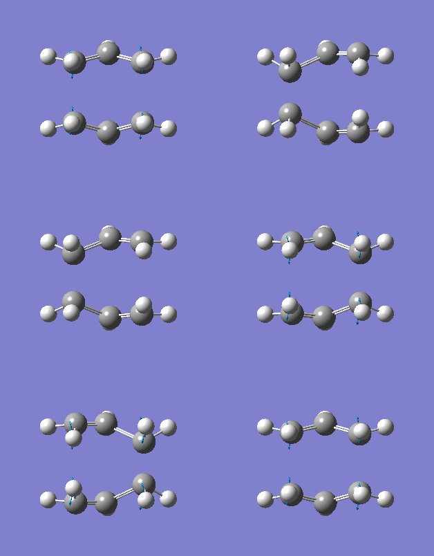
|
The reaction is still concerted (bond braking and formation) as shown by the imaginary frequency. The imaginary frequency of -840 cm-1) show that the geometry of the transition state has been correctly identified. This method (QST2) is advantageous compared to TS(Berny) at indentifying correct transition structures, however can be time consuming and fail if the reactants and products are not close to the transition structure, whereby the numbering of both molecules have to be identical.
Intrinsic Reaction Coordinate (IRC)
It is almost impossible to predict which conformer will be yielded from each transition state. Nevertheless, Gaussian allows the minimum energy pathway to be studied from the transition state to a local minimum and is known as the Intrinsic Reaction Co-oridinate (IRC) which can give confirmation of the product. This works by moving along the potential energy curve in small steps. That is, taking small geometry steps in the direction where the gradient of the curve is the largest. The Cope rearrangement is symmetric and therefore the reaction coordinated were only analysed in one direction (to save time). This was done by opening the .chk file of a chair transition state and selecting ‘forward direction’ and once for the ‘Calculate force constant’ option. The numbers of points to be calculated were set to 50 initially but the minimum geometry was not reached with this value. This could be improved by the following three options: (i) Take the last point on the IRC and run a normal minimization; (ii) Restart the IRC and specify a larger number of points until it reaches a minimum; (iii) Redo the IRC and computing the force constants at every step. There are advantages and disadvantages to each option. However, the second option will be chosen because the first option can easily go wrong and calculate the wrong minimum, and the third option is too time consuming and expensive. Therefore, a medium was found with the second option by changing the number of points to 200. The results of 50 and 200 points can be seen below (Table 7):
| IRC calculation: 50 points | IRC calculation: 200 points | |||||||
|---|---|---|---|---|---|---|---|---|
| Energy (a.u.) | -231.68719817 | -231.68290336 | ||||||
| Jmol of final structure |
|
| ||||||
| Actual No of points along IRC | 51 | 130 | ||||||
| IRC energies and gradients along IRC |  |
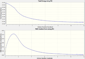 |
It is clear by computing at 200 points is more reliable becuase a minimum energy is given that is similar to the Gauche 5 confomer as seen in Appendix 1. It is now clear conformer the transition state proceeds through.
Calculating the activation energies
The activation energies were calculated for the rearrangement that proceeds via both transition states of different structures. For this, using the B3LYP/6-31G* level of theory will be used to reoptimise the transition structures that were initially optimised using HF/3-21G theory. A frequency analysis was also taken to confirm that they are the minimum energy geometries. The results of these optimisations are shown below (Table 8):
| HF/ 3-21G | B3LYP/ 6-31G* | |||||
|---|---|---|---|---|---|---|
| Electronic Energy | Sum of electronic and zero point energies (0 K) |
Sum of electronic and thermal energies (298.15 K) |
Electronic Energy | Sum of electronic and zero point energies (0 K) |
Sum of electronic and thermal energies (298.15 K) | |
| Chair TS | -231.61932217 | -234.2099848 | -231.466700 | -234.50542677 | -234.36260777 | -234.362607 |
| Boat TS | -231.60280049 | -231.450921 | -231.445287 | |||
| Reactant (Anti:2) | -231.69254 | -231.539545 | -231.539541 | -234.55970439 | -234.416245 | -234.416245 |
Using this, the activation energies were then calculated. This was done by calculating the differences in electronic energy. At 0 K, the values for the sum of electronic and zero point energies for the Anti:2 conformer and both transition structures were subtracted from each other. At 298.15 K, the sums of electronic and thermal energies were subtracted from each other. These values are compared to experimental values as shown below in Table 9:
| B3LYP/ 6-31G | Experiment | ||
|---|---|---|---|
| 0 K /a.u. (kcal mol-1) | 298.15 K/ a.u. (kcal mol-1) | 0 K/ kcal mol-1 | |
| Act. energy(chair) | 0.0545 (34.05) | 0.05242 (33.15) | 33.5±05 |
| Act.energy (boat) | 0.0654 (41.96) | 0.06765 (42.22) | 44.7±2.0 |
The table shows that the chair transition structure has a smaller activation energy compared to the boat transition structure. This is correct because the chair conformer has less steric strain. This confirms that the reaction will kinetically proceed through a chair transition state. Furthermore, the values given from the higher level of theory for chair structure are very similar to experimental values. The difference can be accounted for simple systematic errors in both values. The boat transition structure is not as similar to the experimental value but is still relatively close. It is also noted that as the temperature increases, the activation energy becomes smaller, which is expected.
Conclusion
In conclusion, the gauche:3 conformer is the most stable reactant as the lowest energy was calculated for this molecule. The chair transition state was calculated to be the most stable transition structure in comparison to the boat geometry. This was calculated using B3LYP/6-31G and HF/31-G levels of theory; the former being more accurate. However both were used to compare them and so that the higher level of theory would take less time when an initial optimisation was taken using HF/31-G.
The Diels Alder Cycloaddition
Background
The Diels Alder reaction is a pericyclic reaction that occurs in a concerted manner. That is, the reaction mechanism has one step and can be seen below:

The pi orbitals of the dieneophile and the pi orbital of the diene overlap and form new sigma bonds. This reaction is only allowed when the HOMO of one fragment significantly overlaps the LUMO of the other fragment which has the correct symmetry. Otherwise, the reaction is forbidden. Also, a substituted dieneophile can sometimes stabilise the regiochemistry when the new pi orbitals interact with the double formed in the product.
In the following investigation, the Diels Alder reaction will be studied by finding the transition structure using quantum mechanical methods. A substituted dieneophile will be studied by analysing the reaction of Cyclohexa-1,3-diene with Maleic Anhydride.
Diels Alder reaction: Butadiene and ethylene
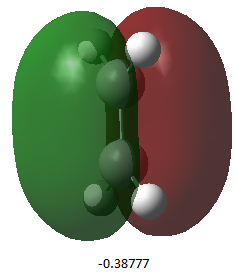
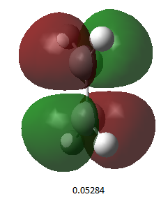
The AM1 level of theory was used to optimise both the cis-butadiene and ethylene molecules. The HOMO’s and LUMO’S of each molecule determine whether the reaction will be disallowed or allowed. They were therefore analysed and can be seen below:
| Butadiene Media:rksCISBUTADIENEOPT.LOG | Ethylene Media:rksETHENEOPT.LOG | |
| HOMO (energy /a.u.) |  |
|
| Symmetry | antisymmetric | symmetric |
| LUMO (energy /a.u.) | 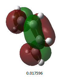 |
|
| Symmetry | symmetric | antisymmetric |
The table shows that there the HOMO’s include pi orbitals that overlap constructively ( π orbitals), whilst the LUMO’s include pi orbitals that overlap deconstructively (π* orbitals). Analysing the symmetry of the MO’s, it can be seen that the cis-butadiene LUMO can interact with the ethylene HOMO since they have both the same symmetry. Furthermore, the cis-butadiene HOMO can interact with ethylene LUMO.
Transition structure: Frozen co-ordinate method
The transition structure was calculated using the frozen coordinate method. For this, the bonds formed (C-C) were frozen at 2.1 angstroms. The semi-empirical AM1 theory was still used, and then B3LYP/6-31G was used to optimise the molecule to a higher accuracy. Initially, the TS(Berny) theory was used but this was unsuccessful and a transition structure was not found. Also, the QST(2) method was used but this was found to be taking extremely long (especially with the atom labelling) and was therefore abandoned. The results for this can be seen below (Table 11):
| Jmol |
| |||
| Link | Media:rksDIELS631.out | |||
| Energy (a.u.) | -234.49456053 | |||
| Imaginary Frequency (cm-1) | -534 | |||
| Imag. Frequency simulation | 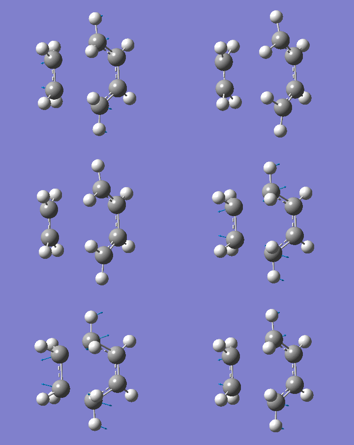
| |||
| C-C bond forming length (Å) | 2.26 | |||
| C=C bond length in ethylene (Å) | 1.39 | |||
| C=C lengths in cis-butadiene (Å) | 1.39 | |||
| C-C single bond length Lit. value (Å) [2] [3] | 1.54 | |||
| Carbon van der waals radius Lit. value (Å) [2] [3] | 1.70 | |||
| C-C double bond length Lit. value (Å) [2] [3] | 1.34 |
It was observed that the length of the bond formed (being formed) when using the AM1 was much shorter than the final optimised geometry when using the B3LYP method. Along with this, the imaginary frequency was also different. This indicates that a different transition structure was calculated for each. However, the correct transition state was found using B3YLP because a minimum energy was found. In addition, the imaginary frequency indicates that that the formation of the bonds is concerted and synchronous. But, the lowest real frequency is asynchronous which corresponds to the rotation of the ethylene.
When comparing data to the literature values (see above table), it is evident that the computational bond forming length is considerably larger that the C-C single bond literature value. However, it is smaller the addition of two Van der Waals radii of carbon and hence suggesting that there is some form of bonding occurring. The double bonds on both ethylene and cis-butadiene are also longer than the reported value for a double bond. This indicates that these bonds are becoming more of a single bond.
MO’s of the transition state
The HOMO and LUMO were both examined for the transition state and can be seen in Table 12 below:
| HOMO | 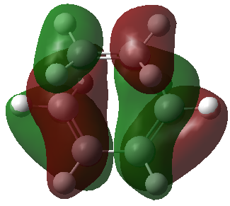
|
|---|---|
| Energy (a.u.) | 0.02315 |
| Symmetry | antisymmetric |
| LUMO | 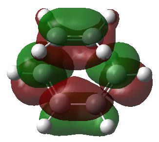
|
| Energy (a.u.) | -0.32394 |
| Symmetry | symmetric |
Only orbitals of the same symmetry can overlap and form a new bond. The new bonds form supraficially through a Huckel transition state. The HOMO consists of the cis-butadiene HOMO and the ethylene LUMO. These two orbitals have the same symmetry and will form two new C-C σ bonds. The LUMO consists of the cis-butadiene LUMO and the ethylene HOMO to form two new C-C σ* orbitals.
Cyclohexa-1,3-diene with maleic anhydride
The reaction between cyclohexa-1,3-diene and maleic anhydride has been extensively studied in literature and it has been confirmed that the endo product is the major (kinetic) product. This result, along with the transition states, will be investigated computationally. This may give information on how the pi bonds from the substituents on the dienophile interact with other pi bonds to control the regiochemistry. The two products yielded from this reaction are shown below:

Optimisations of the transition structures
Two transition states were optimised for the endo and exo products. The frozen coordinate method was used because from previous experience, this method seemed to be the most accurate and the least time consuming. This method entailed freezing the bond formed at 2.2 Å, optimising to a minimum using the semi-empirical/AM1 method, unfreezing the distance for the bond formed and reoptimising to the transition structures using B3LYP/ 6-31G* level of theory. An initial guess at the structures were obtained by simply placing one molecule on top of the other as it is known that the mechanism occurs through p orbital overlap, and the p orbitals exist above and below the plane of the molecule. Table 13 shows the results:
| Exo | Endo | |||||||
|---|---|---|---|---|---|---|---|---|
| Structure |
|
| ||||||
| Energy (a.u.) | -0.05050322 | -0.05159429 | ||||||
| C-C bond forming distance (Å) | 2.17 | 2.16 | ||||||
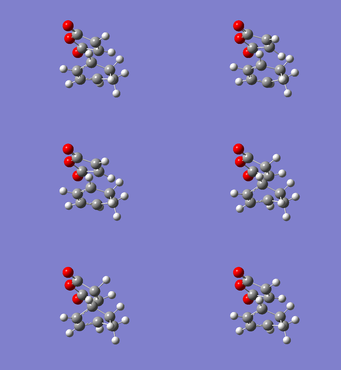
| Imaginary frequency (cm-1) | -810 | -806 | ||||||
| Imaginary frequency animation | 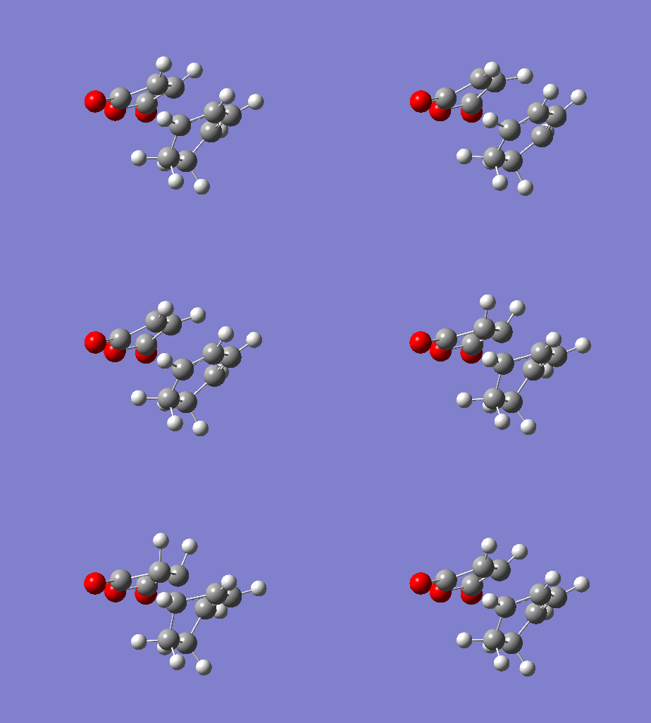 |
|
The imaginary frequencies show that the reaction occurs in a concerted fashion but the value is lower for the endo product. This signifies that the endo product has a lower energy reaction pathway which correlates with the lower calculated energy for the endo transition structure. Furthermore, the exo product has a larger bond forming length than the endo product. This indicates that the endo product is more likely to be formed because there will be better orbital overlap and the overall bond energy will lie lower down on the Lennard potential curve.
Analysing the bond distances and atom distance between molecules can provide some useful information. Firstly, it was noted that the C=C bond which is becoming a C-C bond has a bond length that is intermediate of both distances. This intermediate value can also be seen with the single C-C bond that is transforming to a C=C bond. The difference in stabilising energies of the two states can be understood by investigating the atom distances. It was seen that the exo state has less steric strain because the distance between the anhydride carbon and opposite carbon atom on the other molecule is larger. Therefore, the electron clouds will overlap less and there will be reduced repulsion. This does not however explain the ordering of the energies given in Table 13. This ordering can be explained by considering the secondary orbital effect. This is shown schematically below:
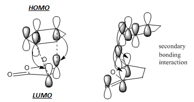
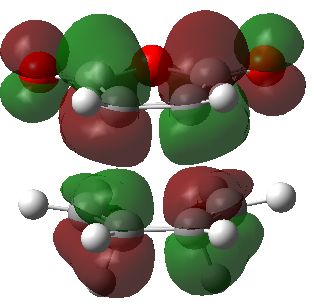
For the endo transition structure, there is an interaction between the p orbitals of anhydride carbonyl carbon atoms and the p orbitals from the diene. This interaction is stabilising as the orbital symmetries are in phase. This stabilising interaction does not occur in the exo structure and as a result, the exo structure is higher in energy. In this case, the secondary orbital effect is the overriding factor determining the relative energies of both transition states. Overall, this makes the endo product the kinetic product.
MO’s of the transition states
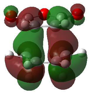
The secondary orbital overlap can be rationalised by studying the frontier molecular orbitals involved in the reaction. These are shown below (Table 15):
| Endo product | Exo product | |
|---|---|---|
| HOMO | 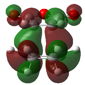 |
|
| Energy (a.u.) | -0.34507 | -0.34275 |
| Symmetry | Antisymmetric | Antisymmetric |
| LUMO | 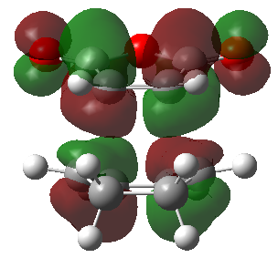 |
|
| Energy | -0.03569 | -0.04043 |
| Symmetry | Antisymmetric | antisymmetric |
Conclusion
In conclusion, the transitions structures of various compounds were determined using computational methods. This was then used to investigate the reaction pathway and therefore the kinetic product by finding the transition state with minimum energy. Along with this, activation energies could be calculated and therefore stresses the importance of computational methods in recent times to analyse weather a reaction will be favourable or not. Furthermore, computational techniques were successfully used to calculate allowed and disallowed reactions using orbital symmetries. Throughout the experiment, it was noted that many calculated values were in strong agreement to literature values (taking into account systematic error) signifying the investigation was completed effectively.
References
- ↑ G. Schultz and Istvfin Hargittai, Journal of Molecular Structure, Volume 346, 15 February 1995, Pages 63-69, Electron Diffraction and Structural Chemistry doi:10.1016/0022-2860(94)09007-C
- ↑ 2.0 2.1 2.2 Martinez-Guajardo G, Donald KJ, Wittmaack BK, Merino G (2010). "Shorter Still: Compresing C-C Single Bonds". Organic Letters, ASAP
- ↑ 3.0 3.1 3.2 Fox, MA and JK Whitesell. Organische Chemie. 1994. Cite error: Invalid
<ref>tag; name "liters1" defined multiple times with different content

