Rep:Mod:2510lm1
Techniques of Molecular Mechanics and Semi-Empirical Molecular Orbital Methods for Structural and Spectroscopic Evaluations
-Layla Malouf
Dicyclopentadiene: Formation and Isomerisation
The dimerisation of cyclopentadiene
At room temperature, cyclopentadiene will undergo a [4+2] cycloaddition reaction with itself to form two isomers of dicyclopentadiene (DCPD), endo- and exo-, as shown in figures 1 and 2. In order to see which isomer has the preferred configuration, they were both visualised in the programme ChemBio3D, and their geometries optimised using the Allinger Molecular Mechanics 2 (MM2) force field to find the minimum energies of the two isomers.


| Property/ kcalmol-1 | endo- dimer | exo- dimer | Energy difference |
| Stretch | 1.2511 | 1.2851 | -0.0340 |
| Bend | 20.8484 | 20.5794 | 0.2690 |
| Stretch-Bend | -0.8359 | -0.8379 | 0.0020 |
| Torsion | 9.5106 | 7.6555 | 1.8551 |
| Non-1,4 VDW | -1.5432 | -1.4158 | -0.1274 |
| 1,4 VDW | 4.3190 | 4.2326 | 0.0864 |
| Dipole/Dipole | 0.4475 | 0.3775 | 0.0700 |
| Total Energy | 33.9975 | 31.8765 | 2.1210 |
Semihydrogenation of DCPD
|
Hydrogenating a DCPD molecule is a stepwise process. Initially, only one double bond reacts (at a high rate) to form the dihydro- product, and as this process comes to an end the second double bond begins to react but at a much slower rate than the first. [1] This means that again, two isomers can be formed from the selective, incomplete hydrogenation of DCPD, each with their uses in industry. [2]
Both dihydro- products are attached as .jmol images. Hydrogenation product A is shown first, hydrogenation product B is below it.
|
| Property/ kcalmol-1 | Product A | Product B | Energy difference |
| Stretch | 1.2783 | 1.0964 | 0.1819 |
| Bend | 19.8615 | 14.5229 | 5.3386 |
| Stretch-Bend | -0.8346 | -0.5492 | -0.2854 |
| Torsion | 10.8088 | 12.4979 | -1.6891 |
| Non-1,4 VDW | -1.2233 | -1.0688 | -0.1545 |
| 1,4 VDW | 5.6322 | 4.5123 | 1.1199 |
| Dipole/Dipole | 0.1621 | 0.1406 | 0.0215 |
| Total Energy | 35.6850 | 31.1520 | 4.5330 |
Discussion
Using the MM2 forcefield, we found that the energies of the two dimers differ by 2.121kcal/mol (identical to the relative energies reported in literature.[3] using the same method and basis set), with the exo- product being more stable. This should mean that the exo- product is formed preferentially in the dimerisation reaction, however this is not true. At low temperatures it has been found that the dimerisation of cyclopentadiene leads, almost exclusively, to the formation of the endo- isomer.[3] As the temperature is raised, a preference towards the formation of the exo- isomer is seen, and furthermore, the it was found that the exo- isomer does not, at high temperatures, dissociate back into the cyclopentadiene monomers; to do so the exo- isomer must convert into the endo- dimer, which can then dissociate.[4] This indicates that at low temperatures, the dimerisation of cyclopentadiene is under kinetic control- forming endo-DCPD goes through a more stable transition state than forming exo-DCPD, and so the reaction occurs at a faster rate. When the temperature is raised, thermodynamic effects come into play and the more stable dimer is formed, explaining why the exo- product only starts becoming favoured at ~180-240°C.
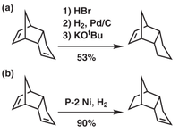
The two hydrogenation products can be produced as shown in figure 3. Product B is formed easily, using the standard catalytic hydrogenation approach and giving a high yield. Product A is more difficult to produce- the strained alkene in the norbornene ring has to be masked by hydrobromination, the other alkene is then hydrogenated and then HBr is eliminated to produce the desired product[5]. This is more difficult to do and leads to a lower yield (53% compared to 90%) due to the preference of hydrogenating the norbornene alkene. This can be seen in the energy calculations of the two products- isomer B is ~4.5kcal/mol more stable than isomer A, where the biggest contribution comes from the bending energies- that of B is ~5.3kcal/mol more stable than A. Clearly, the relief of the strained alkene in the norbornene ring is the cause of the large energy difference; hydrogenating it leads to a significant fall in the molecule's energy.
Atropisomerism in an Intermediate in the Synthesis of Taxol
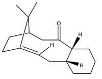
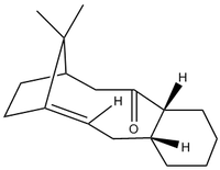
The intermediate has two isomers, one in which the ketone is pointing "up" and the other in which the ketone points "down". This is an example of atropisomerism, where the carbonyl group cannot easily rotate about the C-C single bond because of the high steric strain caused by the rest of the molecule. A comparison of the two molecules was carried out using the same methods as before: optimising using the MM2 force field.
| Property/ kcalmol-1 | Isomer 1 | Isomer 2 | Energy difference |
| Stretch | 2.7847 | 2.6379 | 0.1468 |
| Bend | 16.5405 | 12.5572 | 3.9833 |
| Stretch-Bend | 0.4298 | 0.4253 | 0.0045 |
| Torsion | 18.2550 | 19.1224 | -0.8674 |
| Non-1,4 VDW | -1.5530 | -1.6113 | 0.0583 |
| 1,4 VDW | 13.1074 | 12.8590 | 0.2484 |
| Dipole/Dipole | -1.7249 | -1.7019 | -0.0230 |
| Total Energy | 47.8396 | 44.2887 | 3.5509 |
Discussion
| Isomer 1 | Isomer 2 | ||||||
|
|
The cyclohexane ring in each molecule is in a different chair conformation in each molecule- the interconversion between one chair form and the other is what causes the position of the carbonyl to change from "up" to "down". With enough time, the interconversion between the two atropisomers leads to the formation of the most favoured isomer; the one with the lowest energy. There is an energy difference of ~3.6kcal/mol between the two, with Isomer 2 (ketone pointing down) being lower in energy and therefore the most stable.
To check this, a further minimisation calculation was run using the molecular mechanics MMFF94 force field:
| Property/ kcalmol-1 | Isomer 1 | Isomer 2 | Energy difference |
| Final energy | 70.5398 | 63.2778 | 7.2620 |
Again, isomer 2 is more stable, this time by ~7.3kcal/mol. This confirms that all of the "up" isomer should convert to the "down" isomer, but in reality this occurs very slowly. This is probably due to the high energy needed to flip the highly substituted cyclohexane ring.
Regioselective addition of dicholorocarbene to a diene
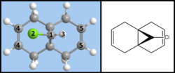
It was found[6] that when reacting the diene pictured in figure 7 with an electrophilic reagent such as a dichlorocarbene, the reaction is stereospecific and produces the product shown below:

This is the only product formed from the cycloaddition of a dichlorocarbene to this diene, and in fact, the alkene close to the Cl-C bond is so reactive that the only way to selectively add a dichlorocarbene to the other alkene group is to protect the reactive alkene by adding m-CPBA and forming a protecting epoxide functional group. The other alkene can then react, after which the epoxide is removed using AlI2.[6]
To find out why the reaction regioselective, the diene was optimised using two different methods, the MM2 Force Field and the MOPAC Interface (method set to RM1). This naturally led to different physical and chemical properties being reported, as summarised below. The two outputs are also linked here: link for MM2-optimised file and link for Mopac-optimised file.
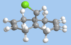
As well as the main data summary, a way of easily visualising the difference between the two methods of optimising is to look at an "overlay" of the structures produced by each method (figure 8). Minimising the energy using the MOPAC interface produces a more accurate view of the structure as it includes in its calculations a treatment of the wave-description of electrons; the quantum mechanical approach is therefore more comprehensive than the purely mechanical MM2 approach (which does still have its uses).
| Property | MM2-optimised | MOPAC RM1-Optimised |
| Energy/ kcalmol-1 | 17.895 | 22.828 |
| Distance: C1-C4 | 3.22Å | 3.09Å |
| Distance: C1-C5 | 2.98Å | 2.92Å |
| Bond Distance: Cl (2)-C4 | 3.11Å | 2.928Å |
| Bond Distance: H (3)-C5 | 2.80Å | 2.71Å |
The formation of the endo- isomer is easily explained: the CCl2 adds to the ring in such a way to avoid the steric interactions that would occur between the CHCl bridge and the dichlorocarbene if an exo- addition took place. Explaining why the dichlorocarbene adds across one double bond and not the other requires an examination of the MOs. To do this, the MOPAC RM1-optimised structure was used in a calculation involving the advanced mode in the MOPAC interface. The MOs were then invoked and visualised, with the HOMO-1, HOMO, LUMO, LUMO+1 and LUMO+2 orbitals shown below:
| Orbital Type | Image | Energy/eV |
| HOMO-1 | 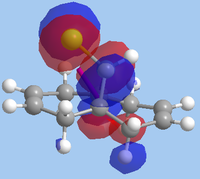 |
-10.901 |
| HOMO |  |
-10.406 |
| LUMO |  |
0.966 |
| LUMO+1 | 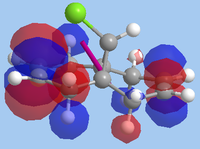 |
1.401 |
| LUMO+2 | 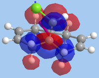 |
15.113 |
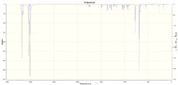
Furthermore, a frequency analysis was carried out on the MOPAC RM1-optimised structure. This was done by subjecting the molecule to a B3LYP/6-31G(d,p) optimisation and frequency, restricting the point group to Cs and running the calculation on the SCAN HPC system, and the results can be accessed here: DOI:10042/22210 .
The mechanism of glycosidation
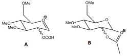
Glycosidation reactions are very common in nature, where a glycosidic bond (a bond between the anomeric carbon of a sugar molecule and another molecule) is formed. In these reactions, the final product can either be the α-anomer (where the nucleophilic reagent is in the axial position) or the β-anomer (where it is in the less hindered equatorial position). Both tend to be formed, but there is some preference towards the α-anomer, especially if the reaction proceeds under thermodynamic control. The glycosidation reaction goes through two intermediates, A and B, pictured in figure 9. The acetyl group can be in different configurations, and it is this group which determines which anomer is ultimately favoured through the neighbouring group interaction effect. Each intermediate has four isomers, and each of these were modelled and their energies found using the MM2 force-field and the MOPAC PM6 interface.
Intermediate A
| Property | Isomer A1 | Isomer A2 | Isomer A3 | Isomer A4 | ||||||||||||
| Image (MM2 optimised structure) |
|
|
|
| ||||||||||||
| MOPAC PM6 structure | Isomer A1 | Isomer A2 | Isomer A3 | Isomer A4 | ||||||||||||
| MM2 Energy/ kcalmol-1 | 20.9884 | 39.4962 | 27.8709 | 19.9017 | ||||||||||||
| MOPAC PM6 Energy/ kcalmol-1 | -87.99417 | -82.09688 | -91.57959 | -91.58011 | ||||||||||||
| Distance from Ocarbonyl to Coxenium/ nm (MM2) | 0.256 | 0.408 | 0.298 | 0.259 | ||||||||||||
| Distance from Ocarbonyl to Coxenium/ nm (MOPAC PM6) | 0.161 | 0.418 | 0.155 | 0.155 |
Isomers A1 and A2 are those in which the acetyl group is in the axial position, pointing towards (A1) or away from (A2) the ring. Between these two axial isomers, there is an energy difference of ~18.5kcal/mol in favour of the A1. This is because the interaction between the carbonyl oxygen and the oxenium carbon is favourable, providing an energy stabilisation of the molecule. For A1, this interaction can occur easily because of the short distance between the two (0.256nm), whereas in A2 the two atoms are too far apart to interact. This effect is also seen in the PM6-optimisation, where A1 is ~5.9kcal/mol more stable than B1 and the distance between the two atoms in question has increased in isomer A2. Clearly, the acetyl group will determine what the final product will look like.
Isomer A3 and A4 are those in which the acetyl group is in the equatorial position, pointing either at the "top face" (A3) or the "bottom face" (A4) of the ring. Between these isomers, there is an energy difference of ~8.0kcal/mol in favour of isomer A4. Again, the interaction of the carbonyl O and the highly electrophilic oxenium C leads to a stabilisation- in A4 the carbonyl is closer to the carbon and there is a better orbital overlap between the two.
Intermediate B
This is when intermediate A reacts within itself to form a more stable 5-membered ring.
| Property | Isomer B1 | Isomer B2 | Isomer B3 | Isomer B4 | ||||||||||||
| Image (MM2 optimised structure) |
|
|
|
| ||||||||||||
| MOPAC PM6 structure | Isomer B1 | Isomer B2 | Isomer B3 | Isomer B3 | ||||||||||||
| MM2 Energy/ kcalmol-1 | 31.1349 | 27.3618 | 43.4560 | 44.7661 | ||||||||||||
| MOPAC PM6 Energy/ kcalmol-1 | -88.52858 | -91.66108 | -65.46105 | -66.88183 |
Isomers B1 and B2 are those where the ring has formed on the same face, leaving the two hydrogens in the cis- position. B3 and B4 are the two isomers where the hydrogens are trans- to each other, and it can be seen from both the MM2 and MOPAC PM6 energies that B1 and B2 are favoured. Overall, isomer B2 is the most stable, being ~3.8kcal/mol lower in energy than B1. This is due to the distance between the oxenium carbon and the methoxy oxygen (as seen in the .jmol image) being a lot shorter for B2, so there is a good overlap between the lone pairs on the oxygen and the electrophilic carbon, leading to a stabilisation of the overall energy.
Overall, the models explain the trans-selectivity of glycosidation reactions by the fact that in both intermediate steps, the intermediates which lead to the β-anomer are higher in energy and therefore less likely to form.
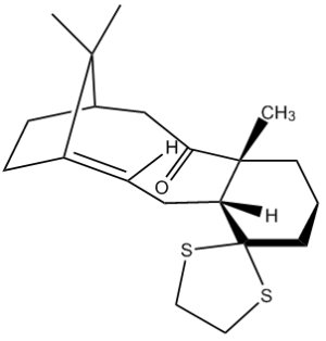
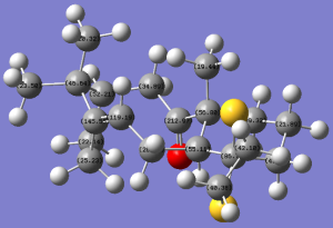
Figure 10 shows another intermediate related to the synthesis of taxol. This, like the one mentioned previously, is one of two atropisomers formed, where the other isomer has the ketone group pointing "up".
This isomer was modelled using ChemBio3D, its energy minimised using the MM2 force field and then again using the Gaussian interface, method set to DFT B3LYP and basis set 6-31G(d,p). The solvation model was also chosen based on what a literature[7] experiment has already chosen, in this case <chemform>C6D6</chemform> for ease of comparison. This produced the following 13C NMR spectrum and data, attached here, and all calculation files are also accessible here: DOI:10042/22245 .
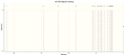
The calculated NMR spectrum shows decent agreement with literature values [7], as seen below (for carbon labeling please see figure 11):
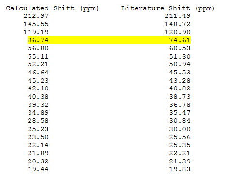
The biggest discrepancy is highlighted in yellow, where there is a difference of 12.13ppm between the reported shifts and the computed ones. This is at the carbon attached to the dithiane group and is due to the fact that it's bonded to the heavy S atoms. The large spin-orbit coupling effects caused by the C-S bond tends to lead to a difference in the computed and experimental data, as reported in some [places].
Overall, however, using computational techniques to confirm predicted structures is very useful and mostly accurate.
Mini-Project: A study of the reaction between iodonium ylides and diphenylketene
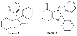
A reaction recently reported in literature[8] was chosen in this project, where the electrophilic of an iodonium ylide with a diphenylketene led to the formation of two ismoeric products, pictured in figure 12. For the sake of clarity, the original literature labelling has been kept in this report.
Isomer 3
Structure drawn in ChemBio3D, optimised first using MM2 then again using the MOPAC interface, PM6 method. This produced a structure where the 5-membered ring appeared more planar. Energy calculated using PM6 method: -53.53097, total energy calculated using MM2 force field: 17.407 kcal/mol. This was then optimised using the Gaussian interface, using the DFT=mpw1pw91 method, and keeping with the 6-31G(d,p) basis set. The job was submitted to the SCAN HPC service, and the results for the optimisation can be found here: DOI:10042/22248 .
Once this was completed, the 1H and 13C NMR spectra were predicted in a similar way as before, this time specifying <chemform>CDCl3</chemform> as the solvent, in accordance with literature, and using the same method (mpw1pw91) and basis set. The output files can be accessed here: DOI:10042/22249 .
Attached are the 1H and 13C NMR spectra, along with the chemical shift summaries (1H and 13C
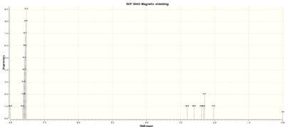
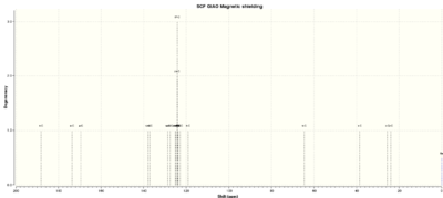
The difference between literature can be seen directly in figure 13 (not shown are the Ph groups for brevity).
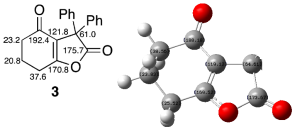
Overall, there is a very good agreement between the two, although there is a very large difference (15.36ppm) between the two reported values for the carbon next to the carbonyl group- this is an error typical of calculating NMR spectra using computational methods, and therefore is not too big of a problem.
The IR spectrum of this isomer was also calculated, attached here:
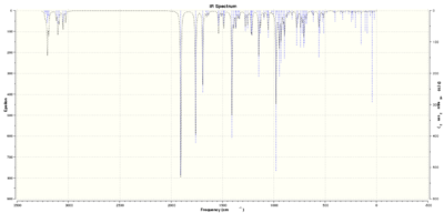
Literature values for IR stretches do not seem to fully agree with computed results- more frequencies (of not insignificant intensities) are reported in the calculated results than in literature, for unknown reasons.
Isomer 5
The isomer was modelled and initially optimised using the same methods as for isomer 3, yielding the following energies (in kcal/mol):
MM2 energy: 24.2560, MOPAC PM6: -50.70261.
However, when the molecule was submitted to the SCAN HPC service to optimise using the Gaussian interface, the job failed. Attached is the a diagram showing the energy of the molecule at each optimisation step:

It was assumed that the reason for the failure was an insufficient number of cycles run, so the job was re-run allowing 60 cycles and 100 cycles. Both failed, and the data can be accessed here: 60 cycle failure: DOI:10042/22258 , 100 cycle failure: DOI:10042/22259 .
The input file was submitted again, this time with no limits placed to allow the job to run to completion. At the time of writing, the job had not finished running.
Notes and References
- ↑ T. N. Antonova, I. A. Abramov, V. Sh. Feldblyum, I. G. Abramov, A. S. Danilova, "Catalytic hydrogenation of dicyclopentadiene to dicyclopentene in the liquid phase", Pet. Chem., 2009, 5, 366-368: DOI:10.1134/S0965544109050041
- ↑ D. Skála, J. Hanika, "Kinetics of dicyclopentadiene hydrogenation using Pd/C catalyst", Petroleum and Coal, 2003, 45, 105-108. Accessible [[1]] as DOI numbers not available for this journal
- ↑ 3.0 3.1 M. E. Jamróz, S. Gałka, J. C. Dobrowolski, "On dicyclopentadiene isomers", J. Mol. Struct., 2003, 634, 225-233: DOI:10.1016/S0166-1280(03)00348-8
- ↑ J. E. Baldwin, "Cycloadditions. IX. Mechanism of the Thermal Interconversion of exo- and endo-Dicyclopentadiene", J. Org. Chem., 1966, 31, 2441-2444: DOI:10.1021/jo01346a003
- ↑ 5.0 5.1 T. J. A. Graham, T. H. Poole, C. N. Reese, B. C. Goess, "Regioselective semihydrogenation of dienes", J. Org. Chem., 2011, 76, 4132-4138: DOI:10.1021/jo200262r
- ↑ 6.0 6.1 B. Halton, S. G. G. Russell, ".pi.-Selective dichlorocyclopropanation and epoxidation of 9-chloro-1,4,5,8-tetrahydro-4a,6a-methanonaphthalene. Controlled synthesis of the C-9 epimers of (1a.alpha.,2a.alpha.,6a.alpha.,7a.alpha.)-1,8,8-trichloro-1a,2,3,6,7,7a-hexahydro-2a,6a-methanocyclopropa[b]naphthalene", J. Org. Chem., 1991, 56, 5553-5556: DOI:10.1021/jo00019a015
- ↑ 7.0 7.1 L. Paquette, N. A. Pegg, D. Toops, G. D. Maynard, R. D. Rogers, "[3,3] Sigmatropy within 1- Vinyl-2-alkenyl-7,7-dimethyl-exo-norbornan-2-ols. The First Atropselective Oxyanionic Cope Rearrangement", J. Am. Chem. Soc., 1990, 112, 277-283: DOI:10.1021/ja00157a043
- ↑ A. Antos, Y. Elemes, A. Michaelides, J. A. Nyxas, S. Skoulika, L. P. Hadjiarapoglou, "The Question of Electrophilic vs Nucleophilic Addition of Cyclic β‑Dicarbonyl Phenyliodonium Ylides: Electrophilic Cycloaddition of Diphenylketene", J. Org. Chem., '2012, 77, 10949-10954: DOI:10.1021/jo3020787
