Rep:Mod3ps3712
INTRODUCTION
The aim of the computational exercises were to learn, understand and characterise the transition states (TS) and Potential Energy Surfaces (PES) of both the Cope Rearrangement as well as the Diels Alder Cycloaddition. The key difference in this computational exercise as to the one carried out previously is that there was no fitted formula used as the formulas are unable to describe the breaking and forming of the bonds and the changes in type of bonds. In order to overcome this, a molecular based method which involves numerically solving the Schrodinger Equation is used. This allows the calculation of the reaction path and the barrier height as well as the visualisation of the transition structure.
COPE REARRANGEMENT
In this tutorial, the Cope Rearrangement as shown above is used in order to locate the energy minima as well as the transition structures on the C6H10 potential energy surface which was then used to determine the preferred reaction mechanism
Figure 1: The Cope Rearrangement [1]
This rearrangement is an example of a [3-3] sigma tropic shift rearrangement. The reaction mechanism (concerted, stepwise or dissociative) for this rearrangement has been a topic of discussion for a very long time though it had been accepted that the reaction proceeds by a concerted mechanism via either a ‘boat’ or a ‘chair’ transition structure. The boat transition structure is reported to be that of a higher energy in comparison with the chair confirmation. The Gaussian calculation was used in order to show that is true.
Optimising Reactant and Product
The different conformations of the 1,5-hexadiene molecules were drawn on GaussView and these structures were optimised using the basis set HF/3-21G. Once optimisation was complete, the point groups and the potential energies were used in order to compare it with experimental values.
1,5-hexadiene with Anti-linkage
The first conformation that was constructed was that with an anti- conformation in which the two terminal carbons were relatively far away from one another. The structure was then optimised using the basis set as mentioned before and produced an energy of -231.69254 a.u as well as a point group of Ci. When the results were compared with data from appendix one, it was noted that the structure obtained corresponds to that of Anti 2.
Figure 2: Structure of 1,5 hexadiene after minimisation
1,5-hexadiene with Gauche-linkage
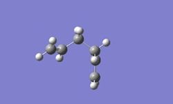
The second confirmation that was constructed had a gauche confirmation in which the carbons were closer to one another. The structure was also optimised using the basis set HF/3-21G and had an energy of -231.69266 a.u and a point group of C1. Comparisons with data from appendix one showed that the structure that was obtained corresponds to that of Gauche 3.
Figure 3: Structure of 1,5 hexadiene in gauche conformation
In theory, it was expected that the conformation with the anti-linkage have a lower energy as steric repulsion are largely reduced due to the periplanar positions of the carbons groups. .Comparison of both the gauche and anti-conformer show that Gauche 3 in fact have a slightly lower energy value. Hence this indicates that steric factors are not the only contributing factor to the energy value. The overlapping of the molecular orbitals as well as the hyperconjucation effect affects the value of the energy hence giving the Gauche Conformation a lower energy.
Optimisation of C2 Anti- Structure
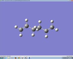
The C2 Anti- Structure was used as the reactant for the cope rearrangement above. As the structure was already located previously in earlier parts, the structure was then optimised using B3LYP/6-31G*. The structure obtained is shown as below. The point group of this structure was also Ci with an energy of -234.571 a.u. There was no noticeable change in the overall geometry of the structure even though there was a slight decrease in energy for the structure using the higher theory calculation.
Figure 4: Structure of 1,5 hexadiene in anti conformation
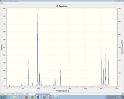
The structure obtained from the second optimisation was then used to carry out a frequency calculation at the same level of theory. When checked, the structure did not produce an imaginary vibrational frequency hence indicating that the structure has indeed be minimised.
Figure 5: IR spectrum of minimised structure of C2 anti- conformation
The table below shows the thermochemistry data of the vibrational frequencies.
| TYPE OF ENERGY | Energy at 298K using B3LYP/6-31G* | Energy at 0.01K using B3LYP/6-31G* |
|---|---|---|
| Sum of electronic and zero-point energies | -234.428 | -234.428 |
| Sum of electronic and thermal energies | -234.421 | -234.428 |
| Sum of electronic and thermal enthalpies | -234.419 | -234.428 |
| Sum of electronic and thermal free energies | -234.459 | -234.428 |
At a much lower temperature, the value of the energies of each of the calculation equate to the Sum of electronic and zero point energies as well as the sum of electronic and thermal energies.
OPTIMISING “CHAIR” AND “BOAT” TRANSITION STRUCTURES
In theory, it is known that there are two possible transition structures, ‘chair’ and ‘boat’ in which the reaction proceeds by. These transition structures are optimised using three different methods which will be discussed in the section below. The energies of these transition structures are obtained via these calculations and are compared in order to show which transition structures the reaction actually proceeds through. The Intrinsic Reaction Coordinate along with the activation energy of the Cope Rearrangement was also calculated in this exercise.
Drawing of Allyl Fragment
An allyl fragment of C3H5 was drawn with and optimised using the HF/3-21G theory and the structure below was obtained. When comparisons were made, it looked similar to half of what the predicted chair transition structure would look like.
Figure 6: Structure of optimised allyl fragment
The optimised structure was then used to build the chair transition state by copying the allyl fragment and orientating the fragments. The distance between the two terminal carbons were approximately 2.2Å apart. This structure shown below was used as the guess chair transition structure.
Figure 7: Structure of Chair Transition State
TS Berny Method
The first method used involved the optimisation of the Guess Chair Transition structure to a minimum energy level using a TS (Berny) method. The default basis set that was used in this calculations were HF/3-21G. The force constant was also calculated once along and in order to prevent the calculation from crashing when more than one imaginary frequency vibration is detected, Opt=NoEigen is added into the calculation. The structure below shows the optimised chair transition structure obtained from the method described above. There was only one imaginary frequency vibration as expected at -817.92.
Figure 8: Structure of Optimised Chair Transition State
Freeze Coordinate Method
Optimisation of the transition structure using this method involves fixing the distance between the two sets of terminal carbons where the bond is expected to form/break at 2.2Å. The structure obtained was very similar to that obtained from the TS Berny Method.This structure was then used to obtain the optimised Chair transition structure using a TS Berny method. By using the basis set HF/3-21G the approach taken for this calculation was similar but instead of calculating the force constant as we did earlier on, a normal guess Hessian method to obtain the required data of the terminal carbons. The structure that was also obtained from this calculation is similar to that in figure 8.
Figure 9: Final Structure of Optimised Chair Transition State
QST2 Optimisation
The Boat transition structure was then found using this method. In this method, both the reactant and product can be specified and the transition state is calculated by interpolating the reaction. The link below indicates the structure of both the reactant and product using the optimised anti-2 structure in which atoms on the molecule were relabelled to from 1 to 16.
Media:Reactant and product.jpg.ogg
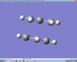
This structure was then used to carry out an Opt+Freq calculation. As expected the job fails and the structure that was formed is largely distorted.
Failed Boat Transition Structure |
Figure 10: Failed Boat Transition Structure
This structure that was formed has a large strain as seen from the figure above that the bonds that are being formed are between terminal carbons on diagonal sides rather than between carbons opposite to one another. Thus it is clear that a boat transition structure would never be obtained by using this particular set of reactants and product. Therefore, the reactant and products are manually altered in order to have a more boat like geometry as shown in the diagram below. This was done by altering the dihedral angle between the four carbons to a 0o and the angle between three carbons (C-C-C) to a 100o as shown in the link below.
A QST2 calculation is carried out again and a boat transition structure is obtained. When the vibrational frequencies were visualised, there was only one imaginary frequency at -840.62. This can be seen in the link below.
Media:Final Boat transition structure2.jpg.ogg
Intrinsic Coordinate Reaction (IRC) Calculation
An intrinsic reaction coordinate is a special type of minimum energy path that connects the reactant, transition state and product. Using the chair transition structure, a 50 step IRC was calculated. It was then discovered that only 44 steps were required for the transition structure to reach a minimised geometry. When using the boat transition structure, a 100 step IRC was calculated as it took 76 steps for the transition structure to reach the minimised geometry. The figures below show the final structure of both the chair and boat transition structure.
Structure of Boat Transition Structure in Final Step |
Structure of Chair Transition Structure in Final Step |
Figure 11: Structure of Boat and Chair Transition Structure in Final Step
The energy of the chair transition structure was at -231.619322 and the energy of the boat transition structure was at -231.602801. From this we can actually see that the energy of the transition structure for the chair is lower than the boat, thus it is more likely that it would proceed via the chair transition state.
Calculation of Activation Energy
The activation energy was calculated by reoptimising the both transition structures obtained previously and computing it using a higher level theory, B3LYP/6-31G*. Once the structures were obtained, a frequency calculation was also carried out. The energy values were then compared to the energy values obtained by using a lower theory level. As expected, the energy value of a chair transition structure is lower than the boat. Hence, this reaction passes through the chair transition state before proceeding with the reaction. The usage of a higher level of theory gives rise to a more accurate energy level of the transition structure.
| TYPE OF ENERGY | Energy of Boat TS at using HF/3-21G | Energy of Boat TS at using B3LYP/6-31G* | Energy of Chair TS at using HF/3-21G | Energy of Chair TS at using B3LYP/6-31G* |
|---|---|---|---|---|
| Transition State Energy | -231.60 | -234.50 | -231.62 | -234.60 |
DIELS ALDER CYCLOADDITION
The Diels Alder Cycloaddition is a type of pericyclic reaction which generally involves a diene and a dienophile. Based on the frontier orbital theory, the chemistry of this reaction is largely governed by the interaction between the HOMO and the LUMO of the π orbitals in both the reactants present. The π orbitals of the dienophile generally form a new σ bond upon interaction with the π orbitals of the diene. The formation of these new σ bonds are also the driving force of the reaction to take place.As to how favoured the reaction would be is largely dependent on how well the overlapping of the orbitals are which is governed by symmetry of the LUMO and HOMO involved. When the symmetry of both the HUMO and LUMO are similar then the reaction is allowed. During a Diels Alder Cycloaddition, the stereochemistry of the dienophile also affects the type of products that are formed. The two type of products that are formed are either the endo product or the exo product.If a transition state is said to be in an endo state, the suubstituents on the dienophiles are rotated in towards the conjugated π system where else in a exo state, the substitutents are rotated away from the system. Generally, the endo product is much more preffered than the exo product under kinetic control. This preference can be explained via the secondary orbital overlap in which the non active frames of the frontier molecular orbital overlap. Steric interaction between the R groups in the dienophile may also be a reason as to why the exo product is unfavoured. [2] But in some cases, a lesser steric congestion would make the exo product to be more favoured as it is thermodynamically more stable.
1,3-Cis Butadiene and Ethylene Cycloaddtion
Figure 12: Reaction between Cis Butadiene and Ethylene[3]
Optimisation of Fragments
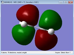
The fragments of both the reactants, in this case the 1,3-Cis Butadiene and the ethylene are both optimised using the semi-empirical AM1 theory. Once this is completed, the HOMO and LUMO of the reactants are visualised and the symmetry of the respectives HUMO and LUMO are determined.
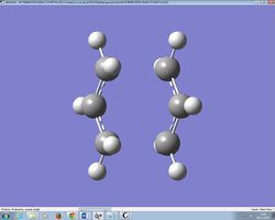
Figure 13: Optimised Structure Of 1-3 Cis Butadiene
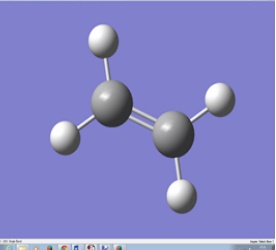
Figure 14: Optimised Structure of Ethylene
The table below shows the HOMO and the LUMO along with the symmetry of the respective molecular orbitals.
| Molecular Orbital | 1,3-Cis Butadiene | Ethylene |
|---|---|---|
| HOMO |  Anti Symmetrical Anti Symmetrical
|
 Symmetrical Symmetrical
|
| LUMO |  Symmetrical Symmetrical
|
 Anti Symmetrical Anti Symmetrical
|
Computation of Transition Structure Of 1,3-Cis Butadiene and Ethylene Cycloaddtion
The transition state of this particular reaction was built by approximately estimating how the reaction would proceed. As this was a symmetrical reaction, there wasn't any endo and exo product hence it is safe to assume that the transition state would be planar. Once this was done the transition state was optimised using a semi empirical AM1 method. Once the the ransition state was obtained, a frequency calculation was carried out in order to obtain the vibrational frequency which in this case was -956.35. The HUMO and the LUMO was also visualised in order to futher understand how the reaction proceeds on a molecular orbital level. The symmetry of the molecular orbitals were also determined.
Transition State of 1,3-CisButadiene and Ethene |
Figure 15 : Optimised Transition State of 1,3-Cis Butadiene and Ethylene Cycloaddtion
The length of the partly formed C-C σ bond was around 2.11Å in comparison to literature value [4]of 2.27Å. The length of a typical sp2 C-C bond is around 1.34Å and a typical sp3 C-C bond is around 1.54Å. The Van Der Wall radius of a typical carbon atom would be 1.70Å and the covalent bond length would be that of 3.4Å. The length of the partially formed bond of the transition state indicate that the bond formed isn't fully a covalent bond or a typical C-C bond as it lies in between the two values. This shows that the structure is somewhat of an intermediate.
The figure above shows the animation of how the reaction would proceed via the transition stage. A synchronous reaction is when bond breaking and bond forming happens at the same time. It is also known as a concerted reaction. A asynchronous reaction is also known as a step wise reaction in which the bond breaking and forming would not occur at the same time.
Figure 16 : HUMO of the transition state
As seen above the HOMO of the transition state is of an symmetrical geometry. A diels alder reaction is allowed only if the orbitals that overlap are that of the same symmetry. As shown earlier on, the HOMO of the 1,3-Cis Butadiene would interact with the LUMO of the Ethylene. The electron density is significantly greater at the position in which the σ bonds are supposed to be formed.
Cyclo hexa-1,3-diene and Maleic Anhydride
The cycloaddition between cyclohexa-1,3-diene and maleic anyhride is not symmetrical as the previous reaction. Hence the product formed would be either an endo or exo product. As this reaction is kinetically controlled, the more kinetically kinetically stable product is more likely to be formed. And this is the endo product. Thus when calculations are carried out, this particular transition state should have a lower energy than that of the exo transition state. Thus in order to verify this statement, the transition states for both the exo and endo product are optimised using a TS Berny method with the force constant being calculated once. The basis set theory that was used was semi empirical AM1.
Optimisation of Endo and Exo Transition State
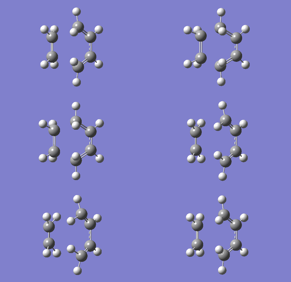
The structure of both the cyclohexa-1,3-diene and maleic anhydride was drawn and the structures were optimised using a TS berny optimisation method using the semi empirical AM1 set basis theory. Once this was completed, the approximate transition state for both the endo and exo was drawn as well and optimised using the same method. When the energy of these transition states were compared, the endo transition state (-612.70 a.u) had a lower energy value that the exo (-612.69 a.u). The diagrams below show the optimised structure of both of the transition state.
Transition Structure of Exo Product |
Transition Structure of Endo Product |
Figure 17: Transition states of both endo and exo product
In the exo product, the length of the partly formed C-C bond is that of 2.77Å and in the endo product the it is 2.83Å. In the endo and exo transition state, the C-C has a length of 1.55Å and the C=C is of a shorter length of 1.39-1.40Å. The length of the C-O is 1.4Å and the length of the C=O is 1.20Å. For an endo structure the distance between the carbon on the (C=O)-O-(C=O)- fragment of the maleic anhydride and the carbon of the other fragment is around 2.99Å. While on the exo structure, this distance is 3.02Å. This shows that the maleic anhydride fragment is being pushed away in the exo transition state and being pulled in during the formation of the endo transition structure. In an endo product, the electonegative oxygen atom is more likely to pull electron away from the diene hence stabilising the overall product. Thus, this is why it leads to a much more stable end-product. Where else in the exo product, as the maleic anhydride points away from the diene, the oxygen atom is not able to stabilised the higher electron energy of the product that is formed.
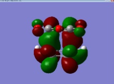
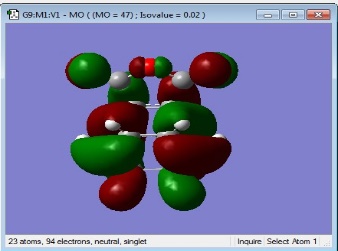
The HOMO of both the transition structures are visualised as below.
Figure 18: HOMO of EXO structure
Figure 19: HOMO of ENDO structure
In the endo product, there is no nodes observed between the oxygen atom and the opposing fragments. A node is a place in which the probability of finding an electron is zero. Hence, the absence of a node in the endo structure would indicate that there is a maximum overlap of the orbitals in this transition state. A greater overlap would indicate that the electron energy that was increased is more spread out hence forming a much more stabe product. This is the opposite for the exo transition state. By observation, there is a presence of a node in between the oxygen atom and the opposing fragmetns. Hence, there is less likely to be a greater overlap thus reducing the ability of the product formed to be much more stabilisd. Thus, it can be concluded that the endo product is more likely the more kinetically stable product and this reaction is most likely to pass through the endo transition state.[5]
CONCLUSION
The use of GaussView has allowed the calculation of the energy values of transition states and provided a clearer picture of how a reaction proceeds. The influence of orbital effects in the formation of certain products have also been rationalised using the computational method.
REFERENCES
- ↑ https://wiki.ch.ic.ac.uk/wiki/index.php?title=Mod:phys3#Optimizing_the_Reactants_and_Products
- ↑ http://pubs.acs.org/doi/pdf/10.1021/jo00384a016
- ↑ http://chemistry.tutorvista.com/organic-chemistry/addition-reaction.html
- ↑ http://pubs.acs.org/doi/pdf/10.1021/ja9601494
- ↑ http://pubs.acs.org/doi/pdf/10.1021/ja00747a052


