Rep:Mod3:em207
Edward Moore Module 3
Cope Rearrangement
The cope rearrangement is a very interesting reaction in which a [3,3] spectroscopic shif occours. In this section the reactants will first be investigated followed by the transition structures.
Optimising Reactants and Products
The calculation was set up with the input file coded as
%mem=500MB
%chk=C:\Documents and Settings\em207\My Documents\Computing labs\Module 3\Cope Rearrangement\Input\1_5_hexadiene_opt_1_anit.chk
# opt hf/3-21g geom=connectivity

1,5-hexadiene opt 1 anti

0 1
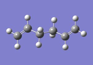
This gave the following output log file and structure. From which it was noted that the energy of the conformation was -231.69260236au and the point group was C2.
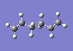
The same process was repeated for the Gauche conformer and this gave the following log output file and structure from which the energy was said to be -231.69166702au and the point group was C2. From the two calculation it can be seen that the Gauche form is more stable than the anti peri planar form, and from the literature[1] it can be seen that this is, indeed the most stable form, as this will minimise the steric interactions between the sp3 carbon and sp2 carbon centres. The Gauche form was further manipulated to minimise the structures energy further giving the following output log file and structure that the output-energy and point group of -231.68771614au and C2 respectively which was predicted to be the lowest energy conformation of the 1,5- hexadiene. This was confirmed to be the lowest energy conformer as when compared to Apendix1 the energy obtained was very similar.
Next the anti2 form was drawn and the resultant log file examined. The energy output from this section was -231.69253529 and the point group was as Ci. The resulting structure from this was then re-optimised using the higher basis set of B3LYP/6-31G(d) giving the following output file. The geometries of the structures were compared, see table below:
It can be said therefore that there is a significant change in the both the bond angles and bond lengths when the valuation is shifted from the HF/3-21G to the B3LYP/6-31G* level. However it can be said that the time taken for the calculation must be considered as with the increase in accuracy in the basis set (here there is an increase from 47 seconds to 6 minutes 8.0 seconds). It can be said therefore for larger molecules there will have to be a trade off between accuracy and computation time.
The following data was abstracted from the log file of the vibration analysis at the basis set, nb no imaginary frequencies were detected and therefore this is a correct optimisation:
| Energy contribution | Energy Value |
|---|---|
| Sum of electronic and zero-point Energies (E=Eelec + ZPE at 0K) | -234.469212 |
| Sum of electronic and thermal Energies (E=E+Evib+Erot+Etrans 298.15 K and 1 atm) | -234.461856 |
| Sum of electronic and thermal Enthalpies (H=E+RT) | -234.460912 |
| Sum of electronic and thermal Free Energies(G=H-TS) | -234.500821 |
The table above gives the values for the thermo chemistry for the anti-2 conformer of the 1,5 hexadiene at the B3LYP/6-31G(*) basis set. These values were calculated at 298.15K. It is predicted that at 0K the energy would be higher, ie less negative than at 298K, ie the conformer is less stable at the higher temperature as more energy is required to overcome the higher vibrational, rotational and translational energies for the anti-2 conformation at 0K.
Optimizing the "Chair" and "Boat" Transition Structures
In this section the chair and boat transition structures were modelled by several different methods
Chair
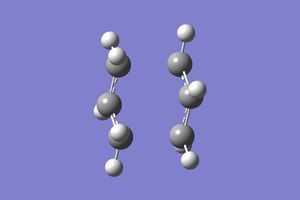
In this section the chair transition structure was modelled by 3 separate methods, the TS (Berny, the redundant coordinate method and then using the resultant geometry the reaction pathway was mapped using the IRC method. This gave the results bellow whilst using the Hartree Fock method and the 3-21G basis set. This gave the results bellow from the output files for the TS (Berny) and Frozen Coordinate method.
| Parameter | Optimisation to TS (Berny) | Frozen Coordinate method | ||||||
|---|---|---|---|---|---|---|---|---|
| Bond forming bond length/Å | 2.02052 | 2.02012 | ||||||
| Bond breaking bond length/Å | 2.02053 | 2.02092 | ||||||
| Diels Alder reaction frequency/cm-1 | -817.91 | -817.91 | ||||||
| Electronic Energies/au | -231.61932247 | -231.61932247 | ||||||
| Structures |
|
|
It can be seen from the above results that the TS Berny is more accurate than the frozen coordinate method as the bond lengths of the forming and breaking bonds are of a more similar value in the TS Berny than the frozen coordinate method. It can therefore be suggested that the TS Berny method be used for smaller molecules or for where a higher degree of accuracy is required, the opposite may therefore be said of the frozen coordinate method.
IRC
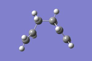
In this section the previously optimised geometry was taken and submitted to an IRC calculation in the forwards direction for the chair conformer to predict the reaction pathway. This gave the following log file for a 50 point IRC plot with the force constants calculated for every point. Which gave the coordinate bellow from which it can be seen that the initial geometry, in the forward sense, has reacted to go to a minimum and therefore the products. However it can be seen that the product is actually the Gauche 2 and not the formally lowest energy conformer Gauche 3, this could be due to the fact that the Gauche 2 is the first local minimum along the reaction coordinate.
| IRC reaction curve | Intermediate | Product |
|---|---|---|
 |
 |
 |
Boat
In this section the transition structure was modelled in two separate ways using TS(QST2).
TS(QST2)
In this section TS(QTS2) was used to obtain the intermediate. It should be noted that the calculation required the starting materials and products, in which the atoms had to be labelled initially in the reactants and then in their correct positions after the reaction had occurred, in order to do this the following method was employed number the atoms, the cyclic skeletal structure was numbered first followed by the substituent atoms i.e. the carbons were numbered first and then the hydrogen’s. It should be noted that if the atoms are not labelled correctly, i.e. that the atoms as numbered in their starting positions should be given the same number in the starting product. This gave the resulting structure and the information as extracted from the log file.
| Parameter | Value |
|---|---|
| Vibration frequency/cm-1 | -840.21 |
| Forming bond/Å | 2.12840 |
| Breaking Bond/Å | 2.14068 |
| Electronic energy/au | -231.60280319 |
| Image | 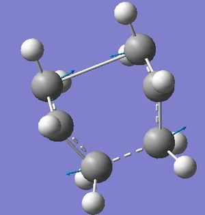 |
It can be seen from the above results that the chair structure is at a higher energy than the boat intermediate i.e. is more positive. It can also be seen that there is a significant difference between the forming and breaking bond, 0.03Å. It can also be seen that the imaginary frequency does represent the reaction and therefore represents the rearrangement occurring.
Activation Energy Calculations
In this section the activation energies of the chair and boat conformers for the cope rearrangement were calculated at the B3LYP/6-31G* level of theory. This gave the following output files for the chair and boat conformers. This was done by taking the sum of electronic and thermal free energies and multiplying this by 627.509 to get the energy of intermediate geometry in kcal mol-1, which was then subtracted from the starting materials energy to give the activation energy in kcal mol-1.
| Properties | Chair | Boat |
|---|---|---|
| Sum of electronic and thermal free energies/Hartrees | -234.443813 | -234.431768 |
| Activation Energy, ΔE/kcal mol-1 | 35.77 | 43.33 |
| Activation Energy, ΔE/kcal mol-1 literature values | 33.17 | 41.32 |
From the above table it can be seen that the activation energy for the boat is lower than the chair as would be expected, due to the difference in the steric repulsion forces in the transition states. However it may be said in comparison to the literature values from Appendix 2, that there is a small error for both the chair and the boat conformers in comparison to the experimental values. This may be due to the transition structures not being optimised to the absolute energy of the transition structure. However when the time available was considered against the accuracy it may be said that this result is an acceptable one.
Diels Alder Reactions
In this section the selectivity and reaction mechanism of the delis alder reaction was studied.
Cis Butadiene
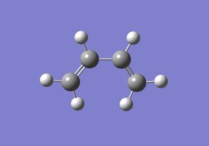
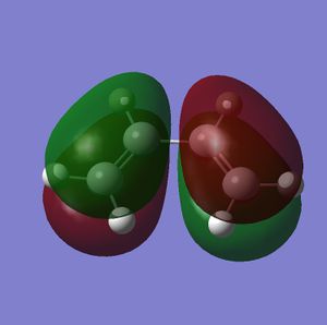
In this section a semi-imperial AM1 calculation was carried out and the HOMO and LUMO of Cis butadiene studied. This gave the following log file and resulted in the HOMO and LUMO as pictured bellow.
| Optimised Structure | HOMO | LUMO |
|---|---|---|
 |
 |
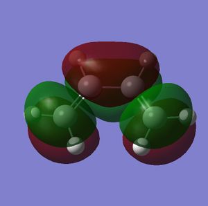 |
It can be seen from the above pictures that the HOMO is asymmetric and the LUMO is symmetric with regard to the plane as defined in the script (perpendicular to the C2-C3 bond.
Diels Alder reaction between Cis Butadiene and Ethane
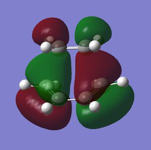
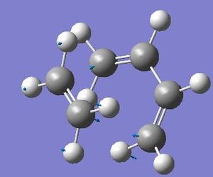
In this section the transition state geometry was isolated using TS (Berny) at the HF 3-21G level and then submitting this to IRC calculation in both the forwards and reverse direction along with a frequency analysis to prove that the transition state geometry obtained was indeed the transition state. This optimisation and frequency analysis resulted in the following log file and the transition state structure and HOMO and LUMO as shown bellow. It can be said in this case the vibration analysis resulted in one imaginary frequency output again as shown bellow which was characteristic of the concerted Deils alder reaction that was occurring here. The IRC calculation resulted in the following output file with the IRC plot shown bellow
| Property | TS Geometry | TS HOMO | TS LUMO | Imaginary Vibration | IRC Plot | |||
|---|---|---|---|---|---|---|---|---|
| Image |
|
 |
 |
 |
 |
From the above diagrams several conclusions can be made, firstly that the following geometries apply:
| Geometry variable | heading |
|---|---|
| Partly formed σ distances | 2.12 |
| All c=c bond lengths | 1.38 |
From the above table it can be seen that the partly formed σ bonds not of typical Csp3-Csp3 bond lengths (1.54Å[2]). It can also be said that the pseudo σ bond is not within the range of the Van der Waals radius of a C atom (1.7Å[2]). Therefore implying that this is not a fully fledged σ bonds or are there Vand der Vaal interactions occurring but instead overlap between the molecular orbital’s of ethene and the cis dibutadiene respectively.
Secondly it may be said that the imaginary frequency does imply that a synchronous process is occurring, however on studying the vibrations more carefully the first real vibration involves a rotation of the ethene in the molecular plane and thus implying a degree of asyncorarity about the process, it is subjected that were calculations run at a higher degree of accuracy that the result would be an imagery frequency at a lower level, i.e. more positive which would incorporate the existing imaginary frequency and the first real frequency.
Thirdly it can be said that the HOMO is anitsymetric and the LUMO is symmetric, this is as the same with the ethene and the cis butadiene, i.e. emphasising the fact that for the orbital’s to overlap they must have the same symmetry properties and therefore the reaction is controlled by the HOMO of the Cis butadiene overlapping with the LUMO of the ethene (which also have the better match in orbital energies).
Finally it can be seen from the IRC calculation that the reaction that has occurred is an exothermic one and the intermediate identified was indeed the intermediate for the given process.
Deils Alder reaction between Cyclohexa-1,3-diene and Malaic Anhydride
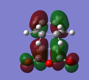
In this section the transition state geometry was identified using TS (Berny) and then submitting this to a vibration analysis and IRC calculation in both the forwards and reverse direction in order to prove that the transition state geometry obtained was indeed the transition state. This optimisation and frequency analysis resulted in the following log files for the endo and exo and the transition state structures and HOMO's and LUMO's as shown bellow. The IRC calculation resulted in the following output files for the endo and exo isomers and the IRC plots as shown bellow.
It can be seen from above table that the intermediate geometries are indeed the intermediates for the reaction. It can also be seen from the table above that the endo is more stable than the ego geometry (as it has a shorter c-c forming bond and also a lower geometry energy. It can also be said that the endo will be less stericly strained due to the fact that there are reduced sterics in the endo than in the exo.
It may be said that this stabilisation may be due to favourable secondary orbital interactions which are present in the endo and not the exo, thus stabilising the endo over the exo. It may be said in this case that the stabilisation arises from the electron density of the carbonyl carbons overlapping with the electron density on the carbons of the forming C=C bond, as this overlap can only occur in the endo and not the exo the exo will be at a higher energy (ie more positive) therefore favouring endo formation over the exo formation. It can also be seen that there is are 2 nodal planes in the endo and 1 nodal plane in the exo.
In conclusion it can therefore be said that endo is both the kinetic and thermodynamic product of this reaction and therefore it is predicted that there will be selectivity towards the endo product.

