Rep:Mod2:cc1007
Analysis of Optimised Molecules
Creation and Optimisation of BH3
Optimisation DOI: https://www.ch.ic.ac.uk/wiki/index.php/Image:CAROLINE_BH3_OPT2.LOG
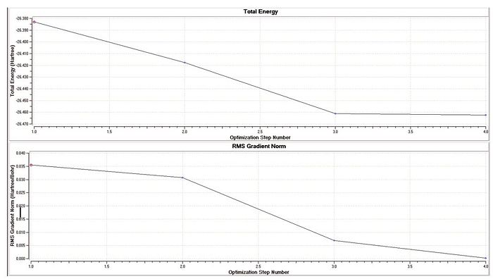
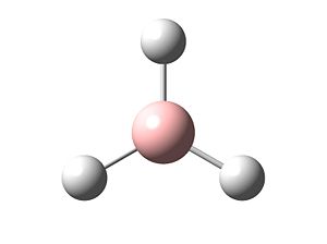
The molecule BH3 was drawn in Gaussview, and the calculation to find its optimum structure carried out over the Gaussview interface. A very minimal, basic basis set used: 3-21G. This was used to provide a rough estimate of the bond lengths and bond angles of the molecule, which are displayed in the table below. The optimisation was carried out by finding the lowest energy conformation of the molecule. The top graph (to the right) shows the decreasing energy of the system as the molecule is placed in more energetically favourable conformations. The graph underneath shows the gradient of the change of energy with eachoptimisation step. As observed, by the end of the calculation (by the final step) the gradient reaches zero, showing that the lowest energy conformation has been achieved.
 |
| File Type | .log File |
| Calculation Type | FOPT |
| Calculation Method | RB3LYD |
| Basis Set | 3-21G |
| Spin | Singlet |
| Final Energy/kJ mol-1 | -26.46 a.u. |
| Final Gradient | 2.067 x 10⁻⁴ |
| Dipole Moment | 0.00 |
| Point Group | D3h |
| Time taken | 21 seconds |
| B-H Bond length | 1.19 Angstroms |
| H-B-H Bond angle | 120o |
Analysis of Molecular Orbitals of BH3 and NBO Calculation
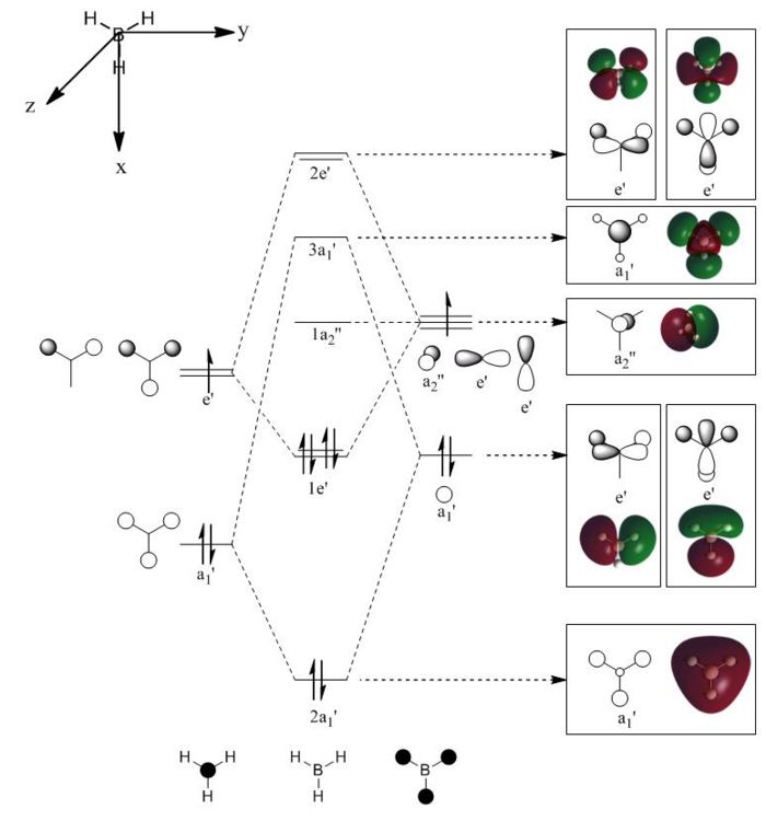
To observe the orbital size and electron density in the various energy levels of BH3, calculations were run to predict the molecular orbital surfaces within the molecule. Again, DFT (Density Functional Theory) was used, but for this calculation a more complex basis set was used: LANL2DZ. This produces more accurate results that the 3-21G basis set used in the previous section. DOI:10042/to-4416
The image to the right shows Molecular Orbital Diagram dervived from LCAO theory. Orbital surfaces generated with Gaussview have been added for direct comparison. Shows that MO surfaces generated by LCAO theory are actually very accurate! However, a limitation to LCAO theory is that it cannot compute the relative energies of the orbitals, although assumptions can be mage. When compared to the table below, it is evident that the degenerate Orbitals 6 and 7 should be lower in energy than Orbital 8, but this is not taken into account in the MO diagram.
| MO no. | Diagram | Relative Energy | Symmetry |
|---|---|---|---|
| 1 | 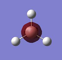 |
-6.73 | a1' |
| 2 | 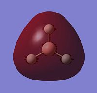 |
-0.52 | a1' |
| 3 | 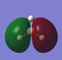 |
-0.36 | e' |
| 4 |  |
-0.36 | e' |
| 5 | 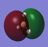 |
-0.07 | a2 |
| 6 | 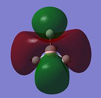 |
0.18 | e' |
| 7 |  |
0.18 | e' |
| 8 | 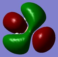 |
0.19 | a1' |
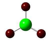
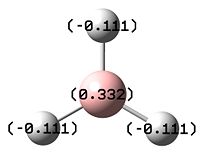
The other piece of data that can be obtained from this Molecular Orbital calculation is the NBO analysis, which can give both a pictoral and a quantitative view of the charge density localised on atoms around the molecule. Thus, for BH3, Gaussview can give us a quick representation of the charge on B and H by colouring the atoms more red to denote a comparatively positive charge (low electron density) or green to denote a relatively negative charge (high electron density). It can also give more numerical results, stating the relative charge density on each atom.
The images to the right show that with both a red hue and a positive charge density value of 0.332, boron is the more electropositive atom in the molecule. On the other hand, the three hydrogens are tinted green and each have a negative NBO value of -0.1.11, showing that most of the electron density in the molecule is centred on them. As BH3 is a neutral molecule, the overall charge of the molecule when all the charges on the respective atoms are added up gives zero.
The log file of the NBO calculation gives additional quantitative data not shown in the pictoral representations such as the occupancy (bond order) of each bond, its energy, and the relative magnitude of its s and p character. This can be related back to the MO theory shown above.
| Molecular Orbital | Occupancy | Energy | % Electron density on B | % Electron density on H | %s character | %p character |
|---|---|---|---|---|---|---|
| 3x B-H Bonding | 1.998 | -0.437 | 44.5 | 55.5 | 33.3 | 66.7 |
| B 1s | 1.999 | -6.644 | 100.0 | 0.0 | 100.0 | 0.0 |
| B (LP) | 0.000 | 0.676 | 100.0 | 0.0 | 100.0 | 0.0 |
| B Empty 2p | 0.000 | 0.371 | 100.0 | 0.0 | 0.0 | 100.0 |
| 3x H | 0.0003 | 0.900 | 0.0 | 100.0 | 100.0 | 0.0 |
| 3x B-H Antibonding | 0.0001 | 0.412 | 55.5 | 45.5 | 33.3 | 66.7 |
The data above confirms that the three B-H bonding orbitals are produced as a hybrid of one s and two p orbitals. In line with the NBO analysis and MO diagram above, most electron density is present in the bonding orbitals of the hydrogen atoms. However, it appears that the unoccupied boron orbital, B(LP) is purely of s-character, when it should actually be an empty p-orbital, the 2pz which is unengaged in bonding. This is likely to be as a result of an insufficient basis set.
Vibrational Analysis of BH3
BH3 Frequency Calculation: https://www.ch.ic.ac.uk/wiki/index.php/Image:CAROLINE_BH3_FREQ.LOG
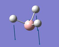
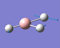
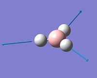
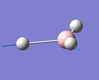
The stretching frequencies of BH3 were calculated with the DFT RB3LYP as before, with a basis set of 3-21G used for consistency. The total energy calculated for the stretching frequencies was almost identical to that produced for the optimisation calculation, confirming that a low-energy minimum in the conformation of the molecule had been reached. As BH3 has D3h symmetry, each stretching frequenc will correspond to a point group from that symmetery label.
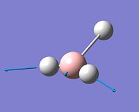
As a non-linear molecule, BH3 contains 3n-6 (or 4x3 - 6) stretches, which corellate to the six shown in the table below. It is of note that not all of these will appear on the I.R. spectrum, as some stretches (such as stretch 4, with a' symmetry) are completely symmetrical have no overall dipole moment. The larger the dipole moment of the stretch, the higher the intesity in the I.R. spectrum.
Creation and Optimisation of BCl3
BCl3 Optimisation DOI: https://www.ch.ic.ac.uk/wiki/index.php/Image:CAROLINE_BCL3_OPT.LOG
For this calculation, the DFT-B3LYP method is used again, but a larger basis set than 3-21G is used: LanL2MB. This provides calculations which take longer to run, but are more accurate. The LanL2MB basis set contains pseudo-potentials, or approximations for Schrodinger's equation [1] which apply to heavier atoms such as chlorine as well as boron and hydrogen.
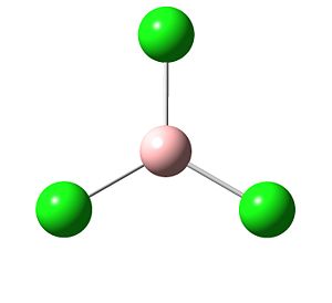 |
The calculations run showed that the at 120o, the bond angles were similar to that of BH3, suggesting sp2 hybridisation. However, the bond lengths were longer. This is expected as B-Cl bonds are typically longer than B-H bonds, Cl being larger than H. However, they are slightly longer than the literature value of 1.72A[2], suggesting that the basis set can still be further improved. Upon optimisation, Gaussian sometimes removes the formal bonds between atoms as they are longer than the 'expected' typical bond length between two atoms. When this length goes beyond a certain value, Gaussview automatically removes the formal bond which denotes that the atoms are close enough together to be considered bonding. However, bonding is simply the presence of electron density between two atoms, i.e. the probability of an electron being between the two atoms. Thus, although Gaussview sometimes does not denote a formal bond, it can still be there.
The point group remains, as in BH3, D3h, so it is expected that there will be some similarity in the vibrational stretching modes.
| File Type | .log File |
| Calculation Type | FOPT |
| Calculation Method | RB3LYD |
| Basis Set | LANL2MB |
| Spin | Singlet |
| Final Energy/a.u. | -69.44 |
| Final Gradient | 0 |
| Dipole Moment | 0.00 |
| Point Group | D3h |
| Time taken | 3 seconds |
| B-H Bond length | 1.87 Angstroms |
| H-B-H Bond angle | 120o |
Vibrational Analysis of BCl3
BCl3 Frequency Calculation DOI: https://www.ch.ic.ac.uk/wiki/index.php/Image:CAROLINE_BCL3_FREQ.LOG
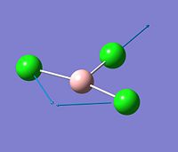
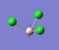
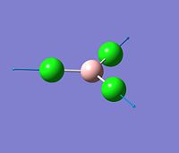
The stretching frequencies of BCl3 were calculated with the DFT RB3LYP as before, with a basis set of LANL2MB used for consistency with the optimisation basis set. The total energy calculated for the stretching frequencies was almost identical to that produced for the optimisation calculation, confirming that a low-energy minimum in the conformation of the molecule had been reached. As BCl3 has D3h symmetry, each stretching frequency will correspond to a point group from that symmetery label.
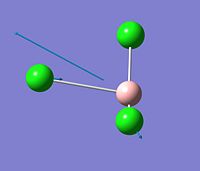
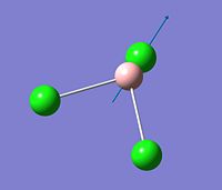
As a non-linear molecule, BCl3 contains 3n-6 (or 4x3 - 6) stretches, which corellate to the six shown in the table below. It is of note that not all of these will appear on the I.R. spectrum, as some stretches (such as stretch 4, with a' symmetry) are completely symmetrical have no overall dipole moment. The larger the dipole moment of the stretch, the higher the intesity in the I.R. spectrum.
Cis and Trans Isomerism of Mo(CO)4(L)2
This is an area of project carried out the explore how geometrical isomerism can affect the energetic and spectral (Infrared) properties of a molecule. The two isomers of Mo(CO)4(L)2 will be explored, where the two L groups can be either cis or trans to each other. In the literature, L is usually triphenylphosphine, but due to the time limitations of modelling such a large molecule, it will be replaced instead with PCl3[3]. This has similar properties in terms of electron-withdrawing ability and will be much quicker to model.
Creation and Optimisation of cis-Mo(CO)4(Cl)2
Optimisation: DOI:10042/to-4411
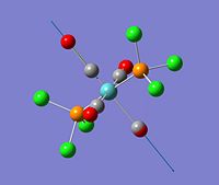
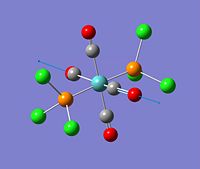
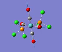
The cis-isomer was optimised first with a low-level basis set, 3-21G, to get a rough estimation of bond lengths and angles. This was followed by a larger basis set, LANL2MB. The rotational conformation of the six chlorine atoms was altered to ensure they were in an orientation which would result in the lowest energy minimum upon further optimisation. The molecyle was then optimised for the third and final time with an even larger basis set, LANL2DZ, to allow the molecule to reach its optimum geometry. The bond lengths compared reasonably well with the literature [4], suggesting that the molecule has been correctly optimised.
 |
Vibrational Analysis of cis-Mo(CO)4Cl2
Frequency: DOI:10042/to-4413
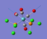
Due to their symmetrical stretches, both stretches 3 and 4 will not appear in the I.R. spectrum. However, as two of the carbonyls are in different environments to the other two (one pair are trans to a Cl atom and the other are trans to another carbonyl) they will obtain stretching frequencies at different energies. Thus, the stretching frequencies of stretches 1 and 2 are inequivalent, resulting in two peaks in the I.R. spectrum.
Creation and Optimisation of trans-Mo(CO)4(Cl)2
Optimisation: DOI:10042/to-4412
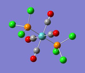
Upon the 3rd optimisation with the LANL2DZ basis set, the trans-isomer is found to be marginally lower in energy than the Cis-isomer. This is likely ti be due to the fact that although chlorine is a good electron-withdrawing group, carbonyls are much better π-acceptors and can induce backbonding back onto the d-orbitals of the Mo metal centre, stabilising it. In the trans isomer, the four carbonyls are trans to each other and thus compete for electron density, inductively withdrawing the backbonded electrons to backbond them through the π system. On the other hand, in the cis conformation, chlorine atoms lie across from the carbonyls, and due to the trans effect, the carbonyls are able to remove electron density from the chlorine atoms and backbond them onto the metal centre. Another reason for the comparative stability of the trans isomer is its dipole moment. The trans isomer has a much smaller dipole moment (0.305D) than its cis counterpart (1.309D), making it more symmetrical and less prone to destabilisation. Also, the fact that chlorine is much smaller than PPh3 must be taken into account. The trans isomer will be stabilised compared to its cis counterpart as it is less sterically strained, and this would be much more of an issue with a large triphenylphosphine ligand than a relatively small PCl3 one.
 |
Vibrational Analysis of trans-Mo(CO)4Cl2
Frequency: DOI:10042/to-4414
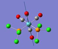
Some stretches not seen in I.R. spectrum due to symmetry of molecule producing no overall dipole. Thus,only the first two asymmetric stretches are observed. As they are degenerate, only one main peak is observed in the I.R. spectrum.
Mini-Project: Analysis of Fluoride Interhalogen Compounds
The aim of this project is to use computational analysis to explore the relative energies, ideal bond lengths and Molecular Orbital surfaces of the Fluoride interhalogens. These results will be used to rationalise the reactivity of the interhalogens and their Lewis-acidic behaviour.
Bonding and Structure of XF3
ClF3 Optimisation: DOI:10042/to-4686 BrF3 Optimisation: DOI:10042/to-4546 IF3 Optimisation: DOI:10042/to-4547
ClF3 MO Calculation: DOI:10042/to-4688 BrF3M O Calculation: DOI:10042/to-4589 IF3 MO Calculation: DOI:10042/to-4690
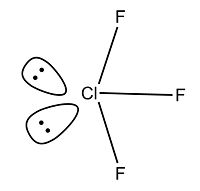
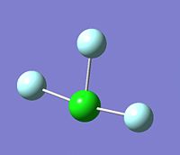
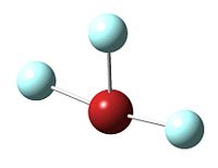
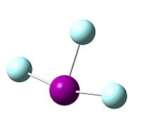
The structure of the XF3 fluoride interhalogens comprises a T-shaped structure which takes into account the presence of the two lone pairs on the chlorine central atom and makes steric accomodations accordingly[5]. The shape of the molecule as a whole is trigonal bipyramidal[6]. In this section of the report, the bonding and structure of the three main XF3 interhalogens will be explored.
To find the optimum conformation of each molecule, the DFT-BYLRP method was used. A low accuracy basis set, the 3-21G was first used to obtain a rough estimation of the angles and bond lengths in each molecule. This was followed by use of a larger basis set, the LANL2DZ, to further optimise the geometries of the molecule. This provided a good base upon which to later calculate the NBO charges and explore the molecular energy surfaces of the molecule, as the same basis set would have to be used.
The three molecules were found to have very similar structures and energies (displayed and discussed in the results section below). The calculated lowest energy conformation was found to agree with that mentioned above in the literature; a bent T-shape which allowed for the steric repulsion of the two lone pairs on each central molecule.
The results below show that the 'apical' fluoride opposite to the two lone pairs consistently has a lower negative charge density than the two fluorides which are trans to each other across the central atom. The bond length between the apical fluoride and the central atom is consistently also shorter in all three compounds. This trend is mentioned in the literature[7], although the calculated bond lengths are slightly higher than those experimentally determined, suggesting that again, a larger basis set might have to be used to obtain very accurate results. However, due to time constraints and the fact that this project aims more to explore the structure and charge density of the molecules than to obtain strictly quantitative values for the bond lengths, the LANL2DZ basis set will be used as it has been shown to achieve a decent approximation.
| Image of ClF3 | Image of BrF3 | Image of IF3 |
|---|---|---|
 |
 |
 |
As mentioned in the section above, the two fluoride ions trans to each other have longer X-F bond lengths than the single apical fluoride. One reason for this is displayed below; the NBO charge density analysis shows that a larger degree of negative charge is present on the trans-equatorial atoms, increasing their repulsive interactions and lengthening the bond. VSEPR theory[8] predicts that these two fluorides will bond to the central atom in a 3c-4e bond (Three-centre four electron), producing a bond order of 0.5.
In contrast, the single apical fluoride is lower in charge density and more electropositive. It has been suggested that this fluoride interacts with the central halogen atom in a 2-centre-2-electron (2c-2e) bond[9] as it is opposite the two lone pairs, which must, by definition, be in sp2 hybridised orbitals to be stereochemically active. This gives the apical hydrogen a bond order of 1, justifying its shorter bond and lower electron density compared to the two trans- fluorides.
| NBO of ClF3 | NBO of BrF3 | NBO of IF3 |
|---|---|---|
 |
 |
 |
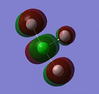
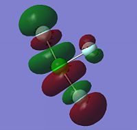
The Molecular Surfaces shown below were calculated using the same basis set as the optimisation: LANL2DZ. The molecular orbitals for the HOMO-1, HOMO, LUMO and LUMO+1 are displayed only for ClF3, as the molecular orbital surfaces for all three interhalogens were found to be very similar. It is evident that the vast majority of electron density is in the fluoride ions. In the HOMO-1, the electron density is all in the non-bonding interactions between the two trans fluorides and the central chlorine atom. Likewise in the HOMO, with the addition of electron density on the apical fluoride; there is none on the underside of the central atom where the lone pairs are, showing that if electron density is going to be transferred from the molecule, it will be done via the fluoride ions.
On the other hand, the LUMO shows a large empty molecular orbital where the lone pairs are sterically. This explains the behaviour of XF3 compounds as Lewis Acids; the empty hybridised orbital in the LUMO can readily be attacked by a Lewis base, making it an excellent oxidising and fluorinating agent[10].
| HOMO-1 of ClF3 | HOMO of ClF3 | LUMO of ClF3 | LUMO+1 of ClF3 |
|---|---|---|---|
 |
 |
 |
 |
Bonding and Structure of XF5
ClF5 Optimisation: DOI:10042/to-4692 BrF5 Optimisation: DOI:10042/to-4537 IF5 Optimisation: DOI:10042/to-4434
ClF5 MO Calculation: DOI:10042/to-4691 BrF5 MO Calculation: DOI:10042/to-4541 IF5 MO Calculation: DOI:10042/to-4540
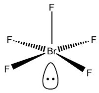
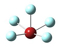
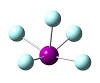
The structure of the XF5 interhalogens can also be predicted with VSEPR theory[11]. All three of the halogens explored in this project, Cl, Br and I, form pentavalent molecules with fluoride, producing a species with 12 electrons in their valance shell. This leaves two free electrons, or one lone pair, which is trans to the apical fluoride.
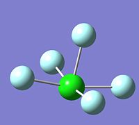
Optimisation of the three compounds was carried out in the same way as for the XF3 species; a low-accuracy basis set was used first, followed by the larger LAN2DZ basis set, all with the DFT-BYLRP method. As before, bond lengths were slightly longer than those found in the literature[12], although bond angle values were accurate to +50. The structure was certainly correct, with a square bupyramidal shape. The four basal fluorides were slightly raised towards the apical one (bond angles were approximately 80-89o to reduce the repulsion between the bonding and lone pairs, resulting in a slight distortion of the original octahedral unit.
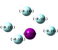
The structure of XF5 is typically square pyramidal, dervived from a slightly distorted octahedron with the removal of one bond. As before, the apical fluoride is expected to interact with the central halogen in the form of a 2c-2e bond, resulting in a bond order of 1. This makes it shorter and stronger than the bonds between the basal (equatorial) fluorides and the central atom, as they form 4c-6e bonds with the central halogen, again resulting in a bond order of 0.5.
| Image of Optimised ClF5 Molecule | Image of BrF3 | Image of IF3 |
|---|---|---|
 |
 |
 |
| NBO of ClF5 | NBO of BrF5 | NBO of IF5 |
|---|---|---|
 |
 |
 |
Again, the Molecular Surfaces were calculated using the same basis set as for the optimisation, LANL2DZ. The molecular orbitals for the HOMO-1, HOMO, LUMO and LUMO+1 are displayed only for BrF3, as the molecular orbital surfaces for all three interhalogens were found to be very similar. In contrast to the molecular orbitals calculated for XF3, those for XF5 give the impression of a much more balanced charge density districution betweent the central halogen atom and the fluoride ions surrounding it. In the HOMO-1, electron density is entirely focussed on the equatorial fluorides, but the HOMO shows some electron density on the lone pair of BF5. This explains why it is not as good a Lewis acid or as aggressive an oxidising agent as ClF3. In spite of the large empty orbital in its place in the LUMO, the fact that a lone pair is there in the valance shell will make it less attractive to nucleophiles.
| HOMO-1 of BrF5 | HOMO of BrF5 | LUMO of BrF5 | LUMO+1 of BrF5 |
|---|---|---|---|
 |
 |
 |
 |
Bonding and Structure of XlF7
ClF7 Optimisation: DOI:10042/to-4693 BrF7 Optimisation: DOI:10042/to-4695 IF7 Optimisation: DOI:10042/to-4542
ClF7 MO Calculation: DOI:10042/to-4694 BrF7 MO Calculation: DOI:10042/to-4696 IF7 MO Calculation: DOI:10042/to-4543
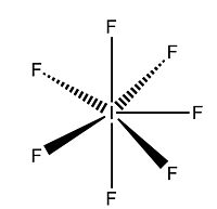
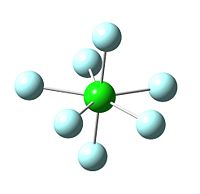
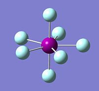
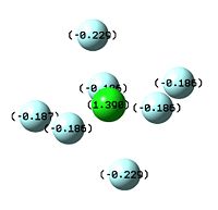
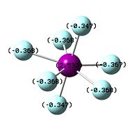
The image to the left shows iodine achieving a full heptavalent shell in a fluoride interhalogen. It is a pentagonal bipyramid in structure, with D5h symmetry; it is bonded to two axial fluorides and five equatorial fluorides, each 72o apart on a single plane. iodine is in fact the only halogen out of the three expored in this project which readily forms a heptavalent fluoride interhalogen. In the case of chlorine, the central chloride atom is simply too small to accomodate seven fluoride atoms around it due to their relative similarity in size. In addition, the fluoride ion is highly negative in charge, and being centred closely around a small atom would result in destabilising repulsions between the non-bonding atoms[13]. However, the cation ClF6+ can be formed as the positive charge on the Cl ion could then stabilise the field of negative charge surrounding it. This suggests that the main issue resulting in the destabilisation of ClF7 is electronics, not sterics.
Bromine, while larger and less electronegative than chlorine, also does not form its heptafluoride analogue. Surprisingly, this is less due to the repulsive non-bonding interactions of the fluoride ions, and more due to the reluctance of Br to achieve its maximum oxidation state[14]. This is observed in the results section below; the bond lengths of Br7 compared to Br5 are actually shorter, while for ClF7 they are much longer; however, then the NBO is observed, Br is actually reluctant to take on a large degree of positive charge. This is a product of the alternation effect, where supposedly less electronegative atoms are actually less inclined to take on a more positive formal charge than more electronegative ones.
| Image of Optimised ClF7 Molecule | Image of BrF7 | Image of IF7 |
|---|---|---|
 |
 |
 |
| NBO of ClF7 | NBO of BrF7 | NBO of IF7 |
|---|---|---|
 |
 |
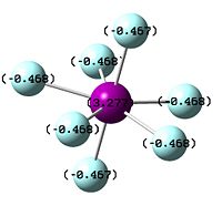 |
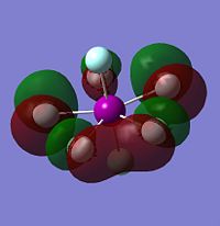
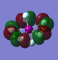
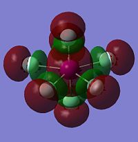
As with the other two sets of calculations, the Molecular Surfaces were calculated using the same basis set as for the optimisation, LANL2DZ. The molecular orbitals for the HOMO-1, HOMO, LUMO and LUMO+1 are displayed only for IF7, as the molecular orbital surfaces for all three interhalogens were found to be very similar, but also because it is the only XF7 interhalogen known to be isolatable. The molecular orbital surfaces found for XF7 are very different to those for either XF3 or XF5 due to the closed-shell nature of the compound. IF7 has no lone pairs or unpaired electrons, and is thus much more electronically stable than its lower valency counterparts.
Both the HOMO-1 and the HOMO energy levels are found to have electron density almost completely cocussed on the equatorial fluorides, explaining why their charge density is more negative than the axial fluorides. The LUMO and LUMO+1 show the presence of empty orbitals on all fluoride ions, including the axial ones. However, as they are all negatively charged, it is unlikely that they will be attacked by a nucleophile! As stated above, the full valance shell and lack of an empty central halogen orbital in the LUMO energy level explains the inert nature of IF7.
| HOMO-1 of IF7 | HOMO of IF7 | LUMO of IF7 | LUMO+1 of IF7 |
|---|---|---|---|
 |
 |
 |
 |
Discussion and Analysis
Relative Total Energies of the Interhalogens

General trend = increasing energy (i.e. total energy of molecule gets higher) down the group. When the central molecule is chlorine, the energy is -314.2 a.u., but it increases to -312.5 a.u. with BrF3 and -310.8 a.u. with IF3. The relationship is roughly linear, and applies also for the pentavalent and heptavalent versions of the three central atoms.
| Compound | Total energy/a.u. |
|---|---|
| ClF3 | -314.2 |
| BrF3 | -312.5 |
| IF3 | -310.8 |

As mentioned previously, increasing the valancy of the central halogen affects the total energies of Chlorine, Bromine and Iodine in roughly the same way, in spite of their differences in size, electronegativity and polarisability. Thus the calculated energies do not appear to have a great deal of corellation between the thermal or electronic stability of the interhalogen compounds; for example, although ClF7 and BrF7 both appear to have lower (more negative) total energies then IF7, as displayed in the table below, in actual fact, neither can be isolated. Physical properties such as the boiling point of the molecule are much more likely to be related to dipole moment or charge distribution than the calculated total energy.
| Compound | XF3 | XF5 | XF7 |
|---|---|---|---|
| ClFn | -314.2 | -513.7 | -713.1 |
| BrFn | -312.5 | -510.4 | -711.5 |
| IFn | -310.8 | -502.6 | -709.9 |
Relationship between Dipole Moment and Boiling Point of the Interhalogens
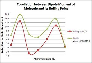
The graph to the right shows the corellation between the dipole moment of each compound in the table below and its experimental boiling point. The corellation is actually very good, confirming that the thermal properties of the molecule are more related to dipole than total energy. Compounds such as BrF3 or IF5 which have large dipole moments generally have higher boiling points, as there are larger intermolecular interactions. Due to bond length?
| Compound | Dipole Moment/D | Boiling point/oC |
|---|---|---|
| ClF3 | 1.49 | 12 |
| BrF3 | 3.98 | 126 |
| IF3 | 1.62 | -28 |
| ClF5 | 1.28 | -13 |
| BrF5 | 2.27 | 41 |
| IF5 | 3.42 | 105 |
| IF7 | 0.029 | 5 |
Relationship between bond lengths and increased valency of the Interhalogens
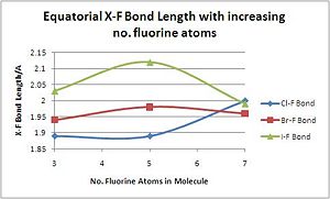
There is a general trend of increasing halogen-fluoride bond length with increasing valencyb with bonds in the equatorial (non-apical) plane. This is presumably due to electronic interactions as well as sterics, as bond lengths increase to reduce the repusive interaction between electrons. The exception to the rule is IF7, which significantly reduces its bond length from IF5. This is likely to be due to its large size, which reduces the problem of steric constraints, and its high polarisability and low electronegativity, which allow it to achieve its maximim oxidation state: a formal charge of +3 [15].
| Compound | XF3 | XF5 | XF7 |
|---|---|---|---|
| Cl-F Bond Length/A | 1.89 | 1.89 | 2.00 |
| Br-F Bond Length/A | 1.94 | 1.98 | 1.96 |
| I-F Bond Length/A | 2.03 | 2.12 | 1.99 |
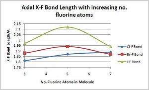
The axial (or apical) bond length is generally shorter than the equatorial one, most likely for electronic reasons; the bond angle between an axial and equatorial fluoride is usually between 80 and 90 degrees while that between two equatorial fluorides can reach 72 degrees. However, the trends down the group and with increased valancy are very similar to that of the equatorial hydrogens, again suggesting that Br and Cl are both more stable as lower-valancy fluoride interhalogens while Iodine is very happy to achieve its maximum oxidation state.
| Compound | XF3 | XF5 | XF7 |
|---|---|---|---|
| Cl-F Bond Length/A | 1.81 | 1.87 | 1.89 |
| Br-F Bond Length/A | 1.98 | 1.94 | 1.87 |
| I-F Bond Length/A | 1.97 | 2.12 | 1.94 |
Relationship between bond angles and increased valency of the Interhalogens
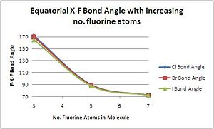
The bond angle between equatorial fluorides, as expected, decreases with increasing valency.
| Compound | XF3 | XF5 | XF7 |
|---|---|---|---|
| F(eq.)-Cl-F(eq.) Bond Angle/o | 86.1 | 84.8 | 89.9 |
| F(eq.)-Br-F(eq.) Bond Angle/o | 85.3 | 82.1 | 89.9 |
| F(eq.)-I-F(eq.) Bond Angle/o | 82.7 | 77.89 | 89.9 |
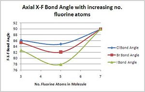
The bond angle between axial and equatorial fluorides is relatively constant compared to the equatorial-equatorial bond angle as the apical fluoride usually stays in the same place while the equatorial rotates around to allow another fluoride into the molecule.
| Compound | XF3 | XF5 | XF7 |
|---|---|---|---|
| F(ax.)-Cl-F(eq.) Bond Angle/o | 86.1 | 84.8 | 89.9 |
| F(ax.)-Br-F(eq.) Bond Angle/o | 85.3 | 82.1 | 89.9 |
| F(ax.)-I-F(eq.) Bond Angle/o | 82.7 | 77.89 | 89.9 |
NBO Analysis

General trend of increasing positive charge on the central atom with the addition of fluorine atoms. This is unsuprising as fluorine is more electronegative than chlorine, bromine or iodine and will remove electron density from the central atom. Down the group, the central atom also becomes increasingly positively charged as the central atom is more polarisable and electron density becomes easier to remove. The reason behind this is the decrease in ionisation energy as down the group chlorine is replaced by bromine which is replaced by the least electronegative of the halogens in this project, iodine.
| Compound | XF3 | XF5 | XF7 |
|---|---|---|---|
| Cl Charge Density | 0.86 | 1.38 | 1.39 |
| Br Charge Density | 1.29 | 2.05 | 2.31 |
| I Charge Density | 1.41 | 2.34 | 3.77 |
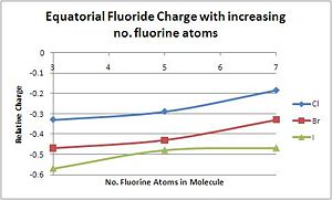
As expected, conversely to the central atom, the charge on the fluoride becomes increasingly negative down the group. The fluoride atoms on I are the most negative as it is the most readily polarizable halogen, allowing electron density to be easily removed. Chlorine, as the most electronegative atom, retains its hold on electron density, making the fluoride ions less negatively charged. For the equatorial fluorides, there is a clear trend of decreasing electron density (increasinly positive charge) on the fluoride atoms as more and more ions are added. This is due to the fact that bind orders are becoming weaker, with the same number of electrons shared between an increasing number of centres. For XF3, the equatorial hydrogens form a 3c-4e bond to the central atom; for XF5, it is a 4c-6e bond, and for XF7, it has become a 6c-10e bond.[16].
| Compound | XF3 | XF5 | XF7 |
|---|---|---|---|
| F(eq.)-Cl Charge Density | -0.33 | -0.29 | -0.18 |
| F(eq.)-Br Charge Density | -0.47 | -0.43 | -0.33 |
| F(eq.)-I Charge Density | -0.57 | -0.48 | -0.47 |

The trends are much more complex for the apical or axial fluorides. As with the equatorial fluorides, electron density on the fluoride ions increases down the group. The trends upon increasing valency are similar until XF5, but the electron density suddenly increases upon the generation of XF7. The slight difference between the electron densities of the fluorides on XF3 and XF5 can be rationalised by the supposition that in both, the apical fluorides are bonded to the central halogen by 2c-2e bonds, and thus, the electron density will stay fairly constant between the two. On the other hand, the case of the XF7 compound can be simplified by assuming that, as mentioned in the section above, iodine is the only halogen that can extend to a heptavalent complex[17].
IF7 is the only interhalogen where the valance shell of the central iodine atom is completely filled and there is no lone pair. Thus, the axial fluoride atom is no longer competing with a lone pair trans to itself for electron density, but another fluoride atom. As all the electrons on iodine are now engaged in bonding, there is a larger amount of electron density in the bonding orbitals which results in the charge on the two axial fluoride atoms becomming more negative.
| Compound | XF3 | XF5 | XF7 |
|---|---|---|---|
| F(ax.)-Cl Charge Density | -0.19 | -0.19 | -0.23 |
| F(ax.)-Br Charge Density | -0.35 | -0.34 | -0.33 |
| F(ax.)-I Charge Density | -0.47 | -0.41 | -0.47 |
Conclusion
Upon the optimisation of the nine interhalogens studied, bond angles were found to be very similar to those found in the literature, but bond lengths less so. This is put down to an insufficient basis set which was still, however, adequate for measuring the relative charge densities on each respective atom in the molecules and thus used because of time constraints.
NBO and molecular orbital calculations showed that the fluoride ions were sufficiently electronegative to remove electron density from the central halogen atom and give it a formal positive charge. This positive charge increased for halogens down the group (i.e. Cl<Br<I) as the atoms became larger, less electronegative and more polarisable. They also rationalised the differing reactivities of the three group interhalogens studied (XF3, XF5 and XF7). XF3 was found to be the most Lewis-acidic in spite of the smaller positive charge on the central atom. This is due both to the lack of steric hindrance to the central atom, and also its very low electron density; it has little electron density in the HOMO and a large empty orbital in the LUMO which can easily be attacked by a Lewis base. XF5 was found to be less prone to attack by a Lewis base because of its filled lone pair orbital in the HOMO which might repel an incoming electron pair, and IF7, with its closed shell and lack of any accessible orbital at all, was judged to be the most inert to reactivity.
Bond lengths, as expected, were found to increase down the group as the central atom became larger and there was a more pronounced discrepancy in size between it and the fluoride ion. Axial bond lengths were found to be consistently shorter than equatorial ones due to the nature of its 2c-2e bond. Axial fluorides thus had less electron density than equatorial ones to avoid repulsive interactions.
References
- ↑ Squires, Introduction to the Theory of Thermal Neutron Scattering, 1996, Dover Publications
- ↑ Henri A. Lévy, L. O. Brockway, J. Am. Chem. Soc., 1937, 59 (11), pp 2085–2092,
- ↑ 3rd Year Computational Lab Script
- ↑ Steric Influences on the chelation of ditertiary phosphine complexes of group VI metal carbonyls, J.A. Connor, and P.I. Riley, J. of Org. Chem, 1975, 94, 55-60
- ↑ O. J. Cunrow, J Chem. Edu, 1998, 75, 910-915
- ↑ Shriver and Atkins, Inorganic Chemistry, 4th edition, 2006, Oxford University Press, 408-409
- ↑ O. J. Cunrow, J Chem. Edu, 1998, 75, 910-915
- ↑ B.M. Gimarc, Molecular Structure and Bonding, 1979, 1st Edition, Academic: New York
- ↑ O. J. Cunrow, J Chem. Edu, 1998, 75, 910-915
- ↑ Shriver and Atkins, Inorganic Chemistry, 4th edition, 2006, Oxford University Press, 408-409
- ↑ T.A. Albright, J.K. Burdett, M.H. Whangbo, Orbital Interactions in Chemistry, 1985, Wiley: New York
- ↑ O. J. Cunrow, J Chem. Edu, 1998, 75, 910-915
- ↑ Shriver and Atkins, Inorganic Chemistry, 4th edition, 2006, Oxford University Press, 408-409
- ↑ Shriver and Atkins, Inorganic Chemistry, 4th edition, 2006, Oxford University Press, 408-409
- ↑ O. J. Curnow, 1998, J. Chem. Edu, 75, 910-915
- ↑ Shriver and Atkins, Inorganic Chemistry, 4th edition, 2006, Oxford University Press, 408-409
- ↑ Shriver and Atkins, Inorganic Chemistry, 4th edition, 2006, Oxford University Press, 408-409

