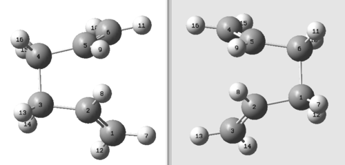
Rep:MM5713TSAR
Introduction
This computational exercise focuses on the study of transition structures within three reactions, the Cope rearrangement of 1,5-hexadiene, the Diels Alder cycloaddition of s-cis butadiene and ethene and the Diels Alder cycloaddition of cyclohexa-1,3-diene with maleic anhydride. The aims of this experiment include:
- locating the transition structures of the various reactions by examining the local shape of the potential energy surface
- determining the structural conformation of the transition structures including their point groups
- calculating the activation energies for the various reaction paths at 0 K and 298.15 K
These outcomes will be determined by numerically solving the Schrodinger equation (shown below) and applying the Born-Oppenheimer approximation, which allows separating the wavefunction into its electronic and nuclear components.
The three levels of theory under which the calculations will be performed are: HF/3-21G, B3LYP/6-31G* or the AM1 semi-empirical level of theory.
The Cope Rearrangement
Introduction
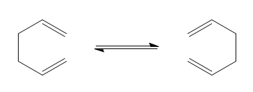
This section of the computational exercise focuses on the Cope rearrangement of 1,5-hexadiene to form a rearranged 1,5-hexadiene product, according to the reaction scheme below.
The Cope rearrangement is part of a class of reactions known as [3,3]-sigmatropic rearrangements, which are characterized by the net shift of one σ-bond from one position to another. These [3,3]-sigmatropic rearrangements form part of a wider set of chemical reactions known as pericyclic reactions. Pericyclic reactions are defined as reactions in which bonds are made or broken in a concerted fashion and proceed across a cyclic transition state. The Cope-rearrangement of 1,5-hexadiene will thus also proceed across a cyclic transition structure than can either assume a "chair" or "boat" conformation. This section of the study will thus focus on the determining the lowest energy conformer of 1,5-hexadiene, as well as calculating the energies of the boat and chair transition structures in order to determine the preferred reaction pathway.
Optimizing the Reactants and Products
Optimization of 1,5-Hexadiene with an Antiperiplanar Conformation of the Four Central C Atoms
Starting from a molecule of 1,5-hexadiene with an antiperiplanar conformation of the four central carbon atoms (i.e. a dihedral angle of 180° between the central four carbon atoms), the structure of 1,5-hexadiene was optimized by employing an HF/3-21G level of theory. The letters 'HF' stand for Hartree-Fock, this means that this level of theory solves the time-independent Schrodinger equation for the many-electron molecule under consideration (1,5-hexadiene) by introducing the Hartree-Fock approximation. This approximation introduces non-linearity within the Schrodinger equation, thus allowing to solve the resulting equation by employing an iterative method. The term '3-21G' instead stands for the chosen basis set, i.e. the set of functions (basis functions) that are combined by linear combination in order to generate the molecular orbitals. In this case, the '3-21G' basis set is a type of split-valence basis set, in which the inner-shell electrons are described by a single Slater orbital, whilst the electrons in the valence orbitals are described by a double-zeta basis set. This approach is very convenient within these calculations, since the inner-shell electrons do not contribute as much to the calculations as the valence electrons, hence maintaining a high level of accuracy of the calculations, whilst also minimizing the time expense.
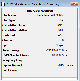
The energy of the 1,5-hexadiene molecule optimised at the HF/3-21G level of theory, was then extracted by accessing the checkpoint (chk) file of the optimized molecule, opening the 'Results' menu and subsequently selecting the 'Summary' button. The optimized structure of the antiperiplanar conformer and its associated energy are shown in the table below. (log file)
Nf710 (talk) 15:27, 10 February 2016 (UTC)the energy of the HF equation is determined by the variation principle which is an iterative method. Good undertsanding of the basis sets!
| Structure | Calculation Summary | Point Group | ||
|---|---|---|---|---|
|
C2 |
From the above table, it followed that the total energy of the conformer was -231.692602 a.u. (Note: the last two significant figures of the computed energy have been removed since these are usually affected by background noise within the calculations).
The symmetry of the conformer was subsequently established by opening the 'Edit' menu and then selecting the 'Point Group...' option. The anti conformer was then approximated to higher-order point groups by setting a tolerance level of '0.01 (default)', which showed that the anti conformer had a C2 point group.
Optimization of 1,5-Hexadiene with a Gauche Conformation of the Four Central C Atoms
The next drawn conformer of the 1,5-hexadiene molecule possessed a gauche conformation of the four central carbon atoms (i.e. a dihedral angle of 60° between the central four carbon atoms). This structure was optimized in the same way as the one in the previous section.
It was expected that the gauche conformer had a higher energy than the previously optimized anti conformer, due to increased destabilizing steric interactions between the alkyl substituents in the gauche conformer.
| Structure | Calculation Summary | Point Group | ||
|---|---|---|---|---|
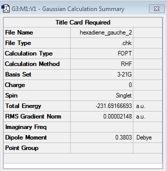
|
C2 |
This hypothesis was confirmed by the results shown in the table above, which demonstrate that the energy obtained for the gauche conformer (log file) at the HF/3-21G level of theory was -231.691667 a.u. (c.f. energy of anti conformer: -231.692602 a.u.). The energy difference between the two conformers was thus calculated to be 0.000935, which corresponds to 0.587 kcal/mol. Similarly to the previous section the point group was established by the same methodology and was found to be C2.
Optimization of the Lowest Energy Conformer of 1,5-Hexadiene
Following the rationale by which the energy difference between the gauche and the anti conformers was explained in the previous section (a purely steric argument), it was expected that the already optimized anti conformer was the lowest energy conformer of the 1,5-hexadiene molecule. Nevertheless, optimization of the gauche3 conformer at the HF/3-21G level of theory (log file), illustrated that the gauche3 conformer of the 1,5-hexadiene molecule was the lowest energy conformer, with an energy of -231.692661 a.u. (c.f. energy of anti1 conformer -231.692602 a.u.).
| Structure | Calculation Summary | Point Group | ||
|---|---|---|---|---|

|
C1 |
These findings agreed with the ones already reported by Fouch [1], who also reported the gauche3 rotamer to be the lowest energy conformer of 1,5-hexadiene. This can be rationalized by analyzing the HOMO of the gauche3 conformer. The HOMO of the gauche3 conformer, see above, illustrates two stabilizing stereoelectronic interactions. One of these stabilizing interactions results from the the in-phase orbital overlap of the two π-systems that reside on C1-C4 and C12-C14, hence resulting in a favorable secondary orbital interaction. The other stabilizing interaction instead can be attributed to the in-phase orbital overlap of the π-orbital on C12, with the adjacent vinyl proton.
Identification of Antiperiplanar and Gauche Conformers
The optimized structures of the antiperiplanar and gauche conformers calculated within the first two sections were identified by comparing the calculated energies and point groups with the ones of the conformers provided. This revealed that the optimized antiperiplanar (-231.692602 a.u. and C2 point group) and gauche conformer (-231.691667 a.u. and C2 point group) corresponded to the anti1 and gauche2 conformer respectively.
Anti2 Conformer of the 1,5-Hexadiene Molecule
The anti2 conformer was also optimized at the HF/3-21G level of theory (log file) and its structure can be found in the table below. The energy computed for the anti2 conformer was -231.692535 a.u. and its symmetry was found to be Ci.
| Structure | Calculation Summary | Point Group | ||
|---|---|---|---|---|
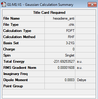
|
Ci |
Comparing the energy of the computed anti2 conformer (-231.692535 a.u.) with the anti2 conformer presented in literature (-231.69254 a.u.) demonstrated that the energy obtained for the computed anti2 conformer was identical to the one given in 'Appendix1', when taking into account the rounding of the last significant figure. Moreover the two figures also featured the same point group, hence being further proof for having computed the correct anti2 conformer.
Anti2 Conformer Optimization at the B3LYP/6-31G* Level of Theory
Having optimized the structure of the anti2 conformer at the HF/3-21G level of theory, the structure of the anti2 conformer was reoptimized at the B3LYP/6-31G* level. Employing a B3LYP/6-31G* level of theory, implies calculating the properties of 1,5-hexadiene by a density functional theory (DFT) method. The DFT method derives the properties of 1,5-hexadiene from the electron density of the 1,5-hexadiene molecule and thus differs from the HF method, which derives the properties of the molecule from the wavefunction itself. An advantage of using the DFT method over the HF method is that the DFT method allows for more time-efficient ground state calculations, hence reducing the time expense of the computations.
Nf710 (talk) 15:33, 10 February 2016 (UTC) Good! DFT is not actually as accurate as HF. You are just using a higher basis set here. They also have completely different hamiltonians as you have said, and therefore cannot be compared. unless you compare relative energies.
The optimization of the anti2 conformer at the B3LYP/6-31G* level (log file) was performed by selecting 'DFT' under the 'Method' menu and 'B3LYP' from the box of functionals on the right-hand side. The structural and energetic results of the computation are shown below.
| Structure | Calculation Summary | Point Group | ||
|---|---|---|---|---|

|
Ci |
The energy obtained for the B3LYP/6-31G* optimized anti2 conformer was -234.611712 a.u..
The table beneath compares the geometry of the B3LYP/6-31G* optimized anti2 conformer with the geometry of the HF/3-21G optimized anti2 conformer. As the anti2 conformer displays a Ci symmetry, the bond distances and bond angles of only one side (C1-C2-C3) of the molecule have been taken into consideration, as these should be identical to the ones on the opposite side (C4-C5-C6).
| Level of Theory | C1-C2 bond length [Å] | C2-C3 bond length [Å] | C3-C4 bond length [Å] | C1-C2-C3 bond angle [°] | C2-C3-C4 bond angle [°] | C1-C2-C3-C4 dihedral angle [°] |
|---|---|---|---|---|---|---|
| HF/3-21G | 1.31614 | 1.50887 | 1.55290 | 124.814 | 111.344 | 179.998 |
| B3LYP/6-31G* | 1.33350 | 1.50420 | 1.54816 | 125.299 | 112.671 | 180.000 |
Comparing the results obtained for the geometry of the anti2 conformer at the two different levels of theory (HF/3-21G and B3LYP/6-31G*) illustrated that the values obtained for the bond distances, bond angles and dihedral angles were similar to each other, however still displayed some minor differences. Consequently, the overall geometry between the HF/3-21G and the B3LYP/6-31G* optimized structure for the anti2 conformer only differed by a small extent. Nevertheless, although the overall geometry between the HF/3-21G and the B3LYP/6-31G* optimized structure of the anti2 conformer differed slightly, the point group for either structure remained unchanged (Ci), since the changes in geometry on one side of the conformer were also reflected on the other side.
Frequency Calculation of the Anti2 Conformer at the B3LYP level of theory
Commencing from the optimized B3LYP/6-31G* structure of the anti2 conformer the frequency calculation was carried out by choosing the option 'Frequency' under the 'Job Type' section of the Gaussian Calculation Setup. The level of theory chosen was once again the B3LYP/6-31G* level. Rather than opening the .chk file of the calculations performed, the log file (log file) was opened in order to visualize the vibrational frequencies and modes of the anti2 conformer. These were accessed by selecting the 'Vibrations' option under the 'Results' menu. The vibrational modes and frequencies obtained for the anti2 conformer are summarized in the figure below.
The above figure illustrates that there were no imaginary frequencies, i.e. frequencies with a negative wavenumber value. This was indicative that the anti2 conformer was indeed a minimum point on the potential energy surface.
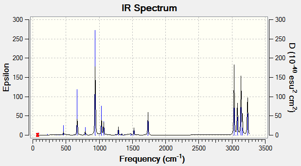
The simulated IR spectrum of the B3LYP/6-31G* optimized anti2 conformer is shown in the figure below.
The various energies of the optimized B3LYP/6-31G* structure were extracted by first accessing the 'Summary...' option under the 'Results' menu, followed by then clicking 'View File' and searching for the 'Thermochemistry' section.
The energies calculated and extracted for the anti2 conformer were:
- 1. Sum of electronic and zero-point energies = -234.469215 a.u.
The sum of the electronic and zero-point energies stands for the potential energy at 0 K including the zero-point vibrational energy
- 2. Sum of electronic and thermal energies = -234.461866 a.u.
The sum of the electronic and thermal energies corresponds to the energy at 298.15 K and 1 atm. This sum of energies takes into account contributions from the translational, rotational and vibrational modes at 298.15 K.
- 3. Sum of electronic and thermal enthalpies = -234.460922 a.u.
The sum of the electronic and thermal enthalpies is instead the sum of the sum of the electronic and thermal energies with an additional correction for RT
- 4. Sum of electronic and thermal free energies = -234.500800 a.u.
The sum of electronic and thermal free energies is equal to the sum of the sum of electronic and thermal enthalpies and the entropic contribution to the free energy.
Mathematically, these four energies correspond to E = Eelec+ZPE, E = E+Evib+Erot+Etrans, H = E=RT and G = H-TS respectively.
Optimizing the "Chair" and "Boat" Transition Structures
Optimization of the Allyl Fragment at the HF/3-21G Level of Theory
Having drawn an allyl fragment in Gaussview, the structure of the allyl fragment was optimized by using the HF/3-21G level of theory (log file). The optimized structure and calculation summary are shown below.
| Structure | Calculation Summary | Point Group | ||
|---|---|---|---|---|
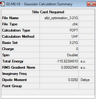
|
C2v |
The optimized structure was then used as a template for the construction of the chair and boat transition structures. Beginning with the chair transition structure the process was as follows. The optimized allyl fragment structure was copied by selecting the 'Copy' button under the 'Edit' menu. A new window was then opened and the optimized allyl structure was pasted twice. The two fragments were then translated and rotated into a conformation that resembled the chair transition state. It was also ensured that the distance between the terminal ends of the allyl fragements was approximately 2.2 Å.
Optimization of the Chair Transition Structure by Computing the Hessian
Within this section of the computational experiment, the chair transition structure was optimized by computing the force constant matrix (the Hessian), which was then updated as the optimization proceeded. This method involved carrying out the following steps. Having opened the 'guessed' chair transition structure created within the previous passage an 'Opt+Freq' job type was selected. This type of job involved optimizing the 'guessed' chair transition structure as well as performing a frequency calculation. Moreover, as the aim of this optimization was to optimize a transition structure, it was necessary to change the option optimize to a 'Minimum' to optimize to a 'TS(Berny)'. Additionally, it was selected to only calculate the force constants 'Once' and the keyword 'Opt=NoEigen' was added to the box of additional keyboards. This keyword was employed in order to prevent the computation to crash if more than one imaginary frequency is detected during the optimization. Lastly, it was ensured that the HF/3-21G level of theory was employed as calculation method. The optimized chair transition structure (log file) with its calculation summary is shown below.
| Structure | Calculation Summary | Point Group | ||
|---|---|---|---|---|
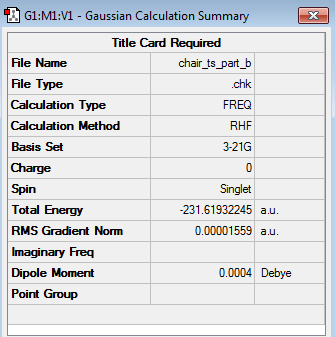
|
C2h |
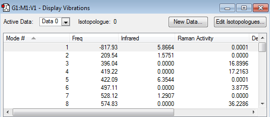
The frequency calculation in the table below, illustrated that the optimized transition state structure possessed only one imaginary frequency occurring at -817.93 cm-1. This was indicative that the transition structure had indeed been optimized to a transition structure and not to a stable intermediate/reactant/product. The reason why obtaining a single imaginary frequency was proof for having obtained a transition state structure can be explained mathematically.
Consider how the energy of a molecule changes with respect to the nuclear position (x). The first derivative of the energy with respect to the nuclear position is given by:
This derivative must be zero for a minimum in the potential energy surface (such as a stable reactant/intermediate/product) and a saddle point in the potential energy surface (such as a transition structure). Consequently, in order to distinguish between the two structures it is necessary to take the second derivative of the energy with respect to the nuclear position (x):
For a minimum point in the potential energy surface (such as a stable reactant/intermediate/product), the second derivative will only yield positive values. On the other hand for a saddle point in the potential energy surface (such as a transition structure), the second derivative will yield a range of positive values, but also one negative value.
Since the second derivative of the energy with respect to the nuclear position is also equal to the force constant (k), it follows that:
This can then be related to the vibrational frequency of a harmonic oscillator through the expression:
Consequently, a transition structure will always feature an imaginary frequency for one vibrational mode, which corresponds to the vibrational mode with the negative k value.
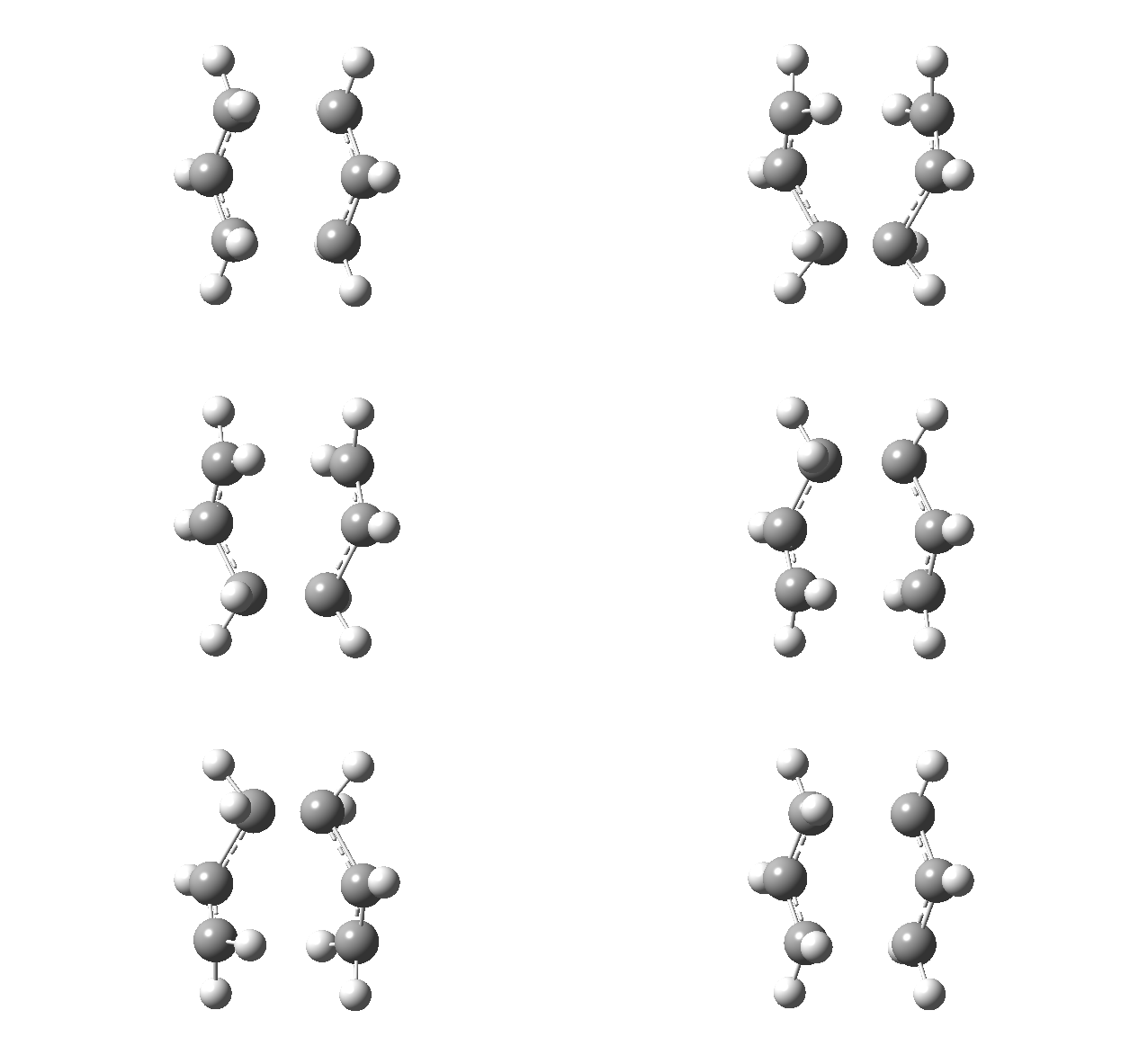
Animating the imaginary frequency (-817.93 cm-1) obtained for the optimized chair transition structure showed that this vibrational mode involved the terminal ends of the two allyl fragments oscillating towards and away from each each other, hence correspond to the vibration associated to the Cope rearrangement.
Nf710 (talk) 15:43, 10 February 2016 (UTC) this is very nicely formatted.
| Vibrational Calculation | Imaginary Frequency Animation |
|---|---|
|
|
Optimization of the Chair Transition Structure by Employing the Frozen Coordinate Method
Utilizing the same 'guess' chair transition structure as in the section 'Optimization of the Chair Transition Structure by Computing the Hessian', this method of optimizing the chair transition structure involved to initially freeze the reaction coordinate and optimize the structure of the molecule. When the structure of the molecule was minimized the reaction coordinate was then unfrozen and the transition state optimization was performed once more. The individual steps of this method are as follows.
Beginning from the 'guess' chair transition structure, the reaction coordinates were frozen by first clicking the 'Edit' button and selecting the option 'Redundant Coordinate ...'. This opened the redundant coordinate editor, which featured the button 'Create a New Coordinate' in the top left-hand corner. Clicking on the button caused a line to appear stating: 'Add Unidentified (?, ?, ?, ?)'. Switching back to the GaussView window in which the 'guess' transition structure resided, two of the terminal carbon atoms that would form/break a bond during the Cope rearrangement were selected and the options 'Unidentified' and 'Add' were changed to 'Bond' and 'Freeze Coordinate' respectively. This procedure was repeated for the terminal carbon atoms on the opposite end of the allyl fragments. Once the coordinates for the selected atoms were frozen, the structure was optimized to a minimum at the HF/3-21G level of theory (log file). The optimized structure is shown below.
A comparison between the optimized chair transition structure with frozen coordinates and the chair transition structure optimized by solving the Hessian, illustrated that the two structures closely resembled each other, except for the bond forming/breaking distances that werer set to 2.2 Å in the frozen coordinate transition structure.
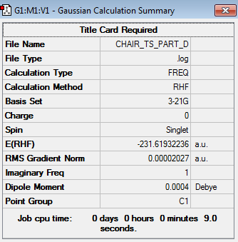
Having optimized the entire chair transition structure, except for the bond forming/breaking distances between the terminal carbon atoms on the allyl fragments, it was necessary to also optimize these in order to obtain a 'completely' optimized chair transition structure. Similarly to the method described previously, the bond forming/breaking distances were optimized by also utilizing the frozen coordinate method. This involved opening the chk file of the optimized chair transition structure with the frozen coordinates and once again accessing the redundant coordinate editor by selecting the option 'Redundant Coordinates...' in the 'Edit' menu. The same combination of atoms was selected as in the previous section. This time however, the options 'Bond' and 'Derivative' were selected. Having carried out this process for both combinations of atoms, the structure was then optimized to a transition state at the HF/3-21G level of theory, by selecting the option 'Optimize to a TS(Berny)' under the 'Job Type' menu. Moreover, it was also necessary to change the option to calculate the force constants from 'Once' to 'Never'. The 'completely' optimized chair transition structure obtained from this optimization is shown below (log file).
| Structure | Calculation Summary | Point Group | ||
|---|---|---|---|---|
|
C2h |
To prove that this was indeed a transition structure, the results from the frequency calculation were examined. These revealed the presence of a single imaginary frequency at -817.88 cm-1, thus meaning that the above structure was indeed a transition state structure. The vibrational mode of the imaginary frequency is shown below and was attributed to the Cope rearrangement of 1,5-hexadiene.
| Vibrational Calculation | Imaginary Frequency Animation |
|---|---|

|

|
Comparing the optimized structure of the chair transition state that was computed from the frozen coordinate method with the one that was constructed by solving the Hessian, showed that these resembled each other very closely. In fact, this was confirmed by comparing the bond forming/breaking lengths obtained for the two structures, see table below.
| Optimized Chair TS by Computing the Hessian | Optimized Chair TS by Frozen Coordinate Method | |
|---|---|---|
| C3-C14 interatomic distance [Å] | 2.02028 | 2.02071 |
| C6-C11 interatomic distance [Å] | 2.02048 | 2.02076 |
The results in the table above illustrate that the bond forming/breaking distances obtained for the two structures were very similar to each other and were effectively identical. This demonstrates that either method (solving the Hessian or freezing the reaction coordinates) leads to the same chair transition structure. This idea was further supported by the energies obtained for the optimized chair transition structures by the two different methods. Whilst the energy of the optimized chair transition structure computed by solving the Hessian was found to be -231.61932245 a.u., the energy of the optimized chair transition structure calculated by solving the frozen coordinate method amounted to -231.61932236 a.u., thus highlighting once more the similarity between the two structures.
Optimization of the Boat Transition Structure by the QST2 Method
This section of the computational exercise focuses on optimizing the boat transition structure of the Cope Rearrangement by utilizing the QST2 method. The QST2 method differs from the previous method, since this method interpolates the structure of the transition state by starting from the structure of the reactants and products. Although the Cope rearrangement of 1,5-hexadiene still yields a 1,5-hexadiene product, the distribution of the single and double bonds between the specific atoms is different between the starting and final 1,5-hexadiene structure. It is therefore necessary to correctly label the individual atoms, so that the numbering of the product 1,5-hexadiene molecule corresponds to the numbering obtained if the reactant 1,5-hexadiene molecule had rearranged.
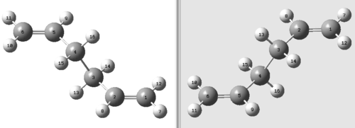
This process was carried out by first opening the chk file of the optimized anti2 structure and copying the structure into a new window. This new window was now added to a 'MolGroup' by selecting the 'File' menu, then clicking on 'New' and finally 'Add to MolGroup'. This generated three new icons in the left-hand corner of the window: one featuring a green circle, one featuring a field to input numbers (which could also be changed by pressing the two arrow buttons adjacent to the icon) and one featuring two molecules side by side. Moreover, selecting the option 'Add to MolGroup' also caused the structure of the reactant molecule to disappear. To re-access the original structure the number in the second icon was simply changed from '2' to '1'. Changing the number from '1' back to '2' then allowed to access the empty window again. Pasting the structure of the optimized anti2 structure into this empty window effectively allowed to paste the structure of the product molecule, i.e. the structure of the rearranged 1,5-hexadiene molecule. The reactant and product structure were then opened side by side by clicking the third button in the top-left corner. In order to see the atomic numbering on both structures, the 'Labels' option in the 'View' menu was selected. The atomic numbering of the reactant and product structure are shown in the figure below.
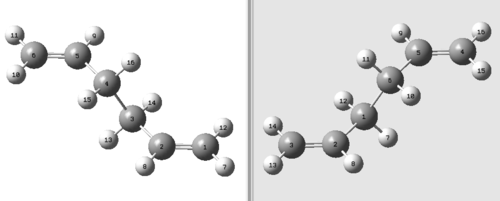
From the figure above it followed that the atomic labeling on the product structure did not correspond to the atomic labeling of the rearranged reagent structure. Consequently, it was necessary to change the atomic labeling on the product structure in order to match the atomic labeling of the rearranged reactant structure. The atomic labeling on the product structure was changed by opening the 'Edit' menu and selecting the button 'Atom List'. This opened the 'Atom List Editor' in which it was possible to select the various atoms on the product structure and change them to the desired ones by simply inputting the desired number into the 'Tag' field. The correct atomic labeling of the product structure to match the one of the rearranged reactant structure is shown in the figure below.
The boat transition structure was then determined by carrying out an Optimization and Frequency ('Opt+Freq') calculation on the correctly labeled structures. Moreover, contrary to the previous transition structure optimization calculations, this time the transition structure was not optimized to a 'TS(Berny)', but to a 'TS(QST2)'. Lastly, the level of theory chosen was once more the HF/3-21G level of theory. The resulting optimized structure is shown below (log file).
From the above figure it can be seen that the optimized structure does not resemble the desired boat transition structure, but instead the chair transition structure. The reason for having computed this incorrect transition structure is because the computation simply translated the top allyl fragment, hence resulting in a transition structure that attempts the formation/breaking of bonds that cross each other.
It was thus necessary to adjust the dihedral angle between the atoms C2-C3-C4-C5 from 179.998° to 0° and the bond angles between the atoms C2-C3-C4 and C3-C4-C5 from 111.352° to 100° in both reactant and product 1,5-hexadiene. The resulting conformation of the reactant and the product structure are displayed in the figure below.
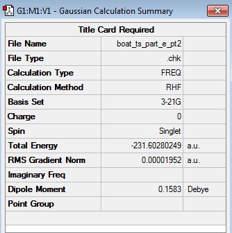
The transition structure optimization was then run once again, with the same specifications as previously ('Job Type' = 'Opt+Freq', Optimize to a 'TS(QST2)' and at the HF/3-21G level of theory). The optimized boat transition state structure (log file) is shown in the table below alongside its calculation summary.
| Structure | Calculation Summary | Point Group | ||
|---|---|---|---|---|
|
C2v |
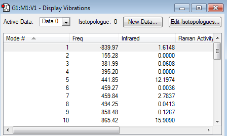
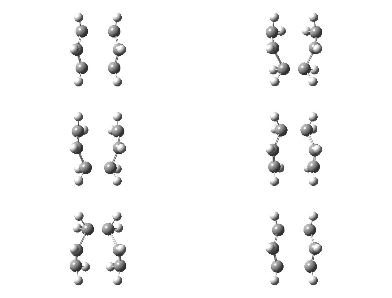
The above table illustrates that the boat transition structure had now been optimized correctly, as it truly resembled a boat transition structure. Moreover, the presence of a single imaginary frequency at -839.97 cm-1 for the optimized boat transition structure, confirmed that the optimized structure corresponded indeed to a transition structure. The animation of this imaginary frequency demonstrated that this frequency corresponds to the Cope rearrangement.
| Vibrational Calculation | Imaginary Frequency Animation |
|---|---|
|
|
Comparing the energy of the optimized chair transition structure (-231.61932236 a.u.) with the energy of the optimized boat transition structure (-231.60280249 a.u.) showed that the boat transition structure was significantly higher in energy (0.01651987 a.u. = 10.37 kcal/mol) than the chair transition structure. This is because the boat conformation is destabilized by torsional strain and steric strain as a result of the interactions between the flagpole hydrogens.
Nf710 (talk) 15:47, 10 February 2016 (UTC) your energies and frequcies are correct and clearly explained
Determination of the Conformer formed from the Chair Transition Structure by the Intrinsic Reaction Coordinate Method
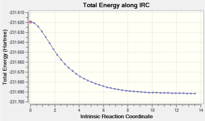
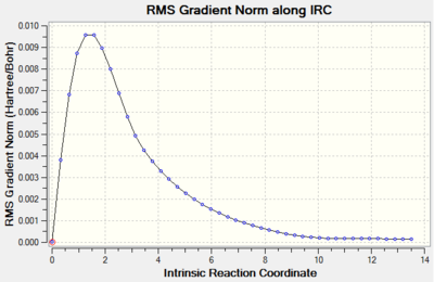
The Intrinsic Reaction Coordinate Method (IRC) was employed to determine the product conformer formed from the chair transition state. The IRC method operates by following the minimum energy path from a transition structure towards the local minimum on a potential energy surface. This is achieved by following the steepest energy gradient on the potential energy surface. The IRC calculation was performed by first opening the chk file of the chair transition structure that had been optimized by solving the Hessian. The actual IRC calculation was performed by selecting the option 'IRC' under the 'Job Type' tab and then setting the 'Follow IRC' option to 'Forward Only', since the reaction coordinate for the Cope rearrangement is symmetrical. The option to calculate the force constants was then set to 'Calculate Always' and the option for the number of points considered along the IRC was changed from '6' to '50'. Lastly, the level of theory at which the calculations were performed was set once more to the HF/3-21G level of theory. The calculations' output (log file) is shown in the table below.
| IRC Calculation | Total Energy along IRC against Intrinsic Reaction Coordinate Plot | RMS Gradient Norm along IRC against Intrinsic Reaction Coordinate Plot |
|---|---|---|

|
|
|
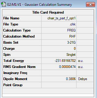
The 'Total Energy along IRC' plot illustrated that the energy of the transition structure was converging towards a minimum as the reaction coordinate increased. Nevertheless, the 'RMS Gradient NORM along IRC' plot demonstrated that the gradient obtained for the final structure (0.00015224 a.u.) did not assume a value of zero yet. This was indicative of the fact that the final structure did not reach a minimum geometry yet and a further minimization had to be carried out. The minimization of the final structure was performed by opening the chk file of the final geometry of the IRC and then selecting the options 'Optimization' as the 'Job Type' and the HF/3-21G level of theory as 'Method'. The outcomes of this optimization (log file) are illustrated below.
| Structure | Calculation Summary | Point Group | ||
|---|---|---|---|---|
|
C2 |
The calculations' summary shown in the table above demonstrated that the gradient of the HF/3-21G optimized final structure possessed an RMS gradient of 0.00000474 a.u. (c.f. RMS gradient of final structure along IRC = 0.00015224 a.u.) and a total energy of -231.691667 a.u. (c.f. Total energy of final structure along IRC = -231.691579 a.u.), hence meaning that the optimization had been carried out successfully. Furthermore, the point group of the optimized structure was found to be C2, hence meaning that the optimized conformer of the product 1,5-hexadiene molecule corresponds to the gauche2 conformer of 1,5-hexadiene.
Nf710 (talk) 15:50, 10 February 2016 (UTC) correct conformer identified
Activation Energy Calculation for the Cope Rearrangement across the Chair and Boat Transition Structures
Before calculating the activation energies for the Cope rearrangement of 1,5-hexadiene across the chair and boat transition structures, the chair and boat transition structures were reoptimized at the B3LYP/6-31G* level of theory alongside carrying out frequency calculations. The structures of the chair and boat transition structures were reoptimized by opening the respective chk file of the HF/3-21G optimized structures. The HF/3-21G optimized structures were optimized to the B3LYP/6-31G* level of theory by selecting the 'Opt+Freq' option as the 'Job Type' and the B3LYP/6-31G* level of theory as the 'Method'. The results obtained for the reoptimized chair (log file) and boat (log file) transition structures can be accessed below.
| Transition State Conformation | Structure | Calculation Summary | Vibrational Calculations | Point Group | ||
|---|---|---|---|---|---|---|
| Chair | 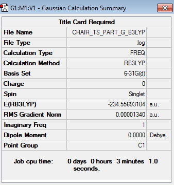
|

|
C2h | |||
| Boat | 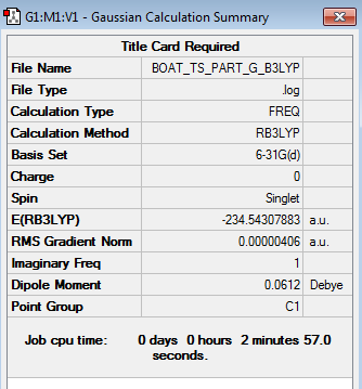
|

|
C2v |
The above table demonstrates that the energies obtained for the chair and boat TS at the B3LYP level of theory were -234.556931 a.u. and -234.543079 a.u. respectively. The vibrational calculations display that only one imaginary frequency was obtained for either TS (-569.31 cm-1 for chair TS and -532.18cm-1 for boat TS), hence indicating that both optimized TS structures were indeed TS.
A comparison of the geometries of the chair and boat transition state structures optimized at the two different levels of theory (HF/3-21G and B3LYP/6-31G*) is shown in the table below.
| Transition Structure Conformation and Level of Theory | C1-C6 interatomic distance in TS [Å] | C1-C2 interatomic distance in TS [Å] | C1-C2-C3 bond angle in TS [°] |
|---|---|---|---|
| Chair (HF/3-21G) | 2.02048 | 1.38927 | 120.491 |
| Chair (B3LYP/6-31G*) | 1.96669 | 1.40760 | 119.926 |
| Boat (HF/3-21G) | 2.13987 | 1.38146 | 121.680 |
| Boat (B3LYP/6-31G*) | 2.20640 | 1.39327 | 122.250 |
The above table illustrates that although there is a certain degree of discrepancy between the geometries of the chair and boat transition structures at the two levels of theory, the differences in geometry are relatively small. Consequently, the geometries of the two transition structures do not depend strongly on the level of theory chosen. In contrast, the difference in energies between the reactants (anti2 conformer) and the transition states (chair or boat) differs significantly between the two levels of theory, as shown below.
Note: All displayed energy values are given in Hartrees
| HF/3-21G | B3LYP/6-31G* | |||||
|---|---|---|---|---|---|---|
| Electronic Energy | Sum of electronic and zero-point energies at 0 K | Sum of electronic and thermal energies at 298.15 K | Electronic Energy | Sum of electronic and zero-point energies at 0 K | Sum of electronic and thermal energies at 298.15 K | |
| Reactant (anti2) | -231.692535 | -231.539540 | -231.532566 | -234.611712 | -234.469215 | -234.461866 |
| Chair TS | -231.619322 | -231.466699 | -231.461340 | -234.556931 | -234.414908 | -234.408980 |
| Boat TS | -231.602802 | -231.450928 | -231.445299 | -234.543079 | -234.402356 | -234.396012 |
From the above table it followed that employing a different level of theory did not only result in a significant difference (approx. 3 Hartrees) in the absolute energy of the three structures under consideration, but also in a significant difference in the relative energy of the three structures. To determine which one of the two levels of theory employed (HF/3-21G or B3LYP/6-31G*) achieved more accurate results, it was necessary to compare the relative activation energies calculated for the two different levels of theory. The activation energies across both transition structures were calculated at 0 K and 298.15 K by utilizing the sum of electronic and zero-point energies at 0 K and the sum of electronic and thermal energies at 298.15 K respectively.
Note: All displayed energy values are given in kcal/mol
| HF/3-21G at 0 K | HF/3-21G at 298.15 K | B3LYP/6-31G* at 0 K | B3LYP/6-31G* at 298.15 K | Experimental Data [2] at 0 K | |
|---|---|---|---|---|---|
| Eact(Chair) | 45.70 | 44.70 | 34.08 | 33.19 | 33.5 ± 0.5 |
| Eact(Boat) | 55.60 | 54.76 | 41.95 | 41.32 | 44.7 ± 2.0 |
From the results shown above it could be seen that the activation energies at 0 K computed under the B3LYP/6-31G* level of theory resembled more closely the experimental data reported by von Doering compared to the ones calculated under the HF/3-21G level of theory. It thus followed that the B3LYP/6-31G* level of theory produced more accurate results than the HF/3-21G level of theory. Moreover, comparing the activation energy computed at the B3LYP/6-31G* level of theory for a temperature of 0 K with the experimental data demonstrated that the activation energy of the chair conformer was within the experimental range, whilst the activation energy of the boat conformer was marginally outside of the experimental range.
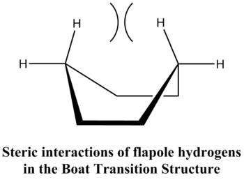
Furthermore, the above table also illustrates that the lower energy pathway for the Cope rearrangement of the anti2 conformer of 1,5-hexadiene proceeds by the chair transition structure and is thus likely to be the preferred pathway for this reaction. The energy difference between the two transition states is approximately 8 kcal/mol. This can be rationalized by the fact that the boat transition structure is destabilized by the eclipsed conformations along C1-C6 & C3-C4 and steric interactions of flagpole hydrogens[3]. These interactions are illustrated below.
Nf710 (talk) 15:54, 10 February 2016 (UTC) this has been a very good report, excellent use of jmols and good knowledge of theory. Everything was clearly explained to the extent that you could possibly have been more concise. well done.
The Diels Alder Cycloaddition
This section of the computational exercise focuses on two Diels Alder Cycloaddition Reactions. The general reaction scheme of a Diels Alder reaction is shown in the figure below.
The Diels Alder Reaction is a [π4+π2] cycloaddition reaction between a conjugated diene with a dienophile, that involves 4 π-electrons of the diene and 2 π-electrons of the dienophile. The mechanism of this reaction involves the σ-overlap of the π-orbitals of the two unsaturated systems.
In contrast to the Cope rearrangement, in which there is no net change in the number of sigma bonds present within the reactants/products, the Diels-Alder reaction proceeds by the formation two new σ-bonds and the cleavage of two π-bonds. The formation of two new σ-bonds in exchange for the loss of two π-bonds ultimately also provides an enthalpic driving force for the reaction to proceed. To determine whether this bond forming process occurs in a concerted stereospecific fashion (allowed) or not (forbidden) it is necessary to analyse the interaction between the HOMO/LUMO orbitals on the diene and the dienophile according to the Woodward-Hoffmann rules [4] which state that:
- If the HOMO of one reactant can interact with the LUMO of the other reactant than the reaction is allowed
- In order for the HOMO of one reactant to interact with the LUMO of the other reactant there must be significant orbital overlap. This can only be achieved when the interacting orbitals have identical symmetry properties.
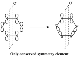
As the only conserved symmetry element within the Diels Alder reaction is the mirror plane that runs through the center of the reactants, the symmetry of the interacting orbitals is classified with respect to that mirror plane. If the molecular orbital under consideration is symmetric with respect to the reflection plane it is classified as s, instead if the molecular orbital under consideration is antisymmetric, it is classified as a.
(Very good introduction. Aside from that, in the images only the last size tag is read. Specifying width and height won't change the ratio Tam10 (talk) 10:34, 1 February 2016 (UTC))
Diels Alder Cycloaddition of s-cis Butadiene with Ethene
Optimization of s-cis Butadiene and Ethene
Having built the structures of s-cis butadiene and ethene in separate windows of Gaussview, the structure of each component was optimized at the AM1 semi-empirical molecular orbital method. (log file for s-cis butadiene) (log file for ethene)
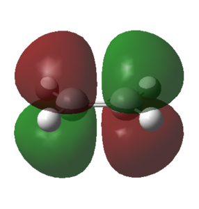
To determine the symmetry of the HOMO and LUMO with resepct to the symmetry plane for each component it was necessary to select 'Edit' and then the option 'MOs'. The HOMO and LUMO from the MO list were then selected and constructed by clicking the buttons 'Visualise' and then 'Update'. The calculated HOMO and LUMO for the ethene reactant are shown in the table below.
| HOMO | LUMO | |
|---|---|---|
| Orbital representation | 
|
|
| Symmetry | s | a |
From the above table it followed that the HOMO of ethene was symmetric and the LUMO of ethene anti-symmetric with respect to the plane of symmetry that runs through the center of the molecule.
The calculated HOMO and LUMO for s-cis butadiene are shown in the table below.
| HOMO | LUMO | |
|---|---|---|
| Orbital representation | 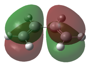
|

|
| Symmetry | a | s |
The table above illustrated that the HOMO of the s-cis butadiene molecule was anti-symmetric with respect to the plane of symmetry and the LUMO of the s-cis butadiene was symmetric. From the symmetry analysis of the HOMO and the LUMO orbitals of the s-cis butadiene and the ethene fragment it followed that there were only two allowed interactions between the various orbitals, namely the interaction between:
- the HOMO of butadiene (a) and the LUMO of ethene (a)
- the LUMO of butadiene (s) and the HOMO of ethene (s).
Computation of the Transition State Geometry and Examination of the Nature of the Reaction Path
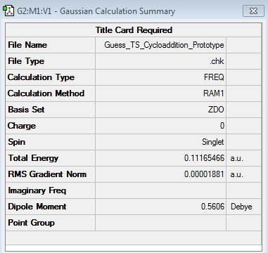
The transition structure for the considered Diels Alder reaction assumed an envelope like structure, which maximizes the orbital overlap between the conjugated π-system of butadiene and the π-system of ethene. In order to obtain the necessary starting geometry for the structural determination of the transition state it was necessary to first construct a bicyclooctene structure, followed by the removal of the -CH2-CH2- bridge. The interfragment distance between the ethene and the s-cis butadiene fragment was then set to 2.2 Å, as Tia et al. [5] have determined that this was the bond length of the forming σ C-C bonds in the transition structure. This structure was then optimized to a transition structure by selecting the option 'Opt+Freq' as 'Job Type', then choosing the options to optimize to a 'TS (Berny)', calculating the force constants 'Once', adding the additional keyword 'Opt=NoEigen' and lastly selecting the AM1 semi-empirical method as 'Method'. The resulting transition state structure is shown below. (log file)
| Structure | Calculation Summary | Vibrational Calculations | ||
|---|---|---|---|---|
|
|
From the above geometry it followed that the C=C bond lengths between the atoms C1-C2, C3-C4 and C7-C10 had already increased to a value of 1.38 Å, thus being longer than a typical C=C double bond (1.34 Å), but shorter than a typical C-C single bond (1.54 Å). This indicated that the 6π electrons involved in the cycloaddition reaction were effectively delocalised over the positions of the previously mentioned carbon atoms. The above geometry also demonstrated that the bond-lengths of the partially formed σ C-C bonds corresponded to 2.12 Å. These bond-lengths were longer than those of typical sp3 C-C bond lengths (1.54 Å). However, in comparison to the sum of the van der Waals radii [6] of two carbon atoms (3.40 Å), the bond-lengths of the two partially formed σ C-C bonds in the transition structure were significantly shorter. This illustrated that in the transition structure there was already a strong degree of primary orbital interaction between terminal carbon atoms on butadiene and ethene, hence accounting for the reduced internuclear distance of the partially formed σ C-C bonds.
(Good geometry analysis. Tam10 (talk) 10:34, 1 February 2016 (UTC))
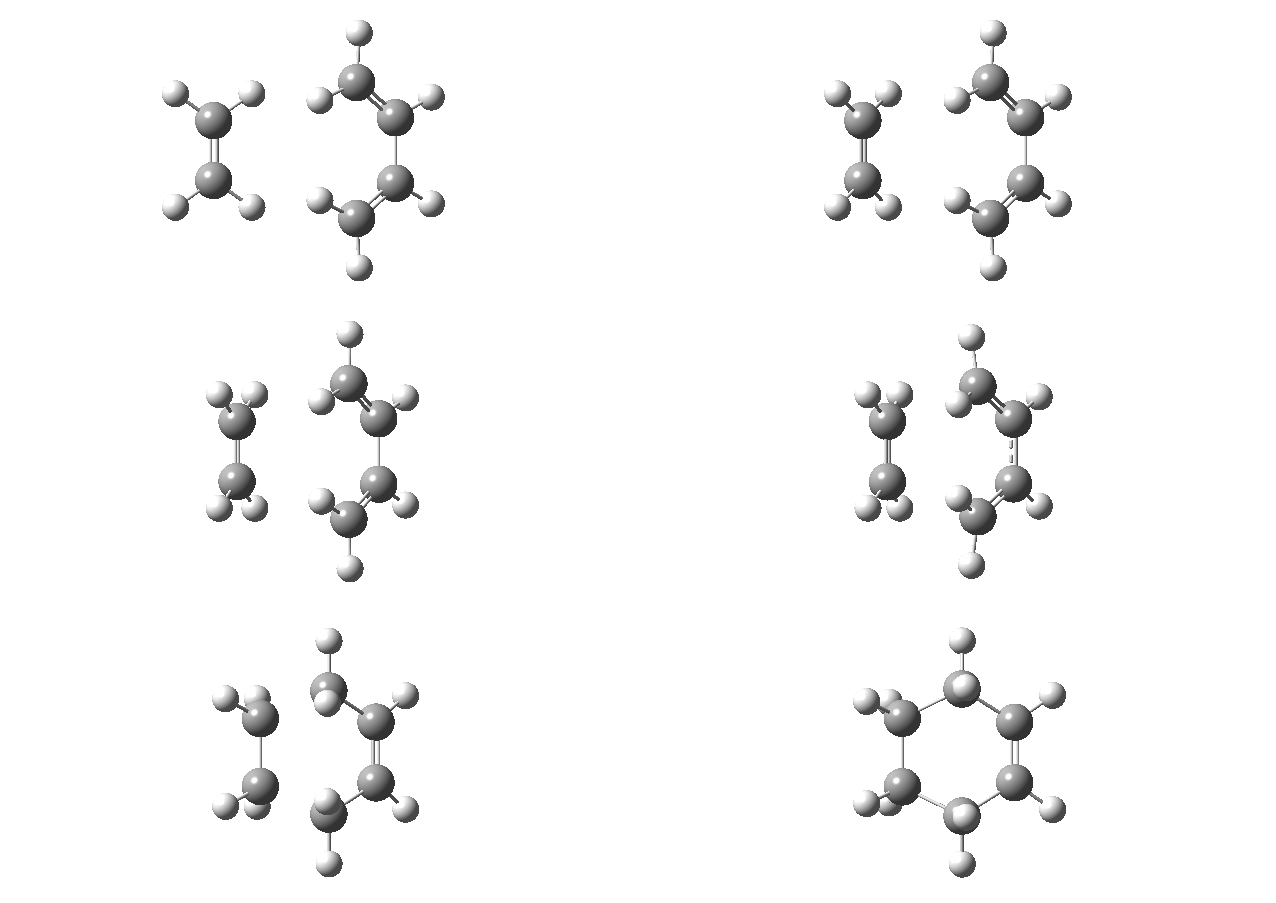
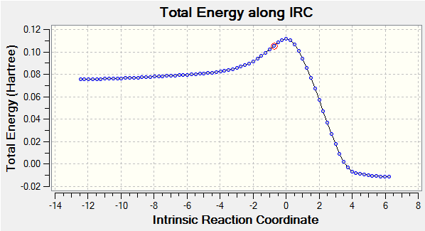
Moreover, as the partially formed σ C-C bonds (C2-C7 and C3-C10) featured equal lengths (2.12 Å) in the computed transition structure, this was an indication that the bond forming process occurred in a synchronous fashion. This hypothesis was further confirmed by analyzing the calculated IRC (log file), shown below, which clearly illustrates the concerted C-C bond formation.
| IRC Animation | Total Energy along IRC Plot |
|---|---|
|
|
This hypothesis of a synchronous bond formation process also agreed with the findings reported by Bach et al[7].. Furthermore, the 'Total Energy along IRC' plot also demonstrated that according to Hammond's postulate the transition state structure in the cycloaddition of butadiene and ethene is an early tranisition state structure, as the energy of the transition structure resembled the energy of the reactants more closely than the energy of the products.
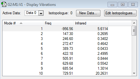
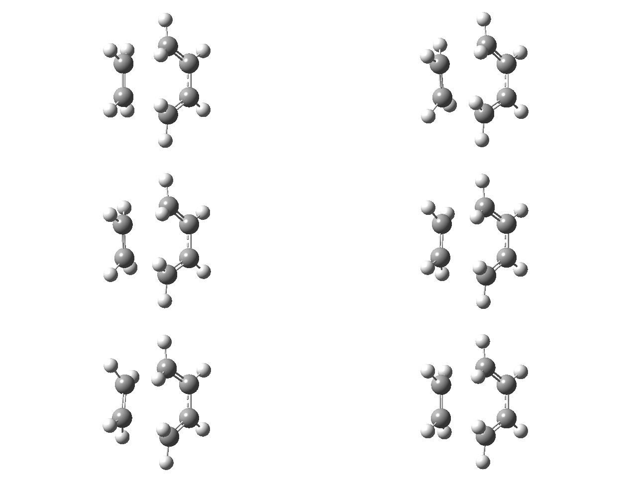
The frequency calculation also highlighted that only one imaginary frequency was obtained for the computed transition structure, namely at -956.56 cm-1. This was indicative of the fact that the optimized transition structure was indeed a transition structure. The vibrational mode of the imaginary frequency and the lowest positive frequency are shown below.
| Vibrational Mode | Imaginary Frequency | Lowest Positive Frequency |
|---|---|---|
| Animation | 
|
|
The animation of the imaginary frequency illustrates that the vibrational mode of the imaginary frequency featured the oscillation of the terminal ends of butadiene and ethene towards and away from each other, thus corresponding to the vibration associated to the Diels Alder cycloaddition reaction. Moreover the vibrational mode of the imaginary frequency also showed that the formation of the two σ C-C bonds was synchronous. This behavior was contrasted by the vibrational mode of the lowest positive frequency, which corresponded to an asynchronous wag of the molecule.
| HOMO | LUMO | |
|---|---|---|
| Orbital representation | 
|
|
| Symmetry | a | s |
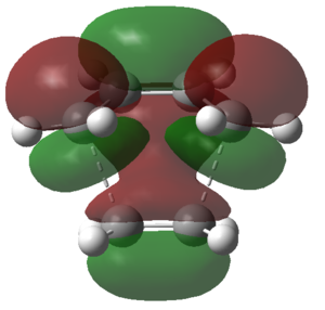
From the above table it followed that the HOMO at the transition structure was antisymmetric with respect to the plane of symmetry through the molecule, thus meaning that this orbital had been constructed by the orbital overlap of the HOMO on butadiene and the LUMO on ethene. The reason why this orbital overlap was allowed was because:
- it involved the orbital overlap of the HOMO of one reactant and the LUMO of the other reactant
- the involved HOMO (a) and LUMO (a) orbitals were both anti-symmetric, thus had identical symmetry properties
Moreover, because the resulting HOMO was formed by the combination of the LUMO on ethene (dienophile) and the HOMO on butadiene (diene) it could be concluded that this situation corresponded to a 'normal' electron demand Diels-Alder reaction.
Diels Alder Cycloaddition of Cyclohexa-1,3-diene with Maleic Anhydride
Location of the Endo and Exo Transition Structures
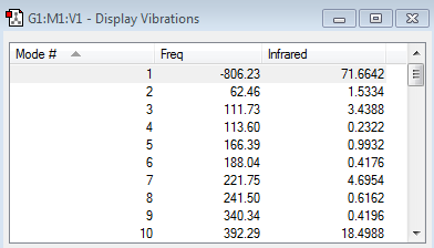
The endo transition state structure (log file) was located by first optimizing the structure of the final endo product at the AM1 Semi-Empirical level of theory (log file) and then changing the bond distances between the carbon atoms that form the two sigma bonds to 1.92 Å and the distance between the doubly bonded carbon atoms to 1.62 Å. The resulting structure was then optimized to a TS(Berny) by employing the AM1 Semi-Empirical level of theory. An analogous process was employed to determine the exo transition structure. The results obtained for the endo and exo transition structures are shown below. (log file for exo product) (log file for exo transition state structure)
| Transition Structure Conformation | Structure | Calculation Summary | Vibrational Calculations | ||
|---|---|---|---|---|---|
| Endo | 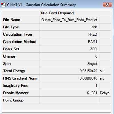
|
| |||
| Exo | 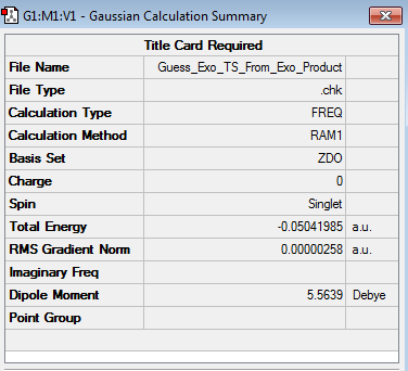
|

|
From the results above it followed that the computed endo and exo transition state structures were both transition structures, as they only featured a single imaginary frequency (occurring at -806.23 cm-1 and -812.20 cm-1 for the endo and exo TS respectively). Whilst the energy obtained for the endo transition state structure was found to be -0.05150479 a.u., the exo transition state structure featured an energy of -0.05041985 a.u., thus meaning that the endo transition state structure was lower in energy by 0.00108494 a.u. = 0.6808 kcal/mol.
The structural differences for the endo and exo transition state structures are illustrated below.
| Transition Structure Conformation | C1-C4 [Å] | C1-C2 [Å] | C2-C7 [Å] | C1-C22 [Å] | C16-C22 [Å] |
|---|---|---|---|---|---|
| Endo | 1.39730 | 1.39305 | 2.16242 | 2.89219 | |
| Exo | 1.39676 | 1.39437 | 2.17039 | 2.94499 |
The structural data for both the endo and the exo transition state structure illustrates that the bond distances between the C1-C2 and C2-C7 (hence also C3-C9) were very similar to each other (approx. 1.39 Å). This distance was longer than the bond length of a typical C=C bond (1.34 Å), but shorter than the bond length of a typical C-C bond (1.54 Å), hence meaning that the rupture of the C1-C2 and C3-C4 double bonds and the formation of the C1-C4 double bond had already progressed significantly in the TS. Additionally, the bond distance between the σ-bond forming atoms (C2-C7 and C3-C9) had already been reduced to approximately 2.17 Å in both the exo and endo transition state structure, thus being shorter than the sum of two carbon van der Waals radii (3.40 Å), hence being indicative of a strong primary orbital overlap between C2-C7 and C3-C9 in the TS.
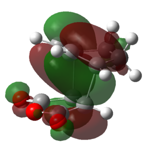
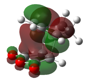
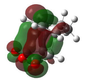
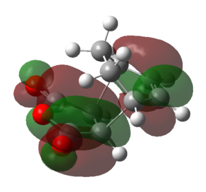
Despite these similarities between the exo and the endo TS, the exo TS featured a longer through space C-C distance (2.94499 Å) between the carbon atoms on the -(C=O)-O-(C=O)- fragment and the C atoms on the bridge opposite to it compared to the endo TS (2.89219 Å). Consequently, from a purely steric argument, the exo TS should have been lower in energy than the endo TS, due to its reduced steric hindrance. The increased stability of the endo TS over the exo TS thus must have had an orbital overlap origin. It was thus decided to construct a range of MOs for the endo and exo TS. Find the jmol structures of the orbitals represented below here [1]
(While the exo C16-C22 is indeed longer than the C1-C22 distance, you need to also consider the hydrogen atoms that are introduced to the exo structure at this point Tam10 (talk) 10:34, 1 February 2016 (UTC))
| HOMO-1 | HOMO | LUMO | LUMO+1 | LUMO+2 | |
|---|---|---|---|---|---|
| Endo | 
|
|

|
|
|
| Symmetry | Symmetric | Anti-symmetric | Anti-symmetric | Symmetric | Anti-symmetric |
| Exo | 
|

|
|

|

|
| Symmetry | Symmetric | Anti-symmetric | Anti-symmetric | Symmetric | Anti-symmetric |
From the above table it can be seen that the LUMO+1 and the LUMO+2 of the endo TS showed a stabilizing in-phase orbital overlap between the π-system of the C1-C4 double bond and the π* system of the C20-O and C22-O double bonds. This orbital overlap is referred to as a secondary orbital overlap and was responsible for the stabilization of the endo TS. On the other hand, the exo TS could not be stabilized by the secondary orbital overlap of the C1-C4 π-system and the π* system of the C20-O and C22-O due to the increased distance between the two systems. Consequently this explained why the endo TS was lower in energy than the exo TS, despite suffering from increased steric strain. Ultimately, this also meant that for the reaction of cyclohexa-1,3-diene with maleic anhydride the endo TS represents a lower energy reaction pathway, thus meaning that the endo product is the kinetic product and will be formed preferentially over the exo product.
To further confirm this hypothesis it was decided to calculate the activation energies of the reaction of cyclohexa-1,3-diene with maleic anhydride across the exo and endo transition structure. This was done by first optimizing the structure of cyclohexa-1,3-diene (log file) and maleic anhydride (log file) at the AM1 semi-empirical level of theory and then calculating the energy difference between these two structures and the endo and exo transition structure. The results are shown in the tables below.
Note: All displayed energy values are given in Hartrees
| Electronic Energy | Sum of electronic and zero-point energies at 0 K | Sum of electronic and thermal energies at 298.15 K | |
|---|---|---|---|
| Cyclohexa-1,3-diene | 0.027711 | 0.152500 | 0.157724 |
| Maleic Anhydride | -0.121824 | -0.063349 | -0.058198 |
| Endo TS | -0.051505 | 0.113494 | 0.143683 |
| Exo TS | -0.0504020 | 0.134881 | 0.144882 |
Note: All displayed energy values are given in kcal/mol
| AM1 Semi-empirical at at 0 K | AM1 Semi-empirical at 298.15 K | |
|---|---|---|
| Eact(Endo) | 15.28 | 27.71 |
| Eact(Exo) | 27.70 | 28.46 |
(I can see why you have a low number for the endo activation energy at 0K: you've put down 0.113494 a.u. instead of the 0.133494 a.u. that's in the log file Tam10 (talk) 10:34, 1 February 2016 (UTC))
From the above table it followed that the activation energy for the reaction between cyclohexa-1,3-diene and maleic anhydride was lower for the endo transition structure than the exo transition at both 0 K and 298.15 K. Whilst at 0 K there was a significant difference in energy between the activation energies across the endo or exo transition structure (12.42 kcal/mol), the difference in energy between the activation energies across the endo or exo transition structure became significantly smaller as the temperature was increased to 298.15 K (0.75 kcal/mol). This clearly illustrated that the product distribution for the Diels-Alder reaction between cyclohexa-1,3-diene and maleic anhydride was also temperature dependent.
Conclusion
In conclusion this computational study focused on three different reactions: the Cope rearragnement of 1,5-hexadiene, the Diels Alder cycloaddition of butadiene with ethene and the Diels Alder cycloaddition of cyclohexa-1,3-diene with maleic anhydride. The aims for each of these reactions included to:
- determine the structure and the energy of the reactants
- determine the structure and the energy of the various transition state structures
- determine the preferred reaction pathway by calculating the activation energies across the various transition states
The calculations performed where carried out at three different levels of theory, namely at the HF/3-21G, the B3LYP/6-31G* and the AM1 Semi-empirical level of theory.
The results obtained for the Cope-rearrangement of 1,5-hexadiene demonstrated that there are two possible reaction pathways, one across a chair and one across a boat transition state structure. It was found that the reaction across the chair TS conformation was energetically more favorable, as the boat TS was destabilized by the eclipsed conformations along C1-C6 & C3-C4 and the steric interactions of flagpole hydrogens.
The outcomes of the Diels-Alder cycloaddition of cyclohexa-1,3-diene and maleic anhydride instead illustrated that the pericyclic reaction can proceed through either an endo or exo transition state, with the endo transition structure being lower in energy due to stabilizing secondary orbital interactions.
The main source of error within the calculations performed lies within the fact that no intermolecular forces have been considered, which of course could have a dramatic impact on the calculations' output.
References
- ↑ Fouch, R.; Gung, B.J.; Zhu, Z. J. Am. Chem. Soc. 1995, 117, 1783-1788
- ↑ von Doering, W.E.; Toscano, V.G.; Beasley, G.H. Tetrahedron, 1971, 99, 5299
- ↑ Hornback, J.M. Organic Chemistry, Thomson Learning, Boston (MA), 2nd edn., 2006, ch.6, 178-218
- ↑ Gilchrist, T.L.; Storr, R.C. Organic Reactions and Orbital Symmetry, Cambridge University Press, Cambridge, 2nd edn., 1979, ch. 2, 21-43
- ↑ Tia, R.; Asempa, E; Adei, E. J. Theor. Comput. Sci.,2014, 3, 1-12
- ↑ Manku, G.S. Theoretical Principles of Inorganic Chemistry, Tata McGraw-Hill, New Delhi, 1st edn., 1980, ch.3, 77-123
- ↑ Bach, R.D.; McDouall, J.J.; Schlegel, H.B. J. Org. Chem., 1989,54, 2931-2935

