Mod123CLMAFC
3rd Year Computational Labs
Module 1 - Structure and Spectroscopy
Part 1.2.1 - The Hydrogenation of Cyclopentadiene Dimer


Using ChemBio 3D the geometry of the cyclopentadiene dimer is defined and optimised using the MM2 force field. A calculation of the total energy of the dimers 1 and 2 (see figure 1) gives 133.43 kJ/mol and 142.30 kJ/mol respectively. This indicates that product 1 is the thermodynamic product and product 2 is the kinetic product. Product 2 the endo-product is produced exclusively, this is due to the reaction mechanism by which the product is formed. The dimerisation of cyclopentadiene occurs via Diels Alder a cycloaddition, using the frontier orbital approach it is clear why it is that the endo product is formed. Figure 2 shows a simplified picture of the HOMO of the diene and the LUMO of the dienophile, the dashed lines indicate where the new carbon-carbon bonds form. From the diagram the secondary orbital effect becomes apparent, causing the cyclopentadiene ring acting as the dienophile to "fold underneath" the diene producing the endo-product.
The possible geometry of the hydrogenation product is defined in figure 1, products 3 and 4, optimisation yields total energies of 154.22 kJ/mol and 122.38 kJ/mol respectively. This would indicate that the thermodynamic product is product 4 as it has a lower total energy. The stretching, bending, and Van der Waals terms show that structure 3 has higher deviation from normality indicating that the bonds are stretched and bent further from the ideal, this adds to the total energy of the molecule. As can be seen the torsion in 4 is higher than in 3, however all of the other contributions in 3 outweigh this factor.
| Property | Product 3 | Product 4 |
|---|---|---|
| Stretch | 1.24 | 1.13 |
| Bend | 18.72 | 13.07 |
| Torsion | 12.79 | 14.23 |
| Van der Waals | 6.05 | 4.44 |
Part 1.2.2 Stereochemistry of Nucleophilic addidtions to a pyridinium ring (NAD+ analogue)


The reactant 5 in figure 3 was defined using ChemBio 3D and the structure optimised using the MM2 field. The resulting molecule showed a dihedral angle between the carbonyl group and the planar ring of 11o. Examining the product of the reaction of 5 with a Grignard reagent MeMgI shows a stereo-selective addition to the pyridinium ring, where the nucleophile Me- attacks the top face. As the carbonyl is not in the same plane as the pyridinium ring it suggests that the oxygen lone pairs must stabilise the reaction intermediate by coordinating to the magnesium cationic centre.
Reactant 7 see figure 4 was defined using ChemBio 3D and again the structure was optimised using the MM2 field. As in 5 the carbonyl group does not lie in the plane of the quinolinium ring and shows a dihedral angle of -20o. Examining the product 8 in figure 4 shows a stereo-selective electrophilic addition of a phenyl amine to the quinolinium ring. This is a result of the interaction of the nitrogen lone pair of the incoming electrophile and the oxygen lone pairs on the carbonyl, repulsion between electron densities discourages attack on the bottom face of the molecule explaining the stereochemistry of the product.
Part 1.2.3 Stereochemistry and Reactivity of an Intermediate in the Synthesis of Taxol

Using the MM2 field to optimize structures 9 and 10 (see figure 5) energies of 246.21 kJ/mol and 182.52 kJ/mol respectively are presented with a difference of 63.70 kJ/mol. A second optimisation using the MMFF94 Minimization gave a difference in energy of 91.24 kJ/mol with structure 10 being again lower in energy. Therefore the most stable structure is intermediate 10. Both isomers are hyperstable alkenes but it can be seen in structure 10 the carbonyl is on the opposite face to the bridging, this increases stability due to a reduction in steric clashing. Structure 10 also appears to be a hyperstable alkene. This is demonstrated by the position of the double next to a bridge head and the large difference in energies.
Part 1.3.1 Regioselective Addition of Dichlorocarbene
After optimising the geometry of compound 11 (figure 6) using MOPAC/PM6 an approximate representation of the valence-electron molecular wavefunction can be seen. It is clear from examining the HOMO-1, HOMO, LUMO, LUMO+1 and LUMO+2 representations that there is a clear difference between the two alkene bonds on the molecule. Examining the HOMO more closely leads to the conclusion that the alkene bond syn to the chlorine is the most nucleophilic as it shows a greater surface area which is available for electrophilic attack.


Using the optimised structures of 11 and 12 (figure 6) the vibrational modes of both molecules were analysed.
| Bond | Stretching Frequency cm-1 (Compound 11) | Stretching Frequency cm-1 (Compound 12) |
|---|---|---|
| Syn C=C | 1757.32 | 1753.76 |
| Anti C~C | 1736.99 | 1094.24 |
| C-Cl | 770.925 | 779.924 |
From the data it can be seen that the upon hydrogenation of the anti-alkene the strength of the syn-alkene bond is reduced, this is demonstrated by less energy being required to vibrate the bond. This indicates that electron density must be withdrawn from the syn-alkene bond. This being the case it is likely that the electronegative chlorine polarises the alkene π bond, thus reducing the bond strength.
Part 2. Structure based Mini project using DFT-based Molecular orbital methods


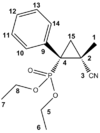
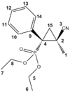
The electrosynthesis of α-arylated β-substituted cyclopropylphosphonates, yields two isomers, a cis isomer with respect to the phosphate (figure 12) and a trans isomer with respect to the phosphate (figure 13). This racemisation is a result of the reaction to form the cyclopropyl ring. The reaction schematic can be seen in figure 14. The lack of stereo specificity leads to the conclusion that the reaction proceeds via a stepwise addition of a triplet carbene. This allows for bond rotation and consequently isomers (see figure 15).


After optimising both structures using Gaussian the NMR shift for both structures was calculated. (Data for the cis and trans isomers can be found at http://hdl.handle.net/10042/to-5687 and http://hdl.handle.net/10042/to-5686 respectively).
| Carbon | Lit Cis Shift/ ppm | Calc Cis Shift/ ppm | Lit Trans Shift/ ppm | Calc Trans Shift/ ppm |
|---|---|---|---|---|
| 1 | 20.2 | 22.4 | 17.9 | 19.6 |
| 2 | 14.6 | 19.3 | 18.5 | 21.6 |
| 3 | 121.3 | 118.0 | 121.0 | 117.0 |
| 4 | 34.3 | 40.7 | 33.5 | 40.9 |
| 5 | 63.5 & 63.0 | 62.7 | 62.8 & 63.0 | 62.3 |
| 6 | 16.4 | 18.9 | 16.4 | 19.2 |
| 7 | 16.4 | 18.0 | 16.4 | 17.4 |
| 8 | 63.5 & 63.0 | 62.2 | 62.8 & 63.0 | 58.7 |
| 9 | 135.4 | 130.0 | 135.4 | 132.1 |
| 10 | 128.5 | 128.7 | 128.5 | 128.0 |
| 11 | 128.7 | 126.0 | 128.7 | 125.5 |
| 12 | 132.8 | 125.6 | 132.8 | 125.6 |
| 13 | 128.7 | 124.7 | 128.7 | 125.1 |
| 14 | 128.5 | 128.7 | 128.5 | 129.0 |
| 15 | 24.4 | 27.4 | 24.7 | 27.4 |
From the table it is clear that most of the calculated shifts are with in 0-5ppm of those cited in the literature. This indicates that the assignment of the cis and trans isomers is correct. For further proof of the correct assignment Janocchio was employed to determine the coupling coupling constant between the phosphorus and C3 in both the cis and trans cases, unfortunately this was unsuccessful with all attempts to obtain a coupling constant resulting in a zero reading.
References
- A. G. Shultz, L. Flood and J. P. Springer, J. Org. Chemistry, 1986, 51, 838. DOI:10.1021/jo00356a016
- S. Leleu, C.; Papamicael, F. Marsais, G. Dupas, V.; Levacher, Vincent. Tetrahedron: Asymmetry, 2004, 15, 3919-3928. DOI:10.1016/j.tetasy.2004.11.004
- B. Halton, R. Boese and H. S. Rzepa., J. Chem. Soc., Perkin Trans 2, 1992, 447. DOI:10.1039/P29920000447
- S. W. Elmore and L. Paquette, Tetrahedron Letters, 1991, 319; DOI:10.1016/S0040-4039(00)92617-0 10.1016/S0040-4039(00)92617-0 10.1016/S0040-4039(00)92617-0
- A. B. McEwen, P. v. R Schleyer, J. Am. Chem. Soc, 1986, 108 (14). Template:DOI: 10.1021/ja00274a016
