Ccomplab2-01385364
Chemistry Computational Lab 2 - Modelling
NH3
NH3 Optimised |
File:BGAGGIO NH3 OPT POP FIRSTEX.LOG
Optimization
Calculation Method = RB3LYP
Basis Set = 6-31G(d,p)
E(RB3LYP) = -56.5577687299 a.u.
Dipole moment = 1.5008 Debye
Point Group = C3V
Geometry
Angle = 105.741 degrees
Bond Length = 101.798 pm
Opt File
Item               Value     Threshold  Converged?
 Maximum Force            0.000004     0.000450     YES
 RMS     Force            0.000004     0.000300     YES
 Maximum Displacement     0.000072     0.001800     YES
 RMS     Displacement     0.000035     0.001200     YES
Vibrational Frequencies
How many modes do you expect from the 3N-6 rule? 6
Which modes are degenerate (ie have the same energy)? Mode 2-3 and mode 5-6
Which modes are "bending" vibrations and which are "bond stretch" vibrations?
Bending = 1, 2, 3
Stretching = 4, 5, 6
Which mode is highly symmetric? 4
One mode is known as the "umbrella" mode, which one is this? 1
How many bands would you expect to see in an experimental spectrum of gaseous ammonia? 4: there are two sets of degenerate values which would give the same value.
Charges: N = 1.125 H = 0.375
N2
N2 Optimised |
Optimization
Calculation Method = RB3LYP
Basis Set = 6-31G(d,p)
E(RB3LYP) = -109.524128676 a.u.
Opt File
Item               Value     Threshold  Converged?
 Maximum Force            0.000001     0.000450     YES
 RMS     Force            0.000001     0.000300     YES
 Maximum Displacement     0.000000     0.001800     YES
 RMS     Displacement     0.000000     0.001200     YES
 Predicted change in Energy=-3.401116D-13
Vibrational Frequencies
H2
H2 Optimised |
Optimization
Calculation Method = RB3LYP
Basis Set = 6-31G(d,p)
E(RB3LYP) = -1.17853936 a.u.
Opt File
         Item               Value     Threshold  Converged?
 Maximum Force            0.000000     0.000450     YES
 RMS     Force            0.000000     0.000300     YES
 Maximum Displacement     0.000000     0.001800     YES
 RMS     Displacement     0.000001     0.001200     YES
 Predicted change in Energy=-1.164080D-13
Vibrational Frequencies
Haber-Bosch Reaction Energy Calculations
E(NH3)= -56.5577687299 a.u.
2*E(NH3)= -113.1155374598 a.u.
E(N2)= -109.524128676 a.u.
E(H2)= -1.17853935735 a.u.
3*E(H2)= -3.53561807205 a.u.
ΔE=2*E(NH3)-[E(N2)+3*E(H2)]= -112.88794376+113.05974674805 = -0.05579071175 a.u. = 146.478513699625 kJ/mol
ΔE = 73.239 kJ/mol = energy to turn the gaseous components (N2 and H2) into ammonia (NH3)
Ammonia is deeper in energy than H2, hence it is more stable than it. However, N2 is deeper in energy than ammonia, which makes ammonia least stable than this gaseous component.
F2
F2 Optimised |
Bond length = 1.40281
Optimization
Calculation Method = RB3LYP
Basis Set = 6-31G(d,p)
E(RB3LYP) = -1.17853936 a.u.
Opt File
         Item               Value     Threshold  Converged?
 Maximum Force            0.000128     0.000450     YES
 RMS     Force            0.000128     0.000300     YES
 Maximum Displacement     0.000156     0.001800     YES
 RMS     Displacement     0.000221     0.001200     YES
 Predicted change in Energy=-1.995024D-08
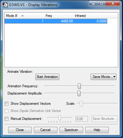
Vibrations: Only one vibration = stretch = 1065.09
Molecular Orbitals
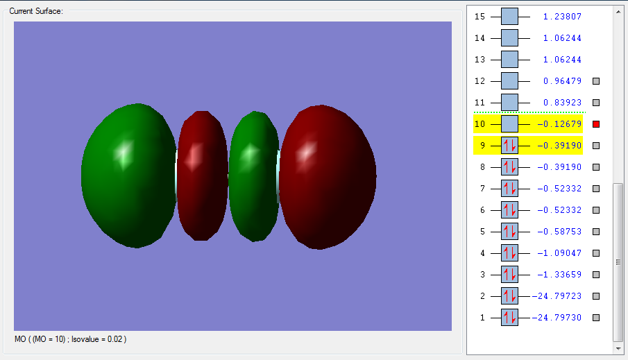
The molecular orbital diagram for the F2 molecule involves the overlap of the 1s orbitals (2 electrons each), the 2s orbitals (2 electrons each) and the 2p orbitals (5 electrons each, unfilled). The bond order of the molecule is 1.
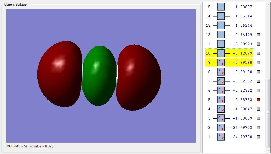
Figure 1 is the highest LUMO for F2, an unoccupied anti bonding orbital high in energy. This is the sigma*u orbital made from the out of phase overlap of the 2pz half filled atomic orbitals in fluorine. The parity label indicates that after an inversion on the centre of the orbital, the negative and positive signs are swapped. This MO will decrease the bonding since it is anti bonding. The corresponding bonding and occupied sigma orbital is pictured in Figure 2. Here the overlap is in-phase, with constructive contributions from the 2pz atomic orbitals in fluorine. This bonding orbital is lower in energy and more stable. It contributes to bonding and it has a parity label g. In-phase and out of phase overlap tells us about the symmetry of how the AOs are overlapping. In-phase is positive, constructive overlap, resulting in a bonding orbital (which contributes to bonding), whereas out-of-phase is negative and destructive, resulting in an anti bonding orbital.
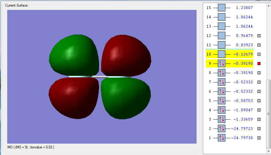
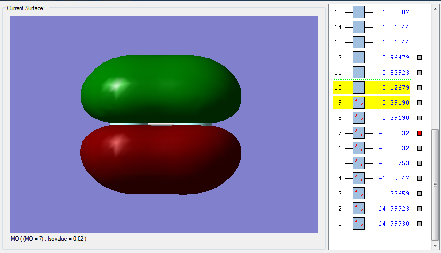
The overlapping of the other two 2p orbitals, 2px and 2py, leads to pi orbitals. Figure 3 shows the pi*g orbital: this is the occupied anti bonding orbital, resulting from the out of phase and destructive side ways over lap of the 2p orbitals just mentioned. Pi*x and pi*y are degenerate. The shape of the molecular orbital is shown in Figure 3 and is equal for both. This can also be seen from the energies, which are equal, for MO 9 and MO 8. Similarly, the constructive and in-phase overlap of the x and y 2p orbitals leads to two degenerate pi orbitals, as shown in Figure 4. Again, the energies are equal, degenerate: MO 7 = MO6, which are pix and piy. The only difference between these orbitals are the axis plane in which they lay. Figure 4 represents the HOMO, highest energy occupied MO.
The difference between sigma and pi orbitals can be explained with Figures 1 to 4. Sigma orbitals don’t change sign when rotated 180 degrees around the internuclear axis. This is in fact true for Figure 1 and 2, but not for Figure 3 and 4. In these last two MOs, rotation around the internuclear axis by 180 degrees reverses the sign, which is the definition of a pi MO.
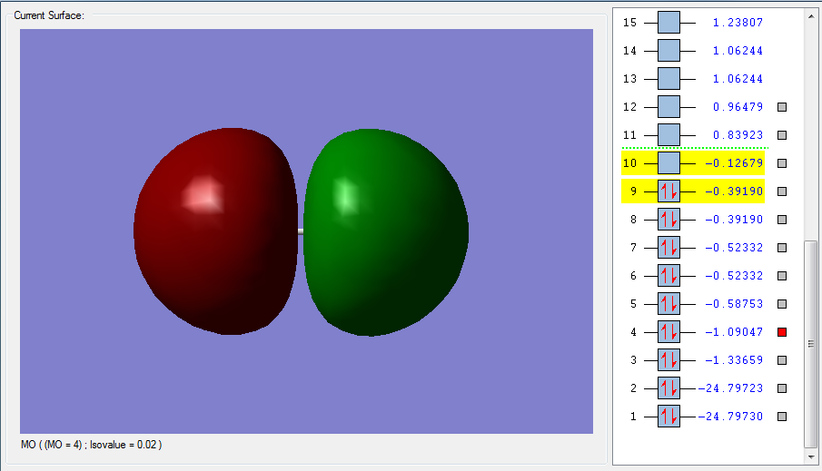
Finally, Figure 5 represents the MO from the mixing of the AOs from the 2s orbital. Figure 5 is the sigma* MO that arises from the deconstructive and out of phase overlap of two 2s orbitals. The corresponding sigma MO (which forms from the same two AOs) is not shown, however it would simply be a spherical, slightly oval, shape around the two nuclei. What is interesting about the sigma* MO is the presence of a node that cuts it in half. Nodes are areas of zero electron density, or where the probability of finding one is zero. Nodes increase the energy of an MO. In fact, the sigma* is higher in energy than the sigma, which makes it less unstable. The number of nodes is proportional to the energy, in fact Figure 1, the MO with highest energy reported here, has three nodes.


